Abstract
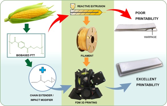
This work features the first-time use of poly(trimethylene terephthalate) (PTT), a biobased engineering thermoplastic, for fused deposition modeling (FDM) applications. Additives such as chain extenders (CEs) and impact modifiers are traditionally used to improve the processability of polymers for injection molding; as a proof of concept for their use in FDM, the same strategies were applied to PTT to improve its printability. The filament processing conditions and printing parameters were optimized to generate complete, warpage-free samples. The blends were characterized through physical, thermal, viscoelastic, and morphological analyses. In the optimal blend (90 wt % PTT, 10 wt % impact modifier, and 0.5 phr CE), the filament diameter was improved by ∼150%, the size of the spherulites significantly decreased to 5% of the ∼26 μm spherulite size found in neat PTT, and the melt flow index decreased to ∼4.7 g/10 min. From this blend, FDM samples with a high impact performance of ∼61 J/m were obtained, which are comparable to other conventional FDM thermoplastics. The ability to print complete and warpage-free samples from this blend suggests a new filament feedstock material for industrial and home-use FDM applications. This paper discusses methods to improve hard-to-print polymers and presents the improved printability of PTT as proof of these methods’ effectiveness.
1. Introduction
Three-dimensional (3D) printing is an additive manufacturing (AM) process with the benefit of high customization and cost effectiveness for complex parts or prototypes.1 Fused deposition modeling (FDM) or fused filament fabrication is a 3D printing method that extrudes a thermoplastic filament through a heated nozzle to build a physical part based on a computer-aided design (CAD) model. This technology is increasing in popularity and is used for both rapid prototyping and component manufacturing,1 where it has been used in biomedical and industrial applications.2
One of the most common polymers used in FDM is poly(lactic acid) (PLA),3 which is both a biobased and biodegradable polymer. Recently, researchers have combined PLA with natural fillers, such as microcrystalline cellulose, to diversify its mechanical performance4 while maintaining its renewability. Other works have combined petroleum-based polymers with natural fillers or fibers, such as lignin,5 biochar,6 and biogenic carbon,7 to improve renewability and mechanical performances. Recycling polymers, such as poly(ethylene terephthalate) (PET), for improved sustainability have also been of interest to generate new filament feedstocks.6 Other recycled polymers include poly(ethylene-2,5-furandicarboxylate), which is derived from biomass and recycled and reused successfully for FDM.8 The use of these polymers and composites alleviates some of the environmental concerns with regard to waste and renewability, as well as addresses the use of sustainable polymers for FDM.9
Other commonly used materials for FDM are engineering thermoplastics, such as polyamides (PAs) and polycarbonates (PCs),10 that offer some benefits over traditional thermoplastics. One of the most commonly used engineering thermoplastics in AM is acrylonitrile butadiene styrene (ABS)3 because of its superior thermal stability and mechanical properties. However, ABS is nonbiodegradable and petroleum-sourced. The added benefits of engineering thermoplastics and sustainable polymers create the demand for more variability in FDM feedstocks. Focus has begun to shift to the development and modification of other engineering thermoplastics and sustainable polymers for FDM technologies.9,11
Engineering thermoplastics from renewable sources have the potential to generate products with exceptional mechanical performance and improved thermal stability, while addressing environmental concerns. Poly(trimethylene terephthalate) (PTT) is a partially biobased engineering thermoplastic which displays mechanical properties similar to nylon and chemical properties similar to PET.12 However, the semicrystalline nature of this polymer can cause challenges during 3D printing. Semicrystalline polymers are less commonly used in FDM because of shrinkage and warpage caused by formation of crystalline regions during cooling of deposited layers.13 Engineering thermoplastic polyesters, such as PTT, PET, and poly(butylene terephthalate) (PBT), are often difficult to be 3D printed because of their high melting temperatures, crystallinity, and hydrophilic nature.14 Printing polyesters can be improved with the addition of additives. For example, PBT and carbon nanotubes/graphene have been printed to generate mechanically robust and highly functional products.15 Likewise, additives present in recycled PET led to improved printability, as compared to neat PET, to create complete, warpage-free samples.14 Printing of these polymers can be improved with the help of additives such as nucleation inhibitors, chain extenders (CEs), and reactive compatibilizers or by blending with other polymers.
An impact modifier contains reactive epoxy groups which react with the hydroxyl and carboxyl groups16 of polymer chains to improve performance. Studies have analyzed the interaction of impact modifiers with polyesters17 to improve their toughness18 and increase the melt strength of these polymers. The addition of an impact modifier may increase the dimensional stability of the filaments for FDM applications. Further improvements to FDM-printed materials were predicted to occur with the addition of a CE. A CE can be added to polymers to prevent polymer degradation and help increase their thermal stability. This may aid in filament printing by increasing the polymer’s melt viscosity. Rasselet et al.19 used a CE with PLA/nylon 11 blends to compatibilize the materials and improve the printability. Zander et al.14 proposed the use of CEs to improve the printability of FDM-recycled PET. Therefore, it is likely that these materials can be added to polymers to successfully optimize for FDM.
The success of FDM is highly dependent on the printing parameters used, including bed temperature, nozzle temperature, print speed, and layer height, which can all have effects on the properties and printability of a FDM-printed part.20−22 The parameters can be optimized for product finish, tailored mechanical performances, cost savings through material reduction, and product efficiency through management of speed and quality. Torres et al.20 studied the impact of relative density, thickness, print temperature, infill direction, print speed, and orientation on the mechanical performance of PLA. On the basis of optimization of printing parameters, they concluded that a part with good tensile and fracture properties required a layer thickness of 0.3 mm, a raster angle/infill density of 45°/135°, and a perimeter added to each part.20 Benwood et al.21 studied the effect of melt temperature, bed temperature, and raster angle of PLA to improve impact strength and heat resistance. With optimal print orientation raster angles of 45° and 135°, the authors determined that the mechanical performance can be changed by variation of temperature parameters and that the bed temperature had a large effect on the thermal analysis of the samples because of the changes in crystallinity. Anitha et al.22 optimized printing parameters for desirable surface finishes. They performed a Taguchi design of experiments to determine the effect of print speed, layer thickness, and road width with ABS. The authors determined that surface finish is most affected by the layer thickness. Printing parameters must be investigated to optimize the properties of FDM materials.
Because there is a constant desire in AM to generate new polymer blends or composites with a larger variety of mechanical performances,23 this work addresses the concerns of limited filament feedstocks commercially available.24 A larger number of FDM materials can be adapted to function for more applications in industry and home printing.25 Three fundamental aspects for 3D printing are discussed in this work: (1) methods commonly implemented to improve injection molding practices can be applied to FDM to reduce warpage and improve processability or printability; (2) the combination of additives (impact modifier and CE) with neat polymers can theoretically improve the printability of other challenging highly crystalline polymers; and (3) unique blends of additives and PTT can lead to a larger variety of filament feedstocks to foster the use of FDM in a larger variety of applications. This paper features the novel use of biobased PTT as a 3D printing material for FDM. To the best of authors’ knowledge, no other work has been completed with PTT as a FDM feedstock. Although there are many studies on the effect of printing parameters, investigation into the effect of additives such as CEs and impact modifiers on printability is limited.
2. Results and Discussion
This work was completed in two parts. The first part features strand optimization to increase printability, followed by printing optimization and characterization of the blend’s properties. The nomenclature and composition for the blends can be found in Table 1.
Table 1. Nomenclature and Composition of PTT Blends.
| Name | PTT content (wt %) | EBA-GMA content (wt %) | SA-GMA content (phr) |
|---|---|---|---|
| Neat PTT | 100 | ||
| 100/0/0.25 | 100 | 0.25 | |
| 100/0/0.5 | 100 | 0.5 | |
| 95/5/0.5 | 95 | 5 | 0.5 |
| 90/10/0 | 90 | 10 | |
| 90/10/0.25 | 90 | 10 | 0.25 |
| 90/10/0.5 | 90 | 10 | 0.5 |
| 85/15/0.5 | 85 | 15 | 0.5 |
2.1. Stand Optimization
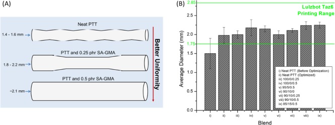
It is essential in FDM that filaments are dimensionally suited to the specific printer’s parameters. Consistency in filament diameter is also imperative to ensure proper feeding through the nozzle. The printer used in this study, a Lulzbot Taz 6 printer, has a minimum filament diameter recommendation of 1.75 mm. Neat PTT filaments processed on the Leistritz at 250 °C and 100 rpm (in accordance with the literature29), with a feed rate of 5 kg/h and a collector speed of 600 rpm, had filament diameters of approximately 1.4–1.6 mm with poor consistency. As can be seen in Figure 1, the filaments generated were very thin, had poor consistency when printing, and showed a tendency to jam the nozzle, which resulted in difficulties to print a completed part. Thin filaments often result in slippage and buckling of the filament in the feeding system, or underfilling of the rasters which leads to poor inter-raster cohesion.30 Various strategies were attempted to optimize the extruded filament. Processing conditions were modified, and additives were introduced to create printable strands. The success of these techniques to optimize PTT filaments indicates that they could be applied to develop a variety of polymers for FDM.
Figure 1.
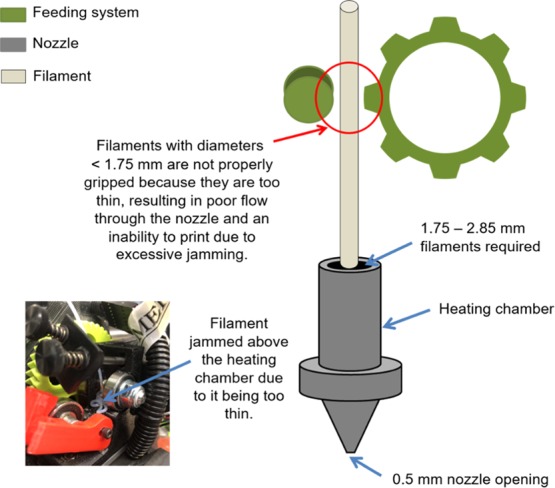
Schematic of the challenges posed by thin filaments in FDM.
Screw speed was investigated as it was anticipated that a reduced screw speed would decrease the shear rate on the melted polymer, thereby increasing its viscosity31 and the resultant strand diameter. However, this was found to have a negligible effect with all filament diameters measured at ∼1.7 mm, thereby suggesting that further optimization was needed. Therefore, the original 100 rpm speed was maintained to match the literature values.17,18 The effect of barrel temperature was also investigated. With reduced temperature, PTT becomes more viscous.28,29 Therefore, at lower melt temperatures, the material should be pushed out of the die in thicker strands. This was observed in the PTT strands with the diameter increasing by 116% from 1.42 mm for 250 °C processed filaments. 240 °C was chosen as the optimal barrel temperature to maintain thicker strands. To further improve the filament diameter, factors such as feed rate and collector speed were investigated. A consistent feed rate can lead to a constant weight and composition.32 Feed rate is the rate of material fed into the hopper. By varying the feed rate between 5 and 8 kg/h, 7 kg/h was determined to be the optimal rate, which was verified by producing strands with the greatest diameter without overloading the screw. The 7 kg/h feed rate produced samples with a filament diameter of 1.98 mm on average, which was 113% greater than the 5 kg/h samples. The 8 kg/h samples produced even larger diameters, but there was high shear on the screws. Because the 7 kg/h filament diameter was within the printing range, it was chosen as the ideal feed rate. As noted by Chung,32 the feed rate contributes to beneficial conditions, such as improved bulk density, a higher melting point, a small surface area-to-volume ratio, and reduced friction from the hopper surface. Collector speed is the speed at which the wheel that draws the material through the water bath spins. This speed needs to be chosen to ensure that the filaments are pulled fast enough through the water bath to avoid kinking and build ups of material but slow enough to maintain diameters larger than 1.75 mm. The resulting optimized speed was 465 rpm. The lower collection speed increases the cooling time of the filament, which allows the filament to maintain dimensional stability by cooling it to a complete internal temperature below the glass-transition temperature.33 Therefore, the slower collection rate improved the filament thickness.
With a melt temperature of 240 °C, a screw speed of 100 rpm, a feed rate of 7 kg/h, and a collection rate of 465 rpm, the strands had a thick enough diameter to print, but the print quality was poor. Samples that did print were very warped and the nozzle continued to jam because of uneven diameters throughout the strand. The effects of additives were investigated to determine their impact on filament size, consistency, and printability.
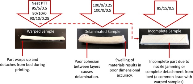
The effect of a CE (SA-GMA) on the printability of PTT was investigated because CEs can increase the melt stability of the polymer.26 PTT was unable to print at a temperature of 250 °C in the Lulzbot printer. Therefore, higher temperature was required to extrude the filament for printing. After several optimization printing processes, we found that the PTT filament was able to extrude and flow properly at 290 °C. In order to avoid severe degradation of PTT when printing at high temperature, a small amount (0.25–0.50 phr) of CE (SA-GMA) was added. We found that the SA-GMA CE could improve the dimensional stability and consistency of the PTT filament during processing. The addition of 0.5 phr SA-GMA resulted in an average strand diameter, ∼140% the size of the neat PTT strand, as can be seen in Figure 2b. A visual schematic of the changes in filament diameter is displayed in Figure 2. The CE contains numerous functional groups, which can interact with the broken PTT chains,34 thereby increasing the branching of the polymer, which leads to an increase in molecular weight and overall improved thermal stability.35 The addition of SA-GMA made the filaments to be within the allowable size for the printer; however, the printed parts displayed delamination and had poor dimensional accuracy because of the material’s tendency to expand and swell after printing, which is discussed in later sections (Figure 6).
Figure 2.
(a) Schematic of the effect of addition of a CE on filament diameter and (b) average filament diameter of blends (ii–ix show the results after processing conditions were optimized).
Figure 6.
Schematic of issues with FDM of neat PTT and blends.
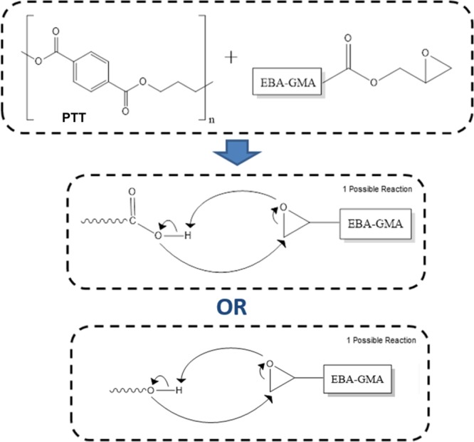
The effect of EBA-GMA as an impact modifier and thermal stabilizer was also studied. EBA-GMA had minimal effect on filament diameter but increased its consistency; therefore, the optimal content was 10 wt %. EBA-GMA was anticipated to have pronounced interactions with the carboxyl and hydroxyl groups of PTT18 as seen in the proposed reactions shown in Scheme 1.18 The addition of only EBA-GMA did not show any impact on printability as the filaments still tended to buckle above the heating chamber and printed parts still experienced warpage.
Scheme 1. Two Possible Reactions between EBA-GMA and PTT Adapted and Redrawn from Chang et al.18.
A combination of EBA-GMA and SA-GMA was tested (0–15 wt % EBA-GMA and 0–0.5 phr SA-GMA). These blends showed good consistency in filament diameter and had diameters above the required 1.75 mm diameter. In order to produce high toughness PTT, 10 wt % EBA-GMA was chosen as the optimal EBA-GMA content. The printable blends possessed some of the highest viscosities, as compared to the neat polymer. Hwang et al. explained that highly viscous materials act as an incompressible Newtonian fluid during processing, which results in a consistent cross section and increased diameter.36
The combination of SA-GMA and EBA-GMA was essential for the success of processing filaments and printing blends. On the basis of works from You et al.,17 the number of epoxy equivalent groups on SA-GMA is ∼24. This is derived from the number of epoxy group equal to the molecular weight of SA-GMA divided by the equivalent weight of epoxy (6800 g mol–1/285 g mol–1). On the basis of the assumption that SA-GMA contains nearly 10 times the content of glycidyl methacrylate,17 the EBA-GMA would potentially contain ∼2 reactive epoxy groups. Therefore, a combination of SA-GMA was needed to branch the polymer and EBA-GMA to increase the length of the polymer chains to improve the dimensional stability of the samples.
When optimizing filaments for printing, processing conditions should be investigated to ensure that optimal strands are produced. Filament diameters were increased from ∼1.4 to ∼2.0 mm just by optimizing the processing conditions of screw speed, barrel/melt temperature, feed rate, and collector speed. To further improve the printability of a polymer, the effect of additives should be investigated. The CE and impact modifier improved filament consistency and resulted in a printable, warpage-free blend (as discussed in the later section).
2.2. PTT-Based Blends and Their Characterization
The blends of PTT, EBA-GMA, and SA-GMA were characterized to investigate the impact of the additives on PTT’s properties and printability.
2.2.1. Physical Properties of Filaments
The filament diameter, melt flow index (MFI), and density were measured for neat PTT and its blends and are displayed in Table S1. The average diameter of neat PTT increased significantly to ∼2 mm because of the optimization of processing conditions from its original ∼1.4 mm diameter. The average diameter continued to increase with the increase of SA-GMA and EBA-GMA content. This was likely as a result of the bonding between polymer and additives, which acted to stabilize the melt flow and increase the filament size. MFI is a measure of a material’s flowability and is linked to a material’s viscosity. MFI drastically decreased with the addition of EBA-GMA, which is attributed to EBA-GMA’s tendency to increase the melt viscosity. SA-GMA also decreased MFI, which can be attributed to decreased chain mobility from increased cross-linking. The use of both an impact modifier and a CE increased the reactivity of the blends as noted by the reduced MFI. The density of the blends decreased with increasing EBA-GMA content because of the replacement of PTT with a lower density component (i.e., EBA-GMA with a density of 0.94 g/cm3).37
Filaments with less than 0.5 phr of SA-GMA still exhibited issues with warpage and buckling of the filament. This was due to their more inconsistent diameters, as they exhibited bumpier filaments, as displayed in Figure 2. Approximately 5.0 g/10 min appeared to be the minimum acceptable MFI value, as the 85/15/0.5 blend with a MFI less than 3.0 g/10 min experienced issues with underextrusion and poor flow during printing. The neat PTT had the opposite issue and experienced overflow not controlled by the feed system during printing, suggesting very high flowability. For successful extrusion, the filament needs to act as the piston pushing the material through the heating chamber.30 Nonideal flow behavior can result in a filament that is unable to successfully push the filament through, causing unregulated flow and jamming.30
2.2.2. Mechanical Properties of Injection-Molded Samples
The mechanical properties of the injection-molded samples for the blends were studied and are displayed in Table S2. The tensile and flexural strength as well as the modulus decreased with increasing EBA-GMA content in the PTT blend. This trend is typical of EBA-GMA blends, which was seen in the work by Yuryev et al.38 in PLA/PC blends.
The notched impact strength of the neat polymer and its blends can be seen in Figure 3. The notched impact strength of the samples increased to ∼240% in the 90/10/0.5 blends, as compared to the neat PTT. The sharp increase in notched impact strength value seen from 5 to 10 wt % EBA-GMA blends (from ∼50 to 98 J/m) can be classified as the brittle–ductile transition, which is typically seen with elastomer impact modifiers.38 No significant improvement was observed with further increase in EBA-GMA content to 15 wt % (i.e., 85/15/0.5 blend). This suggested that 10 wt % EBA-GMA could be sufficient for optimal results to achieve a desirable impact strength in PTT. Therefore, 10 wt % EBA-GMA was chosen for the ideal formulation. The 90/10/0.5 blend had good toughness properties and is very desirable because of its drastically improved impact strength. As seen in injection molding work,38 impact modifiers can be used to tailor material properties to desired values. The same can be done with regard to tailoring properties for FDM applications. The increase in impact strength is beneficial to help maintain higher strength in FDM parts, as FDM materials with poor layer cohesion can result in decreased mechanical properties, as can be seen in Figure 7.
Figure 3.
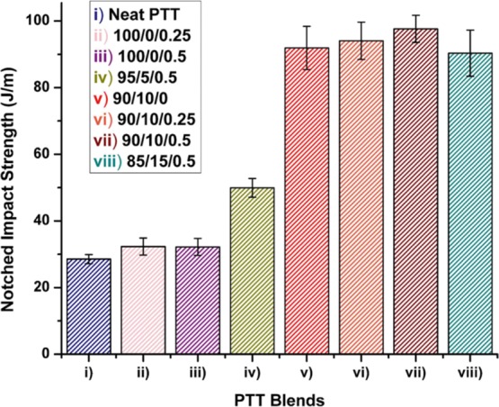
Notched impact strength of neat PTT and blends.
Figure 7.
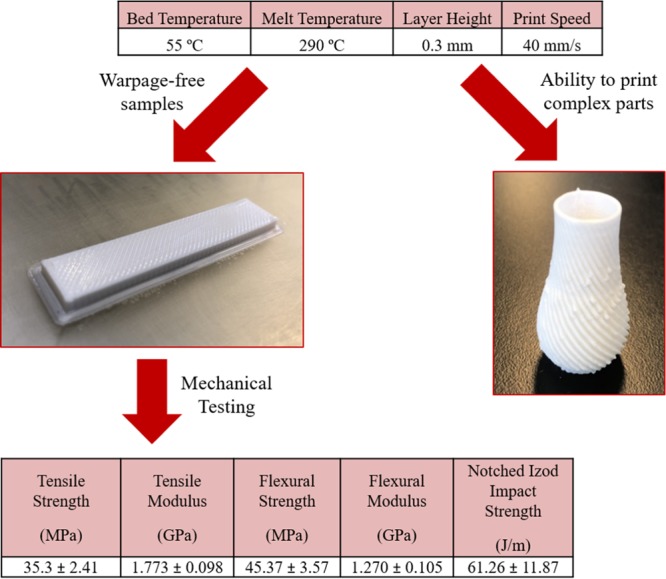
90/10/0.5 FDM samples (impact bar and small vase) printed at optimized printing parameters.
2.2.3. Differential Scanning Calorimetry
Differential scanning calorimetry (DSC) was used to analyze the melting temperature (Tm), heat of fusion (ΔHm), and degree of crystallinity, which are shown in Table S3. The melting temperature of neat PTT was the lowest at 227.87 °C, which is similar to the reported literature values.39 EBA-GMA and SA-GMA did not significantly affect the melting temperature. The heat of fusion (ΔHm) was ∼51 J/g for neat PTT and decreased to ∼46, 42, and 38 J/g for the 95/5/0.5, 90/10/0.5, and 85/5/0.5 blends, respectively. In works by Reddy et al.,39 additives to a PTT matrix also decreased the heat of fusion. This decrease is most likely caused by additives limiting the rearrangement of polymeric chains.
It is important to note that the cold crystallization temperatures were not detected on the DSC analysis of PTT and its blends. Therefore, the crystallization is based on the exothermic enthalpy peak. The degree of crystallinity decreased from a maximal value of ∼40% for neat PTT to ∼28–33% in the blends. In works completed by Najafi et al.,40 SA-GMA was found to cause long-chain branched polymer structures in PLA blends, which disrupted the ability of the polymer chains to pack closely, decreasing crystallization.40 EBA-GMA possesses similar effects in interrupting the crystallization process of PTT, which also contributed to reducing the overall crystallinity of the blends.
The degree of crystallinity is less predictable via DSC analysis for the 3D printed part as the crystallization can vary during the printing process. It has been discussed that the crystallization rates for parts made by FDM are more impacted by (1) thermodynamic stability of the materials, (2) print resolution, and (3) bonding resultant of macroscopic fusion, followed by molecular diffusion.41 These factors can be adjusted to change the crystallinity of the samples. By reducing the crystallinity of the samples, the warpage and distortion of the 3D printed part can be reduced.41 Polymers with high crystallinity distort and warp more during FDM because of polymer chain condensation when forming crystalline regions, which causes the layers to shrink and pull up from the build platform.13 An additional issue was the nonuniform cooling in the part because of the lack of a regulated chamber temperature in the tabletop 3D printer. Nonuniform cooling throughout the part can cause stress imbalances in the part, contributing to warpage. Neat PTT FDM samples exhibited the worst warpage because of the higher degree of crystallinity. The reduced crystallinity is also corroborated with the polarized optical microscopy (POM) results as shown in Figure 4, where a drastic reduction in spherulite size was observed in the POM images. The blends still experienced warpage apart from the printable 90/10/0.5 blend. This indicated that other factors are also responsible for the printability of the material. Most polymers with high crystallinity will experience issues while printing warpage-free parts. The addition of additives to modify the crystalline regions can be crucial for successful printing, as can be seen in this work with PTT.
Figure 4.
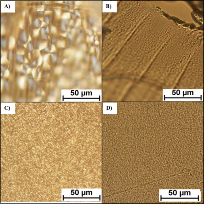
POM microphotographs of injection molded (as discussed in the Materials and Methods section) for samples of (a) neat PTT, (b) 95/5/0.5, (c) 90/10/0.5, and (d) 85/15/0.5 blends.
2.2.4. Polarized Optical Microscopy
Crystallization was also investigated with POM. Neat PTT was found to exhibit a two-dimensional spherulite structure, where the distinctive pattern shown in Figure 4a is called a Maltese cross-extinction pattern.42,43 Large spherulite sizes were present in the neat PTT, with an average size of ∼26 μm.
The addition of SA-GMA to a polymer is known to increase the molecular weight of the new blend through the reactive extrusion process.27,44 The increase in molecular weight may have resulted in decreased spherulite size because of the increase in nucleation density.43 This is only one possible explanation for the results obtained. Another suggested reason for reduced spherulite size may have resulted from the increase in molecular weight, which hinders the chain mobility of the macromolecular structure and prevents spherulite growth.43 The resulting reduced spherulite regions and smaller crystals can be seen in Figure 4 in all the blends, where spherulite sizes were reduced to a minimum of ∼2.8% of the original neat PTT size (Table S4).
As discussed in the Differential Scanning Calorimetry section, reduced crystallinity is very important for successful printing. The reductions in spherulite size and percent crystallinity contributed to the reduction of warpage in the 90/10/0.5 blend. Smaller crystalline regions result in a reduction in polymer chain movement during cooling, which in turn reduces the stresses pulling the sample off the build platform.13 Studies have been done on the effect of crystallization on injection-molded samples and the same principles can be applied. Chang and Tsaur discuss that shrinkage, warpage, and shrink marks are correlated with the crystallization characteristics of a polymer during injection molding.45
2.2.5. Rheology
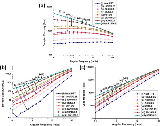
Rheological analysis was performed on the PTT blends. Figure 5a,b,c presents the complex viscosity, storage modulus, and loss modulus of the PTT blends as a function of angular frequency, respectively. The melt flow behavior of neat PTT exhibited almost Newtonian flow behavior with slight shear thinning at high angular frequencies. The blends gradually changed from Newtonian flow to shear thinning behavior with increasing additive content. This showed that the viscosity of the PTT blends is more sensitive to high shearing action upon melting in comparison to neat PTT. The 85/15/0.5 blend experienced the greatest complex viscosity at lower frequencies, which is due to the highly viscous nature of EBA-GMA. SA-GMA also acted to increase the viscosity of the blends. The increase of viscosity with increasing EBA-GMA/SA-GMA content is consistent with the MFI results (see Table S1). The functionalized epoxy groups available in EBA-GMA and SA-GMA are highly reactive at high temperatures. Chang et al.18 found that the phase compatibility and grafting reactions are more effective when both EBA-GMA and SA-GMA are used, which resulted in higher melt viscosity and impact strength in PLA/PBT blends.
Figure 5.
Frequency sweep for PTT and blends to determine (a) complex viscosity, (b) storage modulus, and (c) loss modulus.
The storage modulus and loss modulus of PTT increased after incorporating EBA-GMA and SA-GMA. This can be related to the formation of the PTT-g-EBA-GMA copolymer. Similar observations were reported by You et al. where the storage moduli of PET doubled with the presence of SA-GMA or EBA-GMA individually.17
Complex viscosity is an important factor in the printability of a material. Polymers with very high viscosities have difficulties in printing as there are issues with the extrusion of the material. This can lead to inconsistent flow from the nozzle or jamming. PTT blends with complex viscosities below ∼3000 Pa s at low angular frequencies had better flow through the printing nozzle. This issue led to the inability to print the 85/15/0.5 blend because of poor flowability. Shear rates during FDM are typically quite high;46 therefore, the complex viscosity in the optimal 90/10/0.5 blend during FDM is likely closer to ∼800 Pa s.
2.3. FDM of PTT-Based Blends
2.3.1. Printability of Neat PTT and Blends
The 90/10/0.5 blend was the only successful blend at printing warpage free, complete samples, as can be seen in Figure 7. The other blends experienced issues with flowability and warpage, as presented in Figure 6. Warpage was evaluated by visual inspection, and samples were determined to have warped if detachment from the printing bed was seen. Often warped samples could not be completed because of issues with complete detachment from the bed and were not analyzed for their mechanical performances. Printing parameters such as printing speed, bed temperature, nozzle temperature, and layer height were manipulated within the Lulzbot Taz 6’s capabilities to reduce warpage of these materials. A systematic experiment into variations in these parameters was performed with neat PTT to determine the optimal ranges of these parameters. The ranges were then refined for each blend to find the optimal values. On the basis of these observations, the range of printing speeds investigated was 20–40 mm/s, bed temperature was 40–70 °C, nozzle temperature was 270–290 °C, and layer height was 0.3–0.5 mm. All other printing parameters were kept constant. Some success was found in this, especially in the 95/5/0.5 blend; however, issues were still found in larger prints (such as for tensile and flexural bars). A common issue experienced with warping samples is detachment from the bed during printing, which results in incomplete samples. Warpage in these samples, as found in works by Fitzharris et al.,13 was a result of cooling conditions which caused the polymer chains to be pulled together to form a more dense crystalline region which leads to shrinkage and warpage. Less crystalline polymers such as PLA and amorphous polymers such as ABS are less affected by this.13
The blends with only SA-GMA exhibited issues with swelling and delamination between layers. Swelling of an extrudate, also referred to as the Barus effect, can be caused by a number of reasons, including the mobility of polymer molecules, their bulkiness, the temperature at the nozzle, and the cooling process of the extrudate.47 Work by Kishi and Iizuka47 indicated die swelling from extrusion processing, which estimated that similar effects were found within the extrusion through a FDM nozzle. The addition of EBA-GMA appeared to reduce swelling as it was not observed in other blends. The 85/15/0.5 blend had poor flowability through the nozzle and therefore could not print complete parts without jamming.
2.3.2. Printability of the 90/10/0.5 Blend
The 90/10/0.5 blend was successful at printing both mechanical testing bars and a complex part (a 4.5 cm tall ridged vase); however, this blend could only print successfully under the specific set of printing parameters shown in Figure 7. Changes in these parameters resulted in warpage. A brim was essential for printing, which is commonly used for semicrystalline, warpage-prone polymers, such as in the FDM of polypropylene.48 This increased the surface area of the initial layer and allowed for better adhesion of the samples to the bed. Another essential print setting was the cooling fan rate to be set to 5%. Fans at a higher rate caused the sample to cool too quickly, which developed stresses in the part and influenced the crystallization rate, which resulted in warpage.
The parameters shown in Figure 7 are the parameters commonly investigated to optimize printing.49−51 Melt temperature was the most crucial parameter and most of the success was found at 290 °C. Nozzle temperatures below this resulted in issues with inconsistent flow and poor adhesion. Bed temperature is a very important factor for bed/part adhesion. Spoerk et al.52 found that a bed temperature slightly higher than the material’s glass-transition temperature (Tg) is the optimal bed temperature for printing. PTT’s Tg is in the range of 45–55 °C;12 therefore, the bed temperature was set at 55 °C. Layer height was set at 0.3 mm, and the corresponding settings on Cura were manipulated to produce the nicest rasters and avoid over- and underextrusion. Print speed was set at 40 mm/s, very high print speed resulted in uneven, broken rasters, and very slow speed increased warpage and delamination as it allowed for layers to cool completely before bonding to the next layer. The raster angles were chosen to be 45° and 135°, alternating each layer in a rectilinear fill pattern. Alternating raster angles are often set at 90° to each other to maximize the material fill and are set to avoid long raster lengths to reduce the cooling time between adjacent rasters laid down.30 As shown in Figure 7, the combination of the 90/10/0.5 blend composition and these optimized parameters resulted in parts with good dimensional stability and excellent bed adhesion. This particular blend was able to successfully print both mechanical testing bars and a complex part (a 4.5 cm tall ridged vase) as presented in Figure 7.
An essential component of FDM is optimization of printing parameters that generally needs to be redone for every material and printer combination. The parameters that were observed to have significant effects were bed and melt temperature, layer height, and print speed. For warpage-prone parts, investigating other factors might be necessary to make the polymer printable. Without the reduction of cooling rate through decreased fan, or increased adhesion to the bed through adding a brim, PTT would have been unprintable. For successful printing, all these factors must be considered.
2.3.3. Mechanical Properties of FDM Samples
Test samples were printed from the 90/10/0.5 blend using FDM technology and the results are shown in Figure 7. Most of the FDM properties were reduced to approximately half of their injection-molded counterparts. For example, flexural strength in FDM parts reduced to 53% of the injection-molded value. Reductions in properties have been observed in other FDM works, such as in the work by Tuan Rahim et al., which focused on printing of PA 12.10 They observed a reduction of 25% in flexural strength between injection-molded and FDM-prepared parts.10 This is attributed to the method of production, as FDM does not create uniform, solid parts. The presence of voids between layers contributes to the decreased mechanical properties as there is reduced interlayer bonding. Thermal stresses appear between rasters because of the differences in temperature when bonding, which allow fractures to propagate easier during impact testing.53 Because of the limitations in maximum nozzle temperature on the printer, investigations into increased nozzle temperatures to attempt to reduce these voids could not be done, limiting the improvements available in mechanical properties. However, the notched impact strength of the PTT blend still presented a strong value of ∼61 J/m. The tensile strength of the 90/10/0.5 blend is comparable to that of the other printable polyesters (recycled PET),14 as shown in Table S5, with regard to tensile strength, which is only half of PLA’s FDM tensile strength.21 In terms of impact strength, the 90/10/0.5 blend is comparable to ∼187% greater PLA’s strength depending on the printing conditions.21 This PTT blend exhibited properties comparable to other printable polymers and exhibits good toughness.
2.3.4. Scanning Electron Microscopy
A scanning electron microscopy (SEM) analysis of the impact fracture surfaces was performed on injection-molded neat PTT and the 90/10/0.5 blend, and the FDM 90/10/0.5 blend (shown in Figures S1a,b and 8, respectively). The neat PTT sample showed ridges (as indicated by the arrow in Figure S1a) and flat sections on the fractured impact surface, which confirm its brittle nature. The injection-molded 90/10/0.5 blend showed rougher surface morphology with fewer ridges.
Figure 8.
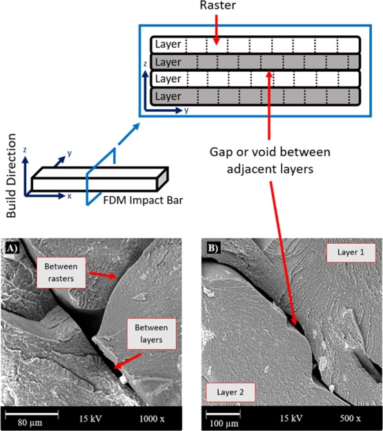
Schematic of layers and corresponding gaps/voids in a FDM part with micrographs taken at 15 kV of the fractured impact surface of 90/10/0.5 FDM samples displaying (a) raster adhesion and (b) layer adhesion.
The surface of the FDM blend sample appeared similar to its injection-molded counterpart. As shown in Figure 8, FDM-printed parts are deposited layer by layer in a vertical build direction. Depending on material and printing properties, and interlayer cohesion, gaps or voids can develop between layers. In Figure 8a,b, the intersections between layers and rasters can be seen. Large gaps were seen at these intersections, which indicated poor cohesion between layers, which is likely due to the decreased mechanical properties. Gaps between layers are common in many 3D printed samples. In fact, Weng et al. stated that the gaps are unavoidable without further work in FDM of ABS.54 Cohesion can be improved through altering the melt temperature. Benwood et al. found that increasing the melt or nozzle temperature resulted in decreased void size between layers. For maximum diffusion and cohesion of a material between layers, the extruded filament needs to be hot enough to partially melt the preceding layer. Rapid cooling, particularly in the outer shell region, also resulted in larger voids between layers.21 The samples printed in this study are printed at the maximum temperature of the Lulzbot Taz 6; therefore, further investigation of increased melt temperature could not be achieved.
3. Conclusions
In this work, PTT was able to 3D print complete and warpage-free samples because of the modifications made in processing and printing parameters, and with the assistance of additives. The successful completion of samples with FDM PTT using these methods confirms the potential ability of these techniques to help improve the printability of other difficult-to-print polymers. The addition of a CE and an impact modifier was crucial to improve the printability of PTT. The use of these additives was a proof of concept that suggested that traditional strategies used in injection molding can be transposed to FDM. Successful printing was dependent on a number of factors changed by these additives, including (1) a reduction in MFI by 84% from the neat PTT value, (2) a change from spherulites to crystals with a 93.4% size reduction from neat PTT (less crystalline polymers experience less warpage), and (3) a reduction in the degree of crystallinity by 18% from that of the neat polymer. The printed samples possessed tensile strength similar to 3D printed PET and impact strength similar to 3D printed PLA, at 35.3 MPa and 61.3 J/m, respectively. This work represents a new potential use for PTT in the AM field. As a partially biobased polymer, PTT has strong promise as a more sustainable material to be used in FDM as compared to complete petroleum-based engineering thermoplastics.
4. Materials and Methods
4.1. Materials
PTT, trademarked as Sorona (Dupont, Delaware, USA), is an engineering thermoplastic with 37% biobased content12 and a molecular weight of 56 300 g/mol.26 PTT pellets were used as the neat polymer matrix to generate filaments for FDM. Poly(styrene-acrylic-co-glycidyl methacrylate) (SA-GMA), trademarked as Joncryl 4368 (BASF, Ludwigshafen, Germany), was used as a CE because of its reactive epoxy group. The molecular weight of SA-GMA is 6800 g/mol.27 The reactive epoxy group is contained within the glycidyl methacrylate segment of the molecule at 49.8 wt %. According to the literature, the epoxy equivalent weight for this molecule is 285 g/mol.17 Poly(ethylene-n-butylene-acrylate-co-glycidyl methacrylate) (EBA-GMA), commonly named Elvaloy PTW (Dupont, Delaware, USA), was used in combination with PTT as an impact modifier. EBA-GMA contains 5.25 wt % glycidyl methacrylate. Because SA-GMA contains nearly 10 times more glycidyl methacrylate by weight, it is inferred that SA-GMA is 10 times more reactive. Further details are discussed in the literature by You et al.17
4.2. Blend Preparation
PTT was dried at 80 °C for 24 h prior to processing, such that the moisture content was below 0.5%. Moisture was analyzed with a Sartorius AG Moisture Analyzer (Gottingen, Germany). Minimal moisture was very important when processing PTT to reduce the risk of hydrolysis degradation during processing. After drying, SA-GMA was powdered and physically mixed before processing.
4.3. Processing Conditions
4.3.1. Filaments
Blended materials were fed in the hopper of a Leistritz-Micro-27 (Nuremberg, Germany) twin screw extruder under a corotating configuration. The processing temperature was 250 °C with a screw speed of 100 rpm. After leaving the die, the filaments ran through a cold water bath and were collected and dried. The complete extent of the reaction between the epoxy side chains and PTT is unknown but could be investigated in further works.
4.3.2. Injection-Molded Samples
Filaments were pelletized and dried to a moisture content of ≤0.2%. Injection-molded samples were processed in an Arburg AllRounder 77 Ton Co-Injection Molding Machine (Loßburg, Germany). Parameters used were a melt temperature of 240, a mold temperature of 80 °C, and a hold time of 20 s.
4.3.3. FDM Samples
FDM testing samples were modeled using CAD on SolidWorks by Dassault Systems (Vélizy-Villacoublay, France). Cura LulzBot Edition (2.6.69) software was used to run the 3D printer. Samples were printed on a LulzBot Taz 6 printer (Loveland, USA) with a borosilicate glass/polyethyleneimine build plate and a 0.50 mm diameter nozzle. The same configuration has been implemented in previous works.55 Printing parameters, such as nozzle and build platform temperatures, print speed, and layer height, varied depending on the blend compositions. Other parameters were kept constant throughout printing, such as 100% infill density, 5% fan cooling rate, orientation of parts along the x-axis, and a raster angle of 45°. Various bed coatings, such as tape and glue, were investigated, but most of the success was found on a naked bed.
4.4. Mechanical Testing
4.4.1. Tensile and Flexural Testing
Tensile and flexural samples were tested on a Universal testing machine model 3382 (Instron, Massachusetts). Tensile and flexural tests were carried out according to ASTM D638 standard type IV and ASTM D790, respectively. Tensile tests were carried out with samples placed between pneumatic grips at strain rates of 50 mm/min for injection-molded parts and 5 mm/min for FDM parts, as per time requirements of the standard. Flexural tests were carried out with a span length of 52 mm and a cross head speed of 14 mm/min. The same flexural testing procedure was used on other 3D printed samples from this lab.REF55
4.4.2. Impact Testing
Notched Izod impact testing was conducted, according to ASTM D256, on a Zwick/Roell HIT25P impact tester (Ulm, Germany) with a hammer capacity of 2.75 J.
4.5. Physical Analysis
4.5.1. Melt Flow Index
MFI was used as a relative estimate of the viscosity of the samples. Materials (6–8 g) were placed in the heating chamber of a Qualitest melt flow indexer (Qualitest, Connecticut, USA) in accordance with ASTM D1238 and tested at 250 °C.
4.5.2. Average Diameter
The diameter of the strands was measured 10 times at intervals along a 50 cm section of the filament with calipers and averaged.
4.5.3. Density
An electronic densimeter (Alfa Mirage, Osaka, Japan) was used to measure the density of the samples. Each blend was tested three times with different samples and averaged.
4.6. Characterization
4.6.1. Differential Scanning Calorimetry
DSC Q200 (TA Instruments, Delaware, USA) was used with a nitrogen flow rate of 50 mL/min to perform heat–cool–heat cycle analysis. The cycles were performed from 0 to 250 °C at a rate of 10 °C/min, and data were taken from the second heating cycle. The degree of crystallinity was calculated from eq 1 below
| 1 |
where ΔHm is the heat of fusion, Wf is the weight content of PTT, and ΔHmo is the heat of fusion for 100% crystalline PTT (30 kJ/mol)28 (which is equivalent to 145.5 J/g). The PTT content was 1 for the neat polymer and varies between 0.95, 0.90, and 0.85 for the respective blends.
4.6.2. Rheology
Rheological analysis was completed on a Modular Compact Rheometer 302 (Anton Paar, Graz, Austria) to determine complex viscosity, storage modulus, and loss modulus. The samples (1 mm thick, 12 mm in diameter) were tested at 250 °C in a nitrogen gas environment with the frequency sweep test with an angular frequency of 0.1–100 rad/s using a parallel plate geometry.
4.6.3. Microscopy
POM (Nikon, New York, USA) was used to observe the crystalline structures within the samples. Samples were microtomed to a thickness of 1 μm, before being imaged. This resulted in the use of injection-molded samples to ensure consistent and complete samples. SEM (Phenom-world ProX, Eindhoven, Netherlands) analysis was performed on the impact-fractured surface. The SEM images were formed with a 10 and 15 kV acceleration voltage and zoom from 500 to 5000 times.
Acknowledgments
The authors are thankful to (i) Ontario Ministry of Economic Development, Job Creation and Trade ORF-RE09-078 (Project no. 053970); (ii) the Ontario Ministry of Agriculture, Food and Rural Affairs (OMAFRA), University of Guelph, Bioeconomy Industrial Uses Research Program Theme Project no. 030252; and the (iii) Natural Sciences and Engineering Research Council (NSERC) Canada Discovery Grants Project no. 400320 for their financial support.
Supporting Information Available
The Supporting Information is available free of charge on the ACS Publications website at DOI: 10.1021/acsomega.9b02795.
Properties of neat PTT and PTT blend filaments; mechanical properties of injection-molded neat PTT and blends; DSC analysis of neat PTT and blends (melting temperature, ΔHm, and degree of crystallinity); average spherulite size of neat PTT and its blends; comparison of FDM mechanical properties of different polymers; and micrographs taken at 10 kV of the fractured impact surface of neat PTT and 90/10/0.5 injection-molded samples (PDF)
Author Contributions
This manuscript was written through contributions from all authors. All authors have given approval to the final version of the manuscript.
The authors declare no competing financial interest.
Supplementary Material
References
- Bogue R. 3D Printing: The Dawn of a New Era in Manufacturing?. Assem. Autom. 2013, 33, 307–311. 10.1108/aa-06-2013-055. [DOI] [Google Scholar]
- Wong K. V.; Hernandez A. A Review of Additive Manufacturing. ISRN Mech. Eng. 2012, 2012, 1–10. 10.5402/2012/208760. [DOI] [Google Scholar]
- Wang X.; Jiang M.; Zhou Z.; Gou J.; Hui D. 3D Printing of Polymer Matrix Composites: A Review and Prospective. Compos. Part B Eng. 2017, 110, 442–458. 10.1016/j.compositesb.2016.11.034. [DOI] [Google Scholar]
- Murphy C. A.; Collins M. N. Microcrystalline Cellulose Reinforced Polylactic Acid Biocomposite Filaments for 3D Printing. Polym. Compos. 2018, 39, 1311–1320. 10.1002/pc.24069. [DOI] [Google Scholar]
- Nguyen N. A.; Bowland C. C.; Naskar A. K. Mechanical, Thermal, Morphological, and Rheological Characteristics of High Performance 3D-Printing Lignin-Based Composites for Additive Manufacturing Applications. Data Br. 2018, 19, 936–950. 10.1016/j.dib.2018.05.130. [DOI] [PMC free article] [PubMed] [Google Scholar]
- Idrees M.; Jeelani S.; Rangari V. Three-Dimensional-Printed Sustainable Biochar-Recycled PET Composites. ACS Sustain. Chem. Eng. 2018, 6, 13940–13948. 10.1021/acssuschemeng.8b02283. [DOI] [Google Scholar]
- Ertane E. G.; Dorner-Reisel A.; Matner V.; Baran O.; Welzel T.; Svoboda S. Processing and Wear Behaviour of 3D Printed PLA Reinforced with Biogenic Carbon. Adv. Tribol. 2018, 2018, 1763182. 10.1155/2018/1763182. [DOI] [Google Scholar]
- Kucherov F. A.; Gordeev E. G.; Kashin A. S.; Ananikov V. P. Three-Dimensional Printing with Biomass-Derived PEF for Carbon-Neutral Manufacturing. Angew. Chem., Int. Ed. 2017, 56, 15931–15935. 10.1002/anie.201708528. [DOI] [PubMed] [Google Scholar]
- Pickering K.; Stoof D. Sustainable Composite Fused Deposition Modelling Filament Using Post-Consumer Recycled Polypropylene. J. Compos. Sci. 2017, 1, 17. 10.3390/jcs1020017. [DOI] [Google Scholar]
- Tuan Rahim T. N. A.; Abdullah A. M.; Akil H. M.; Mohamad D.. Comparison of Mechanical Properties for Polyamide 12 Composite-Based Biomaterials Fabricated by Fused Filament Fabrication and Injection Molding. AIP Conference Proceedings, 2016; Vol. 1791.
- Nguyen N. A.; Naskar A. K.; Keum J. K.; Littrell K. C.; Meek K. M.; Bowland C. C.; Barnes S. H.; Barnes S. H.; Bowland C. C.; Meek K. M.; et al. A Path for Lignin Valorization via Additive Manufacturing of High-Performance Sustainable Composites with Enhanced 3D Printability. Sci. Adv. 2018, 4, eaat4967 10.1126/sciadv.aat4967. [DOI] [PMC free article] [PubMed] [Google Scholar]
- Kurian J. V.Sorona Polymer: Present Status and Future Perspectives. In Natural fibers, Biopolymers, and Biocomposites; Mohanty A. K., Misra M., Drzal L. T., Eds.; Taylor & Francis, 2005; pp 503–530. [Google Scholar]
- Fitzharris E. R.; Watanabe N.; Rosen D. W.; Shofner M. L. Effects of Material Properties on Warpage in Fused Deposition Modeling Parts. Int. J. Adv. Manuf. Technol. 2017, 95, 2059–2070. 10.1007/s00170-017-1340-8. [DOI] [Google Scholar]
- Zander N. E.; Gillan M.; Lambeth R. H. Recycled polyethylene terephthalate as a new FFF feedstock material. Addit. Manuf. 2018, 21, 174–182. 10.1016/j.addma.2018.03.007. [DOI] [Google Scholar]
- Gnanasekaran K.; Heijmans T.; van Bennekom S.; Woldhuis H.; Wijnia S.; de With G.; Friedrich H. 3D Printing of CNT- and Graphene-Based Conductive Polymer Nanocomposites by Fused Deposition Modeling. Appl. Mater. Today 2017, 9, 21–28. 10.1016/j.apmt.2017.04.003. [DOI] [Google Scholar]
- Bai H.; Zhang Y.; Zhang Y.; Zhang X.; Zhou W. Toughening Modification of PBT/PC Blends with PTW and POE. J. Appl. Polym. Sci. 2006, 101, 54–62. 10.1002/app.22436. [DOI] [Google Scholar]
- You X.; Snowdon M. R.; Misra M.; Mohanty A. K. Biobased Poly(Ethylene Terephthalate)/Poly(Lactic Acid) Blends Tailored with Epoxide Compatibilizers. ACS Omega 2018, 3, 11759–11769. 10.1021/acsomega.8b01353. [DOI] [PMC free article] [PubMed] [Google Scholar]
- Chang B. P.; Mohanty A. K.; Misra M. Tuning the Compatibility to Achieve Toughened Biobased Poly(Lactic Acid)/Poly(Butylene Terephthalate) Blends. RSC Adv. 2018, 8, 27709–27724. 10.1039/c8ra05161e. [DOI] [PMC free article] [PubMed] [Google Scholar]
- Rasselet D.; Caro-Bretelle A. S.; Taguet A.; Lopez-Cuesta J. M. Reactive Compatibilization of PLA/PA11 Blends and Their Application in Additive Manufacturing. Materials 2019, 12, 485. 10.3390/ma12030485. [DOI] [PMC free article] [PubMed] [Google Scholar]
- Torres J.; Cole M.; Owji A.; DeMastry Z.; Gordon A. P. An Approach for Mechanical Property Optimization of Fused Deposition Modeling with Polylactic Acid via Design of Experiments. Rapid Prototyp. J. 2016, 22, 387–404. 10.1108/rpj-07-2014-0083. [DOI] [Google Scholar]
- Benwood C.; Anstey A.; Andrzejewski J.; Misra M.; Mohanty A. K. Improving the Impact Strength and Heat Resistance of 3D Printed Models: Structure, Property, and Processing Correlationships during Fused Deposition Modeling (FDM) of Poly(Lactic Acid). ACS Omega 2018, 3, 4400–4411. 10.1021/acsomega.8b00129. [DOI] [PMC free article] [PubMed] [Google Scholar]
- Anitha R.; Arunachalam S.; Radhakrishnan P. Critical Parameters Influencing the Quality of Prototypes in Fused Deposition Modelling. J. Mater. Process. Technol. 2001, 118, 385–388. 10.1016/s0924-0136(01)00980-3. [DOI] [Google Scholar]
- Zarringhalam H.; Hopkinson N.; Kamperman N. F.; de Vlieger J. J. Effects of Processing on Microstructure and Properties of SLS Nylon 12. Mater. Sci. Eng. A 2006, 435–436, 172–180. 10.1016/j.msea.2006.07.084. [DOI] [Google Scholar]
- Sezer H. K.; Eren O. FDM 3D Printing of MWCNT Re-Inforced ABS Nano-Composite Parts with Enhanced Mechanical and Electrical Properties. J. Manuf. Process. 2019, 37, 339–347. 10.1016/j.jmapro.2018.12.004. [DOI] [Google Scholar]
- Song R.; Clemon L.; Telenko C. Uncertainty and Variability of Energy and Material Use by Fused Deposition Modeling Printers in Makerspaces. J. Ind. Ecol. 2019, 23, 699. 10.1111/jiec.12772. [DOI] [Google Scholar]
- Nagarajan V.; Mohanty A. K.; Misra M. Reactive Compatibilization of Poly Trimethylene Terephthalate (PTT) and Polylactic Acid (PLA) Using Terpolymer: Factorial Design Optimization of Mechanical Properties. Mater. Des. 2016, 110, 581–591. 10.1016/j.matdes.2016.08.022. [DOI] [Google Scholar]
- BASF Corporation . Joncryl ADR-4368C; Florham Park: New Jersey, 2008. [Google Scholar]
- Pyda M.; Boller A.; Grebowicz J.; Chuah H.; Lebedev B. V.; Wunderlich B. Heat capacity of poly(trimethylene terephthalate). J. Polym. Sci. Part B Polym. Phys. 1998, 36, 2499–2511. . [DOI] [Google Scholar]
- Myllytie P.; Misra M.; Mohanty A. K. Carbonized Lignin as Sustainable Filler in Biobased Poly(Trimethylene Terephthalate) Polymer for Injection Molding Applications. ACS Sustain. Chem. Eng. 2016, 4, 102–110. 10.1021/acssuschemeng.5b00796. [DOI] [Google Scholar]
- Agarwala M. K.; Jamalabad V. R.; Langrana N. A.; Safari A.; Whalen P. J.; Danforth S. C. Structural Quality of Parts Processed by Fused Deposition. Rapid Prototyp. J. 1996, 2, 4–19. 10.1108/13552549610732034. [DOI] [Google Scholar]
- Verma R.; Bhuvanesh Y. C.; Gupta V. B. Some Studies on Melt Flow Behaviour of Poly ( Ethylene Terephthalate ). Ind. J. Fibre Text Res. 1991, 16, 39–45. [Google Scholar]
- Chung C. I.Physical Description of Single-Screw Extrusion. Extrusion of Polymers: Theory and Practice; Hanser Publishers, 2010; pp 1–47. [Google Scholar]
- Wagner J. R. Jr.; Mount E. M. III; Giles H. F. Jr.. Solidification and Cooling. Extrusion: The Definitive Processing Guide and Handbook; ScienceDirect, 2014; pp 111–120. [Google Scholar]
- Villalobos M.; Awojulu A.; Greeley T.; Turco G.; Deeter G. Oligomeric Chain Extenders for Economic Reprocessing and Recycling of Condensation Plastics. Energy 2006, 31, 3227–3234. 10.1016/j.energy.2006.03.026. [DOI] [Google Scholar]
- Al-Itry R.; Lamnawar K.; Maazouz A. Improvement of Thermal Stability, Rheological and Mechanical Properties of PLA, PBAT and Their Blends by Reactive Extrusion with Functionalized Epoxy. Polym. Degrad. Stab. 2012, 97, 1898–1914. 10.1016/j.polymdegradstab.2012.06.028. [DOI] [Google Scholar]
- Hwang S.; Reyes E. I.; Moon K.-s.; Rumpf R. C.; Kim N. S. Thermo-Mechanical Characterization of Metal/Polymer Composite Filaments and Printing Parameter Study for Fused Deposition Modeling in the 3D Printing Process. J. Electron. Mater. 2015, 44, 771–777. 10.1007/s11664-014-3425-6. [DOI] [Google Scholar]
- DuPont Packaging & Industrial Polymers . Elvaloy® Resins Product Data Sheet, 2015.
- Yuryev Y.; Mohanty A. K.; Misra M. Novel Super-Toughened Bio-Based Blend from Polycarbonate and Poly(Lactic Acid) for Durable Applications. RSC Adv. 2016, 6, 105094–105104. 10.1039/c6ra21208e. [DOI] [Google Scholar]
- Reddy J. P.; Misra M.; Mohanty A. Renewable Resources-Based PTT [Poly(Trimethylene Terephthalate)]/Switchgrass Fiber Composites: The Effect of Compatibilization. Pure Appl. Chem. 2012, 85, 521–532. 10.1351/pac-con-12-04-05. [DOI] [Google Scholar]
- Najafi N.; Heuzey M. C.; Carreau P. J. Crystallization behavior and morphology of polylactide and PLA/clay nanocomposites in the presence of chain extenders. Polym. Eng. Sci. 2013, 53, 1053–1064. 10.1002/pen.23355. [DOI] [Google Scholar]
- Srinivas V.; van Hooy-Corstjens C. S. J.; Harings J. A. W. Correlating Molecular and Crystallization Dynamics to Macroscopic Fusion and Thermodynamic Stability in Fused Deposition Modeling; a Model Study on Polylactides. Polymer 2018, 142, 348–355. 10.1016/j.polymer.2018.03.063. [DOI] [Google Scholar]
- Li G.; Wang K.; Li S.; Shi Y. Isothermal Melt Crystallization Kinetics for Poly(Trimethylene Terephthalate)/Poly(Butylene Terephthalate) Blends. J. Macromol. Sci. Part B Phys. 2007, 46, 569–580. 10.1080/00222340701257901. [DOI] [Google Scholar]
- Chen X.; Hou G.; Chen Y.; Yang K.; Dong Y.; Zhou H. Effect of molecular weight on crystallization, melting behavior and morphology of poly(trimethylene terephalate). Polym. Test. 2007, 26, 144–153. 10.1016/j.polymertesting.2006.08.011. [DOI] [Google Scholar]
- Frenz V.; Scherzer D.; Villalobos M.; Awojulu A.; Edison M.; Van Der Meer R. Multifunctional Polymers as Chain Extenders and Compatibilizers for Polycondensates and Biopolymers. Tech. Pap. Reg. Tech. Conf.—Soc. Plast. Eng. 2008, 3, 1678–1682. [Google Scholar]
- Chang R. Y.; Tsaur B. D. Experimental and theoretical studies of shrinkage, warpage, and sink marks of crystalline polymer injection molded parts. Polym. Eng. Sci. 1995, 35, 1222–1230. 10.1002/pen.760351505. [DOI] [Google Scholar]
- Ou-Yang Q.; Guo B.; Xu J. Preparation and Characterization of Poly(Butylene Succinate)/Polylactide Blends for Fused Deposition Modeling 3D Printing. ACS Omega 2018, 3, 14309–14317. 10.1021/acsomega.8b02549. [DOI] [PMC free article] [PubMed] [Google Scholar]
- Kishi N.; Iizuka H. The Barus Effect of Polymer Melts. J. Polym. Sci. Part B Polym. Lett. 1964, 2, 399–402. 10.1002/pol.1964.110020417. [DOI] [Google Scholar]
- Wang L.; Palmer J.; Tajvidi M.; Gardner D. J.; Han Y. Thermal Properties of Spray-Dried Cellulose Nanofibril-Reinforced Polypropylene Composites from Extrusion-Based Additive Manufacturing. J. Therm. Anal. Calorim. 2019, 136, 1069–1077. 10.1007/s10973-018-7759-9. [DOI] [Google Scholar]
- Fitzharris E. R.; Watanabe N.; Rosen D. W.; Shofner M. L. Effects of Material Properties on Warpage in Fused Deposition Modeling Parts. Int. J. Adv. Manuf. Technol. 2018, 95, 2059–2070. 10.1007/s00170-017-1340-8. [DOI] [Google Scholar]
- Gnanasekaran K.; Wijnia S.; de With G.; Friedrich H.; Heijmans T.; Woldhuis H.; van Bennekom S. 3D Printing of CNT- and Graphene-Based Conductive Polymer Nanocomposites by Fused Deposition Modeling. Appl. Mater. Today 2017, 9, 21–28. 10.1016/j.apmt.2017.04.003. [DOI] [Google Scholar]
- Zander N. E.; Gillan M.; Lambeth R. H. Recycled polyethylene terephthalate as a new FFF feedstock material. Addit. Manuf. 2018, 21, 174–182. 10.1016/j.addma.2018.03.007. [DOI] [Google Scholar]
- Spoerk M.; Gonzalez-Gutierrez J.; Sapkota J.; Schuschnigg S.; Holzer C. Effect of the Printing Bed Temperature on the Adhesion of Parts Produced by Fused Filament Fabrication. Plast. Rubber Compos. 2018, 47, 17–24. 10.1080/14658011.2017.1399531. [DOI] [Google Scholar]
- Sood A. K.; Ohdar R. K.; Mahapatra S. S. Parametric Appraisal of Mechanical Property of Fused Deposition Modelling Processed Parts. Mater. Des. 2010, 31, 287–295. 10.1016/j.matdes.2009.06.016. [DOI] [Google Scholar]
- Weng Z.; Wang J.; Senthil T.; Wu L. Mechanical and Thermal Properties of ABS/Montmorillonite Nanocomposites for Fused Deposition Modeling 3D Printing. Mater. Des. 2016, 102, 276–283. 10.1016/j.matdes.2016.04.045. [DOI] [Google Scholar]
- Qahtani M.; Wu F.; Misra M.; Gregori S.; Mielewski D. F.; Mohanty A. K. Experimental Design of Sustainable 3D-Printed Poly(Lactic Acid)/Biobased Poly(Butylene Succinate) Blends via Fused Deposition Modeling. ACS Sustain. Chem. Eng. 2019, 7 (17), 14460–14470. 10.1021/acssuschemeng.9b01830. [DOI] [Google Scholar]
Associated Data
This section collects any data citations, data availability statements, or supplementary materials included in this article.


