Abstract
Accuracy and precision in dosimetry is crucial in studies involving animal models. Small animal dosimetry, in particular for protracted exposures to non uniform radiation fields is particularly challanging. We have developed a novel in-vivo dosimeter based on glass encapsulated TLD rods. These encapsulated rods can be injected into mice and used for validating doses to an individual mouse in a protracted irradiation scenario where the mouse is free to move in an inhomogenous radiation field. Data from 30 irradiated mice shows a reliable dose reconstruction within 10% of the nominal delivered dose.
Keywords: TLD, encapsulation, dose validation
Introduction
Accuracy and precision in both dosimetry and irradiation experiments is crucial in studies involving animal models [1]. While dose verification in radiotherapy has received much attention and can be partially translated to animal studies (in particular for larger animals like non human primates [2]), placing external radiation monitors on smaller animals, like mice, provides challenges, in particular when animals are free to move in the irradiator during protracted irradiations.
We have recently developed an ultra low dose rate irradiator for modeling fallout and other environmental contamination exposures. In the VADER (Variable Dose rate External irradiatoR) [3], mice are placed in a large cage, between movable 137Cs, sources and are exposed to gamma rays at dose rates of 0.1 to 1.2 Gy/day over a period of several weeks, resulting in total doses on the order of 2 - 10 Gy. Clearly in such a case, per-mouse dose validation is critical and restraining mice or providing an external dosimeter (that can be chewed off) are not viable options.
A solution to this problem was originally implemented by Sicel Technologies [4]. The Dose Verification System (DVS), consists of an injectable, encapsulated, microMOSFET dosimeter that can be read remotely. While good results were obtained with this system [5] it was discontinued in 2010 and is no longer commercially available.
This manuscript describes our approach to implementing an injectable dosimeter (Fig. 1) based on TLD-100 thermoluminescent dosimeter material, encapsulated in a biocompatible, transparent and heat-stable glass capsule. The TLD material is protected from biofluids within the mouse which may degrade its performance. The encapsiulated TLD rod is slightly smaller than a standard Radio Frequency Identification (RFID) transponder and can thus be injected using standard protocols. Unlike the DVS system, the encapsulated TLD must be surgically removed prior to readout and can thus only give an integrated dose.
Figure 1:
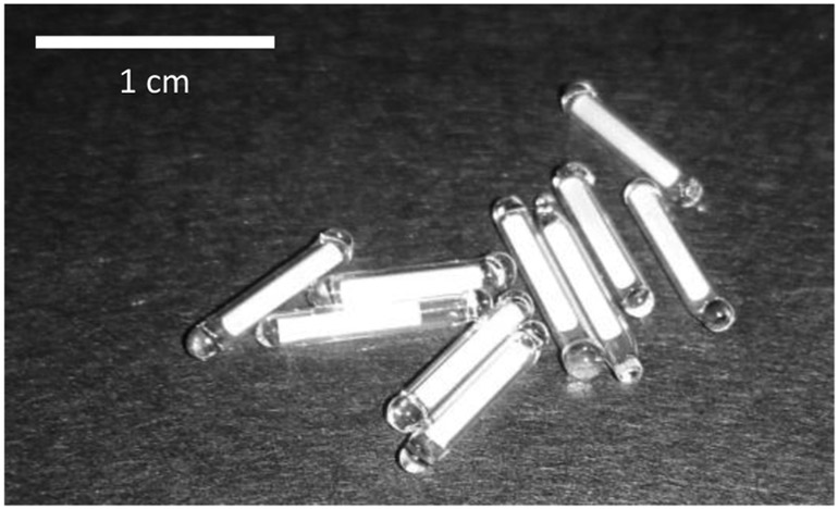
Photo of encapsulated TLD rods.
As described below, the encaspulation does not interfere with the TLD readout procedure or, importantly, with the annealing, which requires heating to 400 °C.
In this work we selected to use TLD-100 over, similarly sized, microMOSFETs as only wired microMOSFETS are commercially available at this time. Furthermore, MOSFETs are limited to a total lifetime dose of 80-200 Gy [6] after which the sensor needs to be replaced. TLDs, on the other, lose sensitivity over accumulated doses of thousands of Gy (Cai et al reported twofold decrease in response after an accumulated dose of 10 kGy [7]) but can be recalibrated every few hundred Gy to account for this.
We present here the characterisation and calibration of the encapsulated TLD chips and demonstrate their use for in-vivo dose verification in mice.
Materials and Methods
Mouse irradiations and handling were performed under Columbia University IACUC protocol AC-AAAQ2410.
Encapsulation and preparation of TLD rods
One hundred TLD rods (TLD-100; 1 mm diameter, 6 mm long, from the same batch) were obtained from Thermo Fisher Scientific (Waltham, MA). Encapsulation was performed by King Precision Glass (Claremont, CA): Briefly, one end of a borosilicate glass tube (KG-33 glass; ID 1.1±0.05 mm; OD 1.5±0.05 mm) was sealed using a propane-oxygen flame. The TLD was inserted and the tube mounted in a heat sink. The free end of the tube was then heated while pulling. After the tube necked off, more heat was applied to finish the seal.
As it was expected that the glass encapsulation may reduce the amount of light detected, changing the calibration with respect to standard TLD rods, the TLDs were calibrated after the encapsulation.
Prior to each use, the encapsulated TLDs were baked and annealed as per the vendor recommendations (Nominally 1 h at 400 °C followed by 2 h cooldown to 100°C and 2 h at 100 °C) using an Isotemp programmable muffle furnace (Thermo Fisher Scientific).
Animal husbandry
For in vivo irradiations, male 7 week old C57BI/6J “cage mate” mice were purchased from Charles River Laboratories and kept at the Columbia University Irving Medical Center’s animal facility for one week of adaptation. Encapsulated TLDs were injected when mice were 8 weeks of age and the study performed starting at 9 weeks. Animals were provided with food and water ad libitum and kept on a 12:12 hour light-dark schedule.
Radiation dosimeter injection
Anaesthesia was induced with 2% isoflurane delivered in 100% oxygen for <3 min before the implantation procedure. The encapsulated TLD rods (one per mouse) were placed in a 12 gauge needle coupled with a needle injector (Allflex, Irving, TX) and administered by subcutaneous injection in the dorsal neck. Following implantation mice were monitored up to 48 hours for complications.
Following irradiation, mice were observed for 48h and the TLDs surgically removed.
Irradiation procedures
For calibration, the rods were placed in an ABS (Acrylonitrile Butadiene Styrene) plastic holder and placed at the bottom of a gammacell 137Cs irradiator (Canada). Dose rate in the gammacell is tested annually and was between 0.57 and 0.75 Gy/min (depending on sample position) for the measurements reported below.
Mice were irradiated in the same gammacell irradiator, using a standard pie irradiation enclosure. For mouse irradiations, the TLDs were higher in the irradiator (farther from the bottom source), resulting in a lower dose rate (0.57 Gy/min), as verified using a NIST (National Institute of Standards and Technology) traceable Radcal Accudose ionization chamber (10×6-6; Radcal Corp., Monrovia, CA).
Readout
The TLDs were kept at room temperature for a few days (up to two weeks) after irradiation to allow decay of the low temperature glow peaks. The rods were read using a Harshaw 2500 TLD reader (Thermo Fisher Scientific). Most experiments used a heating profile consisting of a 5°C/sec ramp up to 300°C followed by a short hold at 300 °C and cool down to 50°C.
Collected current on the photomultiplier was integrated starting at a temperature of 180 °C to eliminate any residual low temperature, time dependant, glow peak.
Tracking TLD rods
As the response of TLD rods is highly variable, even between rods from the same batch, each TLD rod was assigned a unique code and tracked throught this work. Rods were stored either individually, in labled eppendorf tubes, or in a custom designed aluminum tray (Protolabs, Maple Plain, MN), also used for the anneal process.
Results
Calibration curves
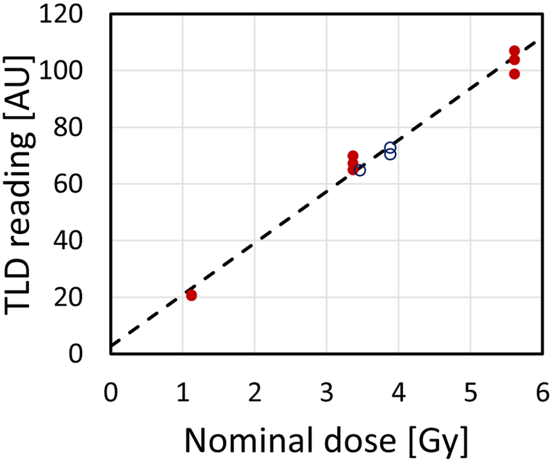
Calibration curves were generated individually for each encapsulated TLD rod by performing three consecutive irradiation-read-anneal cycles, at each of the doses 1, 3 and 5 Gy. Independent linear fit parameters were obtained for each rod using linear regression, as implemented by the Microsoft Excel (Redmond, WA) SLOPE(known_y’s, known_x’s) and INTERCEPT(known_y’s, known_x’s) functions. A sample fit is shown in Fig. 2. To reconstruct dose, the difference between the intercept and light yield was divided by the slope.
Figure 2:
Sample calibration curve (dashed line) for one of the encapsulated TLD rods. The closed symbols were used to calculate the curve. The Open symbols are subsequent in-vivo measurements using the same rod.
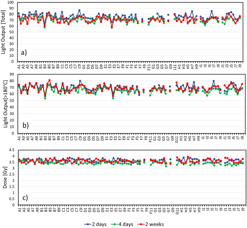
In multiple tests of the encapsulated TLDs, in both in-vivo and ex-vivo irradiation scenarios, results were self consistent, with dose reconstructions falling within 5% between detectors and runs. For example, when 94 TLDs were simultaneously irradiated to 3.4 Gy (e.g. Fig 5, below), the results averaged to 3.6 Gy with a standard deviation of 0.16 Gy (4%).
Figure 5:
Light output from all TLDs used irradiated to 3.6 Gy and read out at various times. a) “Raw” light yield (integral of the PMT readings) b) light yield above 180°C and c) reconstructed Dose.
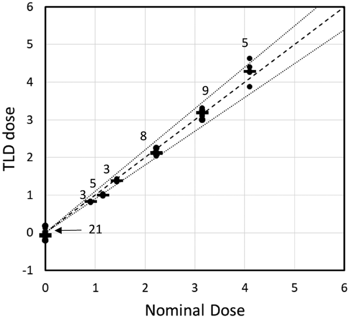
Figure 3 shows results of in-vivo testing of the TLDs. 3-9 mice per dose were irradiated to doses of up to 4.1 Gy at a dose rate of 0.57 Gy/min, as described above. The reconstructed doses reproduce the expected ones within 10%. The standard deviation between TLDs in each grouping was 3-6% of the nominal dose. Dose reconstruction for unirradiated mice was 0.08±0.06 Gy.
Figure 3:
Dose prediction for 33 measurements and 21 controls. The dashed line represents exact match; the dotted line represents ±10%. The number above each cluster of dots is the number of repeats.
Discussion
TLD readout
Even using standard TLD rods, readout requires careful attention to the heating profile. The heating rate is known to influence the observed temperatures of various glow peaks [8] with heating rates above 10°C/min resulting in peaks appearing at higher nominal temperatures.
This temperature lag results from temperature gradients across the heating element, and within the TLD rod and due to improper thermal contact between the heater and TLD [9]. With our encapsulated TLDs, temperature lag effects are expected to be stronger, as the TLD rod is essentially surrounded by an insulator without good thermal contact between the TLD rod and glass or between the glass and heater element.
Corrections for this “temperature lag” have been proposed for heating rates above 10°C/sec (e.g. [10]) and seem to work well [8] but require individual deconvolution of the glow curves. For simplicity we have elected to perform readout at a lower heating rate, minimizing this issue.
We have tested heating profiles, ranging from 1°C/sec to 25°C/sec with and without preheating and did not see significant difference in dose reconstruction between 1 and 10°C/sec. Therefore, for this work we selected a heat rate of 5°C/sec, balancing the slow heating required to minimize temperature lag and increased reproducibility with the requirement to analyse tens of TLD rods at a time, to support mouse irradiations. At this heating rate we were typically able to read out 10 rods in about an hour.
Removing the time dependant glow peak
Figure 4 shows sample glow curves for encapsulated TLD rods, read out at various times post irradiation. A time dependant glow peak is evident at around 160°C. The light yields at higher temperatures however, are independent of time between irradiation and readout.
Figure 4:
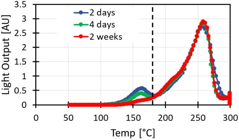
Glow curves for encapsulated TLD-100 irradiated to 3.6 Gy and read at various times post irradiation. Glow curves were integrated right of the dashed line (180°C).
Figure 5, shows the readout for all TLD rods used after irradiation to 3.6 Gy, with varying “hold times” after irradiation. The variability in light yield between individual rods irradiated to the same dose and read together is 7%, whereas the variation between consecutive readouts of the same rod is 4-5% depending on whether the time dependant glow peak is removed or not.
Glass solarization
Similar to the TLD material, ionizing radiation can form free electrons and holes in the glass encapsulation, which may be trapped forming color centers, reducing the transparency of the glass and reducing the overall light yield of the dosimeter. In order to quantify this effect we irradiated 4 mm thick pieces of KG-33 glass using a Co-60 irradiator (dose rate 3.87 Gy/min). We saw a linear increase in optical density (at 450 nm) of about 5.6 10−5 per Gy, reaching a transmission of 50% at 6 kGy. For the 0.2 mm thick encapsulation we use, this would correspond to an absorbtion of ~4% at 6 kGy, which would result in a corresponding 4% reduction in the dose estimate.
However, we have seen that the annealing procedure used for resetting the TLD also completely clears the solarization induced in the encapsulating glass (within a 2% measurment error for transmission; Fig. 6). As the typical doses measured between anneal cycles in our work is in the 0-10 Gy range, we expect no measurable short or long term effect of solarization on the TLD readout.
Figure 6:

“As manufactured” KG-33 glass (left), KG-33 glass irradiated to 6 kGy (center), KG-33 glass irradiated to 6kGy and annealed as described in the text.
Sample tracking.
One of the main problems with TLD chips is that even within a single batch the chip to chip variability is rather poor and, in order to perform reliable dosimetry, each chip needs to be individually calibrated. This raises the need to keep track of individual chips.
Individual calibration of the chips allows us to avoid the need for discarding outlier TLDs. For example TLDs B3 and E5 (see Fig. 5) have a significantly lower response than other TLD rods. However, their individual calibration curves account for this and the dose prediction from these rods did not systematically differ from that of other rods. When all rods were irradiated simultaneously (ex vivo), the variation in dose reconstruction was consistently 4%.
In this work we maintained the TLDs in individually labelled tubes, although this is far from an ideal solution as it requires constant diligence. We are investigating methods for intrinsically labelling the TLDs, but any such method cannot block light and must be able to withstand the 400 °C bake required between irradiations.
Use for dose reconstruction
Accuracy and precision in both dosimetry and irradiation experiments is crucial in studies involving animal models [11]. In most cases this is achieved by proper characterisation of the irradiator however in cases where the irradiations are long and animals are free to move, this is not practical. The encapsulated TLDs we have developed provide a reliable way to account for the animal movement and validate the total delivered dose.
In tests performed using a Gammacell irradiator, the doses delivered to mice reproduced the nominal delivered dose within better than 10%. Table 1 presents an uncertainty budget comparing sources of error : Stochastic errors, variation between TLDs, positioning errors (due to field uniformity in the gammacell irradiator) and uncertainty in the reference chamber used to calibrate tha Gammacell.
Table 1:
Uncertainty budget for TLD based dose reconstruction
Ongoing studies are utilizing these detectors for long term (up to 30 day) irradiations of mice in a low dose rate environemnt. Preliminary results indicate that the actual delivered dose matches the target dose with a similar range.
An issue that was detected in these long studies is the loss of an occasional TLD rod. This was resolved with the application of a small drop of Tissue Adhesive to close the wound after the TLD rod injection.
Conclusions
We presented here a novel encapsulated TLD system for performing in-vivo dosimetry on mice exposed to varying, long term radiation fields. Reconstructed doses were within 10% of the expected dose.
Acknowledgements
The authors would like to acknowledge the support of Eric King and King Precision Glass Inc. (Claremont, CA) in developing the TLD encapsulation procedures.
This work was supported by grant number U19-AI067773 to the Center for High-Throughput Minimally Invasive Radiation Biodosimetry, from the National Institute of Allergy and Infectious Diseases (NIAID), National Institutes of Health (NIH). The content is solely the responsibility of the authors and does not necessarily represent the official views of the NIAID or NIH.
References
- 1.Desrosiers M, et al. , The Importance of Dosimetry Standardization in Radiobiology. Journal of Research of the National Institute of Standards and Technology, 2013. 118: p. 403. [DOI] [PMC free article] [PubMed] [Google Scholar]
- 2.Prado C, et al. , Mean Organ Doses Resulting From Non-Human Primate Whole Thorax Lung Irradiation Prescribed to Mid-Line Tissue. Health physics, 2015. 109(5): p. 367–373. [DOI] [PMC free article] [PubMed] [Google Scholar]
- 3.Garty G, et al. , Mice and the A-Bomb: Irradiation Systems for Realistic Exposure Scenarios. Radiation Research, 2017. 187(4): p. 475–485. [DOI] [PMC free article] [PubMed] [Google Scholar]
- 4.Scarantino CW, et al. , An implantable radiation dosimeter for use in external beam radiation therapy. Medical Physics, 2004. 31(9): p. 2658–2671. [DOI] [PubMed] [Google Scholar]
- 5.Scarantino CW, et al. , The observed variance between predicted and measured radiation dose in breast and prostate patients utilizing an in vivo dosimeter. Int J Radiat Oncol Biol Phys, 2008. 72(2): p. 597–604. [DOI] [PMC free article] [PubMed] [Google Scholar]
- 6.Ismail A, et al. , Radiotherapy quality assurance by individualized in vivo dosimetry: state of the art. Cancer Radiother, 2009. 13(3): p. 182–9. [DOI] [PubMed] [Google Scholar]
- 7.Cai G, Wang S, and Zhang J, Radiation damage and recovery of LiF:Mg, Ti-TLD at the dose of 106 Gy γ-rays. 1990. 121(1): p. 57–61. [Google Scholar]
- 8.Singh R and Kainth HS, Effect of heating rate on thermoluminescence output of LiF: Mg, Ti (TLD-100) in dosimetric applications. Nuclear Instruments and Methods in Physics Research Section B: Beam Interactions with Materials and Atoms, 2018. 426: p. 22–29. [Google Scholar]
- 9.Taylor GC and Lilley E, Rapid readout rate of studies of thermoluminescence in LiF (TLD-100) crystals. III. Journal of Physics D: Applied Physics, 1982. 15(10): p. 2053–2065. [Google Scholar]
- 10.Kitis G and Tuyn JWN, A simple method to correct for the temperature lag in TL glow-curve measurements. Journal of Physics D: Applied Physics, 1998. 31(16): p. 2065–2073. [Google Scholar]
- 11.US Food and Drug Administration, Radiation Biodosimetry Devices: Draft Guidance for Industry and Food and Drug Administration Staff, C.f.D.a.R. Health, Editor. 2014. [Google Scholar]


