Abstract
We propose a model to generate electrocardiogram signals based on a discretized reaction-diffusion system to produce a set of three nonlinear oscillators that simulate the main pacemakers in the heart. The model reproduces electrocardiograms from healthy hearts and from patients suffering various well-known rhythm disorders. In particular, it is shown that under ventricular fibrillation, the electrocardiogram signal is chaotic and the transition from sinus rhythm to chaos is consistent with the Ruelle-Takens-Newhouse route to chaos, as experimental studies indicate. The proposed model constitutes a useful tool for research, medical education, and clinical testing purposes. An electronic device based on the model was built for these purposes
Subject terms: Applied mathematics, Software
Introduction
The human heart beats for about 2 to 3 billion times in a normal life. The heart pumping function is initiated by action potentials arising from the sinoatrial (SA) node. This electrical signal travels through the atrial muscles to the atrioventricular (AV) node. Finally, the electrical impulses propagate along the His-Purkinje complex causing the contraction of the ventricular muscles. This process leads to the blood supply into the whole body1. The depolarization and repolarization events occurring with each cardiac cycle reflects the ionic current flow which gives place to a time-varying electrical potential on the surface of the skin, which represents the physical information recorded in an electrocardiogram (ECG). Since the ECG signal contains information of the electrical events of cardiac cycle, it has been widely used for detecting abnormalities of the heart, usually called arrhythmias1,2. Among these is the particularly malignant ventricular fibrillation (VF) which without timely medical intervention causes the sudden cardiac death in a few minutes3. Since the VF is distinguished by a state of irregular arrhythmic contraction of the ventricular muscles, it has been signaled as a stochastic and erratic process. However, nonlinear dynamical systems theory is recognized as a useful tool that can contribute to the understanding of underlying mechanisms of lethal arrhythmias and cardiac diseases4.
Heart functioning can be modeled with different levels of detail. Some models describe the function of the heart at cell level5,6. Others include spatiotemporal characteristics of the heart rhythms7,8. There are also models based on ECG signals that describe the electrical activity of the heart at a macroscopic level9,10. In this realm, a relatively old idea is to consider the heart as a network of relaxation oscillators, following the pioneering studies developed by Van der Pol and Van der Mark (VdP)11. Since the work of VdP several modifications have been proposed to model the electrical activity in the heart because the VdP oscillator displays many features occurring in the biological context12. All models that reproduce the electrical activity of the heart using coupled nonlinear oscillators are complex and based on modified VdP coupled oscillators. Furthermore, the couplings usually include time delays, which can cause drastic changes in the system dynamics, and even the emergence of deterministic chaos13. Several studies about the effect of conduction delays in coupled oscillators have been reported14. The classical way to model the electrical activity of the heart is by using reaction-diffusion (RD) equations (see for example, refs. 15,16), because the propagation of electrical waves through the heart is similar to the propagation of nonlinear waves. In other systems, we could say that models based on VdP nonlinear oscillators are somewhat simplified and do not capture all the features one wants to model.
Experimental studies based on the analysis of electrocardiogram recordings of dog hearts17–19, which were electrically induced to a VF, suggest the presence of chaos, resulting from nonlinear deterministic dynamics20. Even more, in ref. 21. the fibrillation was studied in three stable biological models: chronic human atrial fibrillation, stabilized canine ventricular fibrillation and fibrillation like activity in thin sheets of canine and human ventricular tissue in vitro. By analyzing the experimental data recorded, the results indicate that fibrillation is an example of spatio-temporal chaos arising from a sinus rhythm following the Ruelle-Takens-Newhouse route to chaos22. In a previous paper23, we proposed an extension of the model developed in24 (which reproduces clinically comparable ECG waveforms) to produce chaotic responses associated with VF by the inclusion of an ectopic pacemaker (EP) that stimulates the ventricular muscles. The idea that the VF presents chaotic behavior may suggest new therapeutic strategies to avoid it.
In this work we propose a mathematical model based on a reaction-diffusion mechanism25 to simulate the generation of ECG signals.The model is discretized in a way that a set of three coupled nonlinear oscillators (not VdP type) is obtained and used to describe the electrical activity of the heart. The three nonlinear oscillators can be assigned to the natural pacemakers in the heart, and the ECG signals can be simulated as a combined signal of the variables of these oscillators. Although the present work and previous study23 were born from different inspirations, they maintain three common aspects: (1) are based on coupled nonlinear oscillators (the natural pacemakers in the heart are described by three coupled oscillators); (2) follow the same route to chaos; and (3) are capable to reproduce electrocardiogram signals of healthy hearts as well as some arrhythmias.
Methods
The model
Reaction-diffusion equations have been used to model the electrical activity of the heart26,27. Electric activation propagating along nerve fibers arise from the flow of ions across the cell membrane (ionic currents), that is, from the movement of ions inside or outside of the extracellular space28. These ionic currents are represented in the reaction kinetics added the diffusion equation for the membrane potential.
The Barrio-Varea-Aragon-Maini (BVAM) model25 is a generic reaction-diffusion system obtained by assuming mass conservation of two morphogens and by a Taylor expansion around an equilibrium point, retaining up to cubic non-linearities. This model has been used for describing a wide diversity of patterns present in biological or chemical systems29,30. The BVAM model exhibits extremely rich dynamics, ranging from Turing patterns, traveling waves, temporal oscillations and chaotic behavior31. In dimensionless form, the BVAM model is:
| 1a |
| 1b |
where u(x, t) and v(x, t) describe two interacting variables at position x and time t with constant diffusion coefficient ratio D. These variables could be interpreted as chemical substances, morphogens or any other measurable quantity, depending on the particular system to be modeled. Here, η, a, b, C and H are parameters of the system. Zero flux (Newmann) boundary conditions are usually used. From a mathematical point of view, this election is justified due to the interest in self-organized patters and zero flux imply no external input. From a physiological point of view, zero flux imply electrical insulating boundaries.
As in31, we consider parameter values: η = 1, a = −1 and b = −3. These values situate the model in a region where it produces nonlinear oscillations in an excitable medium, and complies with the basic requirements to model the cardiac beat.
Upon applying the simple Euler description to a discrete Laplacian, we recast Eq. (1) as a system of ordinary differential equations (ODE). In doing so, we associate the resulting system of differential equations to the natural pacemakers in the heart by taking into account a three-node standard stencil of the domain of length L. In this way, two nodes correspond to the boundaries x = 0, x = L and another one within the domain. As zero-flux boundary conditions are into consideration, i.e. ux = vx = 0 at x = 0, L, first derivatives are approximated by forward and backward differences. From this, we obtain u4 = u3, v4 = v3, u0 = u1 and v0 = v1. Upon defining x1 = u1, x2 = v1, x3 = u2, x4 = v2, x5 = u3 and x6 = v3, we obtain a six-component ODE system:
| 2 |
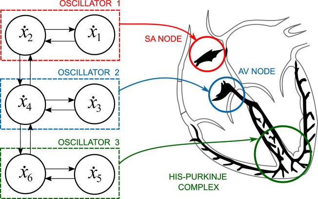
where β = 1/(Δx)2 is the coupling constant in the discrete Laplacian. These three identical oscillators, coupled in series, could be interpreted as the three natural pacemakers of the heart, namely, the SA node, the AV node and the His-Purkinje complex1, as depicted in Fig. 1. Note that the system represents each pacemaker with similar oscillators and that they are coupled in series.
Figure 1.
Diagram relating the cardiac natural pacemakers to the nonlinear variables x1 − x6 of the discretized BVAM model (2). Here, the action potentials of the SA node, AV node, and His-Purkinje complex are represented by coupled three oscillators, respectively.
From the numerical integration of system (2), we note that the variables x1, x5, and x2, x6, respectively, are not independent to each other due to symmetry. Thus, a further reduction of the system (2) can be made. The resulting equivalent system of equations are simultaneously satisfied as x2 = x6, which yields that x1 = x5. Finally, system (2) is reduced to the four-component ODE system:
| 3 |
Since the ECG signal is a composition of waves coming from different areas of the heart with different magnitudes, it can be considered, as a first approximation, that the ECG signal is a linear mixing of the electrical activations of the main cardiac pacemakers with different strengths32. In this way, signals that closely resemble ECG signals can be generated by an adequate linear combination of the variables xi:
| 4 |
Results
Ventricular fibrillation
As it was already mentioned, experimental studies21 suggest that ventricular fibrillation is a form of spatio-temporal chaos that arises from a normal rhythm through the so-called Ruelle-Takens-Newhouse scenario22. In what follows we will show that system (3) can exhibit this behaviour under the variation of the control parameter H.
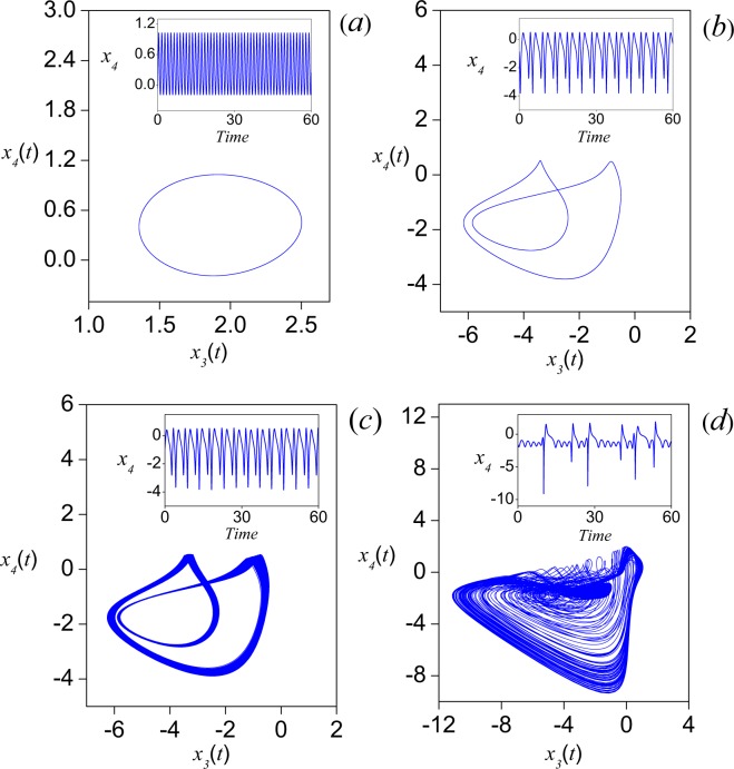
Since the analytical treatment of nonlinear terms is often prohibitive, five numerically calculated quantities are used to analyze the system, namely, time series, phase portrait, power spectrum, bifurcation diagram and largest Lyapunov exponent. First of all, we observe that H governs the linear terms, while C is the ratio of the strengths of quadratic and cubic nonlinearity. By making a linear analysis of the model (1), without the diffusion term (resulting equations have the same form that the equations of individual oscillators in the system (3)), the equilibrium point (0, 0) presents stationary solutions for . In order to keep the behavior simple, we have fixed C = 1.35 and define H as the control parameter, in the interval [1, 20]. System (3) was solved numerically using the step-fixed Runge-Kutta method33 with Δt = 0.00534,35. To boot up system (3), a perturbed state around the equilibrium point (0, 0, 0, 0) can be obtained by disturbing any of the dynamical variables. We consider the case x(0) = (0, 0, 0.1, 0) as one of the possible alternatives to stimulate the system. It is worth mentioning that all simulations in this work were carried out by using the same numerical method, integration step and initial conditions, as well as the parameter values C = 1.35 and β = 4. In Fig. 2, the phase portraits for x4 versus x3 are shown for different values of H. As depicted in Fig. 2(a), for H = 7 a limit cycle is formed. For H = 2.74, the limit cycle doubles its period (Fig. 2(b)) and for H = 2.72972, a torus is generated (Fig. 2(c)), which corresponds to a quasi-periodic oscillation where at least two incommensurate frequencies are involved (see the inset). When H = 2.7126 (Fig. 2(d)) a strange attractor seems to be formed, thus a completely irregular time series can be observed (inset).
Figure 2.
Phase portraits for four different values of the control parameter H, after t = 500 seconds. (a) H = 7, (b) H = 2.74, (c) H = 2.72972, and (d) H = 2.7126. In the insets, the corresponding time series (in seconds) for the x4 variable are shown. Numerical simulations were carried out with C = 1.35 and β = 4.
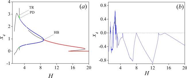
To confirm the results suggested by the time series and the phase portraits (see also the power spectra shown in Fig. 4 below), we have numerically computed the bifurcation diagram using the software AUTO36, by varying the control parameter in the interval 1 ≤ H ≤ 20. The bifurcation diagram is shown in Fig. 3(a), where one could notice that steady-states undergo transitions from stationary to Hopf to Period Doubling to Two Torus to Three Torus (namely Chaos). As it seen in Fig. 3(a) all the interesting bifurcations occur in the interval [1, 9]. However, we decided to keep the results up to H = 20, to show the rich variety of dynamics of the system.
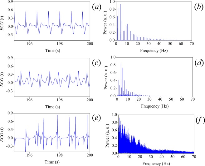
Figure 4.
ECG’s corresponding to: (a) normal rhythm (H = 3), (c) quasiperiodicity (H = 2.729) and (e) VF (H = 2.164). Their corresponding power spectra, (b), (d) and (f), are shown on the right of each ECG plot, respectively.
Figure 3.
Numerically calculated bifurcation diagram of model (3) using AUTO. (a) Supercritical Hopf (HB), period doubling (PD), and torus (TR) bifurcations are detected at H = 8.779267, 2.742524 and 2.72972, respectively. Here, red line corresponds to a family of stationary states and blue line to a set of stable limit cycles. Periodic solutions with half the frequency are indicated by the green line. Finally, the loss of stability in the period doubling gives place to the quasi-periodicity (black line). Small perturbations transform the quasiperiodic orbits into a chaotic motion. (b) Largest Lyapunov exponents as H is varied.
A family of stationary states is found for values of H ≥ 9. As H is decreased, a branch consisting of stable limit cycles arises from a supercritical Hopf bifurcation (HB) point at H = 8.779267. This branch loses stability as a Period Doubling (PD) point is attained at H = 2.742524. Finally, this branch undergoes a transition through a Torus point (TR) at H = 2.72972. Notice that these features are shown in Fig. 2, where the initial limit cycle is continuously shifted forming a torus, which gives place to quasi-periodicity. Finally, small perturbations transform the quasiperiodic orbit into a chaotic motion, or a strange attractor. All these results are consistent with the Ruelle-Takens-Newhouse route to chaos22,37. To confirm the existence of chaos, the largest Lyapunov exponents (λ) were numerically computed. Figure 3(b) shows the largest Lyapunov exponent as function of H, using an incremental step of 0.009 for H. Observe positive values in the region of chaos.
Since the model in Eq. (3) is written in non-dimensional form, we need to add a scale factor to obtain ECG signals with the correct oscillations in time. If a factor Γt multiplies the right hand side of (3), i.e., , then Γt follows a linear dependence on the heart rate (in beats per minute), given by the following expression:
| 5 |
where HRbpm is the heart rate. To obtain above equation, the dependence of the scaling factor Γt with the heart rate was found by numerically integrating system (3), taking a normal ECG waveform as reference. Given this dependence, we fit it with a monomial function.
In Fig. 4 we show ECG’s corresponding to (a) normal rhythm (H = 3), (c) quasiperiodicity (H = 2.729) and (e) VF (H = 2.164), with their corresponding power spectra in the right hand side. For all rhythms in this subsection, the numerical simulations of (4) were carried out with C = 1.35, β = 4, and scaling coefficients: α1 = −0.024, α2 = 0.0216, α3 = −0.0012, and α4 = 0.12. αi coefficients were calculated using a modification of the supervised learning algorithm called perceptron38,39. The time scaling factors, Γt = 7, for normal and period doubling rhythms, and Γt = 17 for VF were computed using (5), in order to recover the physiological times.
Some words concerning the role of the model parameters are in order: coefficients αi correspond to the contribution of each compartment xi (related to nodes). β captures the coupling between nodes, considering that it is a dynamical network. H and C control the compartment-to-compartment local interaction of the dynamical network. Finally, the time-scale parameter Γt can be justified in the same way as the parameter Cm used to correct the time scale of the action potential in the Purkinje fibers in Noble’s model40 and the parameters χ and Cm in Sundnes et al.41 (Sundnes’ model).
Numerical simulations
Using (4) the ECG signal corresponding to the normal sinus rhythm is obtained with the following parameter values: α1 = −0.024, α2 = 0.0216, α3 = −0.0012, α4 = 0.12 and Γt = 7. In Fig. 5 the ECG signal (standard Einthoven lead II) and the xi variables, obtained by numerical simulation of Eqs. (4) and (3), are shown. In the figure we also show the simulated ECG (c) to be compared with an ECG signal obtained from ref. 42 (shown in (b)). Our model reproduces only lead II, which forms part of the main leads in Einthoven’s triangle and is commonly used by cardiologists to provide a rhythm strip43.
Figure 5.
Time series: (a) The xi variables of (3): i = 1 (blue line), i = 2 (green line), i = 3 (gray line) and i = 4 (red line). (b) Real ECG42. (c) ECG signal obtained from (4).
The time evolution of the state variables in (3) is shown in Fig. 5(a). Notice that x4 alone generates a signal closely related to the ECG waveform. This is because x4 contains the dynamics of the HP complex and the AV node combined, as a result of the reduction from the system of Eqs. (2) to (3), that is, from three to two oscillators. However, we have proposed the linear combination (4) in order to obtain a better approximation, as it is shown in Fig. 5(c), from where we observe that the model captures the most important characteristics of a real ECG. Notice also that the only coupling of the oscillators is through parameter β, which plays a crucial role on modifying the output waveform.
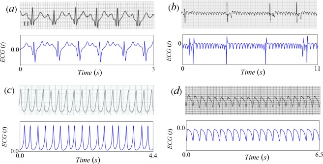
The parameter space was explored to reproduce the most important pathological arrythmias (see Table 1). Here, parameter H was selected from the bifurcation diagram and αi coefficients in Table 1 were calculated using the modified perceptron algorithm like in the above subsection. Our results are exhibited in Fig. 6, where they are compared with ECG (standard Einthoven lead II) obtained from42,44–46.
Table 1.
Parameters for arrhythmias. In all cases C = 1.35 and H = 2.848.
| Pathology | Parameters |
|---|---|
| Sinus Tachycardia |
H = 2.848, α1 = 0, α2 = −0.1, α3 = 0 α4 = 0 and Γt = 21. |
| Atrial Flutter |
H = 1.52, α1 = −0.068, α2 = 0.028, α3 = −0.024, α4 = 0.12 and Γt = 13 |
| Ventricular Tachycardia |
H = 2.178, α1 = 0, α2 = 0, α3 = 0 α4 = −0.1 and Γt = 21 |
| Ventricular Flutter |
H = 2.178, α1 = 0.1, α2 = −0.02, α3 = −0.01, α4 = 0 and Γt = 13. |
Figure 6.
Comparison of ECG plots obtained from experimental observations (top panels) and the reduced system (3) (bottom panels). (a) Sinus tachycardia44, (b) Atrial flutter42, (c) Ventricular tachycardia45 and (d) Ventricular flutter46.
In sinus tachycardia (Fig. 6(a)) an exaggerated acceleration of heart rate greater than 100 bpm occurs. In Fig. 6(b) an atrial flutter can be observed. Ventricular tachycardia (VT) is a fast rhythm that begins in the ventricles. It is characterized by a pulse greater than 100 bpm (see Fig. 6(c)). Finally, in Fig. 6(d), we show a ventricular flutter, which is characterized by a very rapid (150 up to 250 bpm) and regular ectopic ventricular rhythm. It is usually preceded by VT and this condition is fatal if untreated. Notice the striking similarities between the theoretical results and all pathological ECG. An important feature of our model is that it is capable to reproduce several well-known rhythm disorders with a relatively good matching of the shapes and amplitudes of realistic ECGs.
Electronic implementation
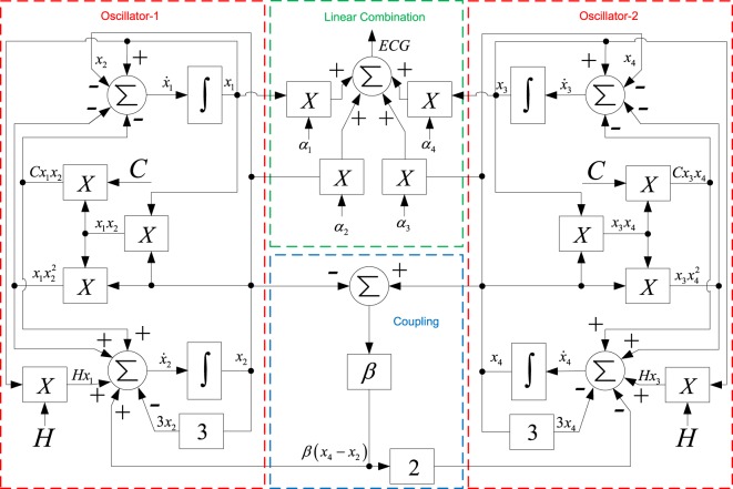
The system (3) can be electronically implemented by using analog multipliers and inverting configurations of operational amplifiers (OPAMPs), such as the adder, integrator, and gain. In other words, we use the working principle of an analog computer to represent physical variables of the mathematical model through input and output voltage variables of an analog electronic circuit. In this way, in order to simulate any mathematical model in an analog computer, the sequence of mathematical operations involved in the process must be described by means of functional block diagrams. Figure 7 shows the block diagram of the system (3) and the linear combination in (4) to obtain the ECG signal.
Figure 7.
Block diagram of the system (3) and the linear combination (4).
Each mathematical operation involved in the block diagram can be electronically implemented with linear and nonlinear electronic components. Note that the block diagram obtained for x1 and x2 (named Oscillator-1) is equal as that obtained with x3 and x4 (named Oscillator-2). Therefore, both oscillators can be implemented with identical electronic circuits.
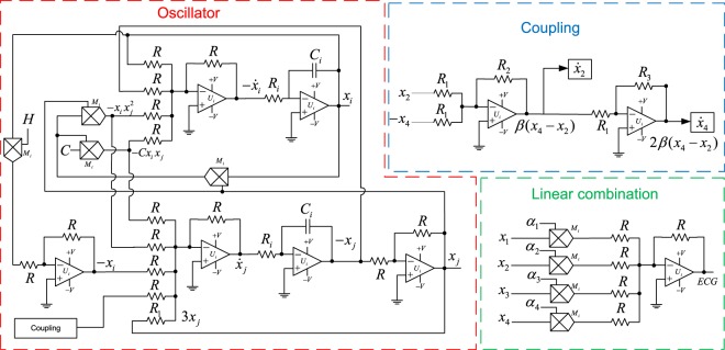
Figure 8 shows the synthesized analog circuit for an oscillator, the coupling and the linear combination (4). Since inverting configurations of OPAMPs are used, an inherent sign inversion must be taken into account in the design. Ri, Ci, Ui and Mi stand for resistors, capacitors, general purpose operational amplifier and analog multipliers, respectively. The values of R, R1, R2, R3, Ri, Ci are defined by the parameters of the system. They must satisfy:
| 6 |
Figure 8.
Proposed analog electronic circuit.
We calculated the resistors and capacitors involved in Fig. 8, considering Γt = 7 and β = 4. By selecting R = 3 KΩ, R1 = 1 KΩ, R2 = 4 KΩ, R3 = 2 KΩ, Ri = 14 kΩ, Ci = 10 μF, the conditions given by (6) are satisfied. Ui and Mi correspond to OPAMPs and analog multipliers of the series MC1458 and AD633, respectively.
An important feature of the proposed electronic implementation is that the parameters H, C and αi are introduced in the circuit via a voltage signal. This is particularly relevant because the value of each parameter can be defined independently from the circuit, this implies that in order to set the desired parameter value it is not required to physically change some electronic components (resistors or capacitors).
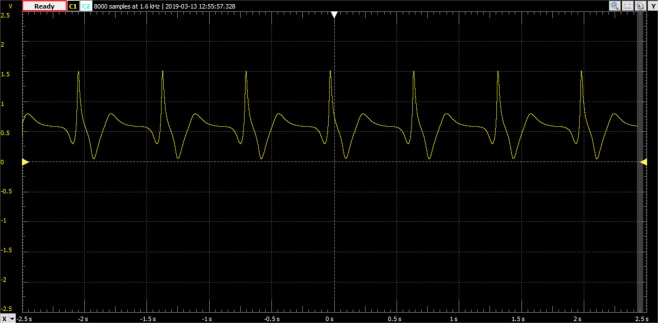
As an example, in Fig. 9, the output of the proposed analog electronic circuits is shown for the normal sinus rhythm, for the same parameter values used in Fig. 5(c).
Figure 9.
Oscilloscope output of the proposed analog electronic circuits for the normal sinus rhythm.
Discussion
In this work a model to generate electrocardiogram signals by means of coupled nonlinear oscillators was proposed. By defining a linear combination of the contributions of the oscillator variables involved, healthy ECG signals are obtained, as well as realistic ECG’s presenting several crucial arrhythmias.
An important feature of our model is that the transition from normal rhythm to VF is controlled by a single parameter, contrary to other models where several parameters should be varied or an external oscillator or signal must be included to reproduce chaotic behaviours associated with VF23,32. Here, the control parameter H plays a boosting role from variable u to v; this role can also be seen in the reduced system (3).
We considered the case of ventricular fibrillation in more detail. With the aid of numerical tools, we conclude that in our model, the ECG of this dangerous arrhythmia is a chaotic signal and that the transition from sinus rhythm to VF, when varying a control parameter, follows the Ruelle-Takens-Newhouse route to chaos.
Finally, as the proposed model constitutes a useful tool for medical education, research and testing purposes, an electronic implementation of the model was proposed and built. Observe that an experimented physician could object that our theoretical ECG’s do not exactly resemble the real ones from everyday patients. This points out to the limitations of any modeling, which necessarily represents a simplification of the real world. Nevertheless, our model captures the main features of the normal and abnormal recordings and opens new ways to the understanding of the origins of the most usual heart failures.
Acknowledgements
J.L.A., R.V.M., O.J.R., M.A.Q.J. and R.A.B. were supported by UNAM-PAPIIT and CONACYT through grants IN110817 and A1-S-8317, respectively. In addition, M.A.Q.J. acknowledges postdoctoral financial support from CONACyT through grants ICN-UNAM-284372. R.V.M. and O.J.R. thank financial support from IPN-México, through grant SIP-IPN-20181398 and SIP-IPN-20182124, respectively. Finally, R.A.B. is grateful to PASPA, DGAPA, UNAM for a sabbatical grant and acknowledges financial support from CONACyT project 283279.
Author contributions
J.L.A. and R.A.B. devised the project and the main conceptual ideas. J.L.A., R.A.B., V.B.M. and M.A.Q.J. developed the theory. M.A.Q.J., R.V.M. and O.J.R. performed the computations, designed and built the electronic implementation. All authors discussed the results and contributed to the final manuscript.
Competing interests
The authors declare no competing interests.
Footnotes
Publisher’s note Springer Nature remains neutral with regard to jurisdictional claims in published maps and institutional affiliations.
References
- 1.Keener, J. P. & Sneyd, J. Mathematical Physiology II: Systems Physiology, vol. 8 of Interdisciplinary Applied Mathematics, second edn. (Springer-Verlag, New York, 2008).
- 2.da S. Luz EJ, Schwartz WR, Cámara-Chávez G, Menotti D. Ecg-based heartbeat classification for arrhythmia detection: A survey. Comp. Meth. Prog. Bio. 2016;127:144–164. doi: 10.1016/j.cmpb.2015.12.008. [DOI] [PubMed] [Google Scholar]
- 3.Gray RA, Pertsov AM, Jalife J. Spatial and temporal organization during cardiac fibrillation. Nat. 1998;392:75–78. doi: 10.1038/32164. [DOI] [PubMed] [Google Scholar]
- 4.Qu Z, Hu G, Garfinkel A, Weiss JN. Nonlinear and stochastic dynamics in the heart. Phys. Rep. 2014;543:61–162. doi: 10.1016/j.physrep.2014.05.002. [DOI] [PMC free article] [PubMed] [Google Scholar]
- 5.Hoffman BF, Rosen MR. Cellular mechanisms for cardiac arrhythmias. Circ. Res. 1981;49:1–15. doi: 10.1161/01.RES.49.1.1. [DOI] [PubMed] [Google Scholar]
- 6.Echebarria B, Karma A. Mechanisms for initiation of cardiac discordant alternans. Eur. Phys. J. ST. 2007;146:217–231. doi: 10.1140/epjst/e2007-00182-y. [DOI] [Google Scholar]
- 7.Ten Tusscher K, Panfilov A. Modelling of the ventricular conduction system. Prog. Biophys. Mol. Biol. 2008;96:152–170. doi: 10.1016/j.pbiomolbio.2007.07.026. [DOI] [PubMed] [Google Scholar]
- 8.Christensen K, Manani KA, Peters NS. Simple model for identifying critical regions in atrial fibrillation. Phys. Rev. Lett. 2015;114:028104. doi: 10.1103/PhysRevLett.114.028104. [DOI] [PMC free article] [PubMed] [Google Scholar]
- 9.McSharry PE, Clifford GD, Tarassenko L, Smith LA. A dynamical model for generating synthetic electrocardiogram signals. IEEE T. Bio.-Med. Eng- 2003;50:289–294. doi: 10.1109/TBME.2003.808805. [DOI] [PubMed] [Google Scholar]
- 10.Gidea M, Gidea C, Byrd W. Deterministic models for simulating electrocardiographic signals. Commun. Nonlinear Sci. 2011;16:3871–3880. doi: 10.1016/j.cnsns.2011.01.022. [DOI] [Google Scholar]
- 11.Van der Pol B, Van der Mark J. Lxxii. the heartbeat considered as a relaxation oscillation, and an electrical model of the heart. The London, Edinburgh, Dublin Philos. Mag. J. Sci. 1928;6:763–775. doi: 10.1080/14786441108564652. [DOI] [Google Scholar]
- 12.Glass, L., Hunter, P. & McCulloch, A. Theory of heart: biomechanics, biophysics, and nonlinear dynamics of cardiac function (Springer-Verlag, New York, 1991).
- 13.Sprott J. A simple chaotic delay differential equation. Phys. Lett. A. 2007;366:397–402. doi: 10.1016/j.physleta.2007.01.083. [DOI] [Google Scholar]
- 14.dos Santos AM, Lopes SR, Viana RRL. Rhythm synchronization and chaotic modulation of coupled van der pol oscillators in a model for the heartbeat. Phys. A. 2004;338:335–355. doi: 10.1016/j.physa.2004.02.058. [DOI] [Google Scholar]
- 15.Gray RA, Jalife J. Ventricular fibrillation and atrial fibrillation are two different beasts. Chaos. 1998;8:65–78. doi: 10.1063/1.166288. [DOI] [PubMed] [Google Scholar]
- 16.Keldermann RH, Nash MP, Panfilov AV. Modeling cardiac mechano-electrical feedback using reaction-diffusion mechanics. Phys. D. 2009;238:1000–1007. doi: 10.1016/j.physd.2008.08.017. [DOI] [Google Scholar]
- 17.Witkowski FX, et al. Spatiotemporal evolution of ventricular fibrillation. Nat. 1998;392:78–82. doi: 10.1038/32170. [DOI] [PubMed] [Google Scholar]
- 18.Kaplan DT, Cohen RJ. Is fibrillation chaos? Circ. Res. 1990;67:886–892. doi: 10.1161/01.RES.67.4.886. [DOI] [PubMed] [Google Scholar]
- 19.Witkowski FX, et al. Evidence for determinism in ventricular fibrillation. Phys. Rev. Lett. 1995;75:1230. doi: 10.1103/PhysRevLett.75.1230. [DOI] [PubMed] [Google Scholar]
- 20.Zhao Y, Sun J, Small M. Evidence consistent with deterministic chaos in human cardiac data: surrogate and nonlinear dynamical modeling. Int. J. Bifurcat. Chaos. 2008;18:141–160. doi: 10.1142/S0218127408020197. [DOI] [Google Scholar]
- 21.Garfinkel A, et al. Quasiperiodicity and chaos in cardiac fibrillation. J. Clin. Invest. 1997;99:305. doi: 10.1172/JCI119159. [DOI] [PMC free article] [PubMed] [Google Scholar]
- 22.Newhouse S, Ruelle D, Takens F. Occurrence of strange axiom a attractors near quasi periodic flows on tm, m ≥ 3. Comm. Math. Phys. 1978;64:35–40. doi: 10.1007/BF01940759. [DOI] [Google Scholar]
- 23.Quiroz-Juárez M, Vázquez-Medina R, Ryzhii E, Ryzhii M, Aragón J. Quasiperiodicity route to chaos in cardiac conduction model. Commun. Nonlinear Sci. 2017;42:370–378. doi: 10.1016/j.cnsns.2016.06.007. [DOI] [Google Scholar]
- 24.Ryzhii E, Ryzhii M. A heterogeneous coupled oscillator model for simulation of ecg signals. Comp. Meth. Prog. Bio. 2014;117:40–49. doi: 10.1016/j.cmpb.2014.04.009. [DOI] [PubMed] [Google Scholar]
- 25.Barrio R, Varea C, Aragón J, Maini P. A two-dimensional numerical study of spatial pattern formation in interacting turing systems. Bull. Math. Biol. 1999;61:483–505. doi: 10.1006/bulm.1998.0093. [DOI] [PubMed] [Google Scholar]
- 26.Berenfeld O, Abboud S. Simulation of cardiac activity and the ecg using a heart model with a reaction-diffusion action potential. Med. Eng. Phys. 1996;18:615–625. doi: 10.1016/S1350-4533(96)00028-8. [DOI] [PubMed] [Google Scholar]
- 27.Potse M, Dubé B, Richer J, Vinet A. A comparison of monodomain and bidomain reaction-diffusion models for action potential propagation in the human heart. IEEE T. Bio-Med. Eng. 2005;197:35–66. doi: 10.1109/TBME.2006.880875. [DOI] [PubMed] [Google Scholar]
- 28.Malmivuo, P., Malmivuo, J. & Plonsey, R. Bioelectromagnetism: principles and applications of bioelectric and biomagnetic fields, (Oxford University Press, USA, 1995).
- 29.Toole G, Hurdal MK. Growth in a turing model of cortical folding. Biomath. 2012;1:1–7. doi: 10.11145/j.biomath.2012.09.252. [DOI] [Google Scholar]
- 30.Woolley TE, Baker RE, Maini PK, Aragón JL, Barrio RA. Analysis of stationary droplets in a generic turing reaction-diffusion system. Phys. Rev. E. 2010;82:051929. doi: 10.1103/PhysRevE.82.051929. [DOI] [PubMed] [Google Scholar]
- 31.Aragón J, Barrio R, Woolley T, Baker R, Maini P. Nonlinear effects on turing patterns: Time oscillations and chaos. Phys. Rev. E. 2012;86:026201. doi: 10.1103/PhysRevE.86.026201. [DOI] [PubMed] [Google Scholar]
- 32.Gois SR, Savi MA. An analysis of heart rhythm dynamics using a three-coupled oscillator model. Chaos Soliton. Fract. 2009;41:2553–2565. doi: 10.1016/j.chaos.2008.09.040. [DOI] [Google Scholar]
- 33.Butcher, J. C. Numerical methods for ordinary differential equations, third edn. (John Wiley & Sons, 2016).
- 34.Lotkin M. On the accuracy of Runge-Kutta’s method. Math. T&OAC Am. Math. Soc. 1951;5:128–133. doi: 10.1090/S0025-5718-1951-0043566-3. [DOI] [Google Scholar]
- 35.Shampine, L. F. Numerical solution of ordinary differential equations (Taylor & Francis Group, 2018).
- 36.Ermentrout, B. Simulating, analyzing, and animating dynamical systems: a guide to XPPAUT for researchers and students, vol. 14 (Society for Industrial and Applied Mathematics, 2002).
- 37.Eckmann J-P. Roads to turbulence in dissipative dynamical systems. Rev. Mod. Phys. 1981;53:643. doi: 10.1103/RevModPhys.53.643. [DOI] [Google Scholar]
- 38.Quiroz-Juárez M, et al. Cardiac conduction model for generating 12 lead ecg signals with realistic heart rate dynamics. IEEE Transactions on NanoBioscience. 2018;17:525–532. doi: 10.1109/TNB.2018.2870331. [DOI] [PubMed] [Google Scholar]
- 39.Quiroz-Juárez M, Jiménez-Ramírez O, Aragón J, Del Río-Correa J, Vázquez-Medina R. Periodically kicked network of rlc oscillators to produce ecg signals. Comput. Biol. Medicine. 2019;104:87–96. doi: 10.1016/j.compbiomed.2018.05.017. [DOI] [PubMed] [Google Scholar]
- 40.Noble D. A modification of the hodgkin—huxley equations applicable to purkinje fibre action and pacemaker potentials. J. Physiol. 1962;160:317–352. doi: 10.1113/jphysiol.1962.sp006849. [DOI] [PMC free article] [PubMed] [Google Scholar]
- 41.Sundnes, J. et al. Computing the electrical activity in the heart. (Springer, Berlin, 1986).
- 42.Jenkins, D. & Gerred, S. ECG libraryhttp://www.ecglibrary.com (2017).
- 43.Meek S, Morris F. ABC of clinical electrocardiography. Introduction. I—leads, rate, rhythm, and cardiac axis. Clin. research. 2002;324:415–418. doi: 10.1136/bmj.324.7334.415. [DOI] [PMC free article] [PubMed] [Google Scholar]
- 44.Yanowitz, F. G. ECG Learning Centerhttp://ecg.utah.edu. (2017).
- 45.de Jong, J. Ecgpediahttp://en.ecgpedia.org (2017).
- 46.Burns, E. ECG libraryhttp://lifeinthefastlane.com/ecg-library/ (2017).


