Significance
The virus bacteriophage T4 infects the bacterium Escherichia coli using an intriguing nanoscale injection machinery that employs a contractile tail. The injection machinery is responsible for recognizing and puncturing the bacterial host and transferring the viral genome into the host during infection. Fundamental questions remain concerning how this injection process unfolds in real time, a process that presently defies direct experimental observation. Using a combination of atomistic and continuum representations, this study contributes a system-level model of the entire bacteriophage T4 interacting with a host cell, and in doing so, it exposes the energetics, forces, and dynamical pathway associated with the injection process. The results have further implications for future nanotechnology devices for DNA transfection and experimental phage therapies.
Keywords: bacteriophage T4, injection machinery, sheath contraction, dynamical pathway
Abstract
The virus bacteriophage T4, from the family Myoviridae, employs an intriguing contractile injection machine to inject its genome into the bacterium Escherichia coli. Although the atomic structure of phage T4 is largely understood, the dynamics of its injection machinery remains unknown. This study contributes a system-level model describing the nonlinear dynamics of the phage T4 injection machinery interacting with a host cell. The model employs a continuum representation of the contractile sheath using elastic constants inferred from atomistic molecular-dynamics (MD) simulations. Importantly, the sheath model is coupled to component models representing the remaining structures of the virus and the host cell. The resulting system-level model captures virus–cell interactions as well as competing energetic mechanisms that release and dissipate energy during the injection process. Simulations reveal the dynamical pathway of the injection process as a “contraction wave” that propagates along the sheath, the energy that powers the injection machinery, the forces responsible for piercing the host cell membrane, and the energy dissipation that controls the timescale of the injection process. These results from the model compare favorably with the available (but limited) experimental measurements.
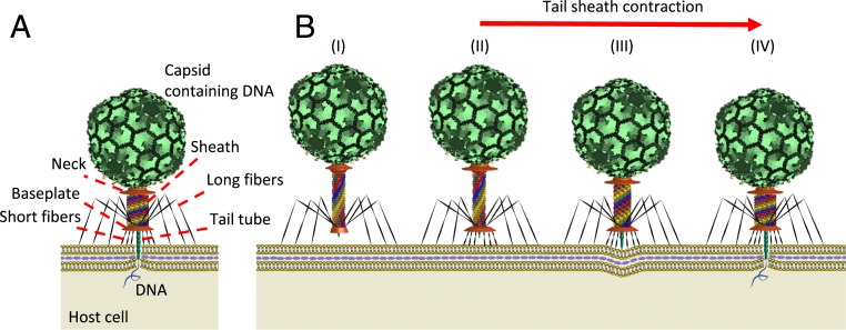
Bacteriophage T4 from family Myoviridae is one of the most complex tailed viruses that infects Escherichia coli (E. coli) by injecting its genome into the host cell using a highly efficient contractile injection machinery. As illustrated in Fig. 1A, phage T4 possesses a 1,195-Å-long and 860-Å-wide prolate capsid containing the 172-kg base pairs genomic DNA (1). The capsid connects to a tail assembly that is ∼1,200 Å long and 250 Å in diameter (2). The tail assembly consists of a (rigid) tail tube (composed of gp19 protein monomers) that is 940 Å long and possessing a 96 Å external diameter and a 43 Å internal diameter (3). The tail tube is surrounded by a contractile sheath composed of 6 interacting helical strands composed of 23 (gp18) protein subunits. The sheath strands connect to the neck at the upper end and to the baseplate at the lower end. The strands also couple laterally in forming 23 hexameric rings.
Fig. 1.
Introduction to structure and function of the bacteriophage T4. (A) Major structural components of bacteriophage T4. (B) A schematic of the phage T4 infection process: (I) Phage T4 recognizes the host cell and binds to the cell membrane using the long tail fibers. (II) The baseplate undergoes a large conformational change from a dome-shaped to a star-shaped structure and the short fibers attach to the cell irreversibly. (III) The sheath contracts from the extended state to the contracted state. (IV) During sheath contraction, the rigid tail tube pierces the cell host outer membrane and then initiates translocation of DNA into the host.
Fig. 1B illustrates how the injection process for phage T4 is believed to occur, based on the structural data existing to date. The process begins with the receptor binding proteins at the tip of the long tail fibers recognizing and interacting reversibly with the cell surface (4) (Fig. 1 B, I). This stimulates T4 to advance toward the cell such that the baseplate approaches within 100–200 Å from the cell surface (5) (Fig. 1 B, I). Next, the baseplate undergoes a large conformational change from a high-energy dome-shaped structure to a low-energy star-shaped structure (6). Subsequently, the short tail fibers rotate downward about 90° (7) and anchor irreversibly to the cell surface (Fig. 1 B, II). This conformational change of the baseplate triggers the contraction of the sheath by releasing the tip of the tail tube (5) (Fig. 1 B, II and III). During contraction, the sheath undergoes a large conformational change from a high-energy extended state (Fig. 1 B, II), which is 925 Å long and 240 Å in diameter, to a low-energy contracted state (Fig. 1 B, IV), which is 420 Å long and 330 Å in diameter (8). This conformational change derives from the relative rotation and translation of the gp18 subunits that form the 6 interacting helical sheath strands. Following sheath contraction, the rise and twist between adjacent rings of the gp18 subunits change from 40.6 to 16.4 Å and from 17.2° to 32.9°, respectively (7). Accordingly, the tail tube and capsid simultaneously rotate counterclockwise (by 345.4°) about and translate downward (by 505 Å) along the tail tube axis (8). The rapid rotation and translation of the tail assembly during sheath contraction provides the required motion for the needlelike tip of the tail tube to penetrate the cell membrane. From cryoelectron microscopy (cryo-EM) data, it can be hypothesized that the tail tube pierces the cell membrane in 3 major steps. First, the needle tip of the tail tube mechanically pierces the outer membrane (9). Next, the tube penetrates through the periplasmic space and the lysozomic activity of the needle tip degrades the stiffer layer of the cell wall (peptidoglycan). Finally, the cytoplasmic membrane bulges locally outward (by 160 Å) (Fig. 1 B, IV) to fuse with the tail tube and to complete the conduit for translocating DNA into the cytoplasm (5). During penetration, the tip of the tail tube, which is about 160 Å long, dissociates from the remainder of the tube (5).
Despite this apparent wealth of data available on the structure of T4 using cryo-EM and X-ray crystallography, we lack a fundamental understanding of how this intricate machinery works in real time including the dynamics, energetics, and timescale of the injection process. Our lack of knowledge is partly attributed to the paucity of experiments that aim to measure the dynamics and/or energetics of the injection process. Arisaka et al. (10) probed the total enthalpy of the phage T4 contraction process using 2 microcalorimetric methods. They estimated the enthalpy of sheath contraction to be ∼3,400 kcal/mol using urea-induced contraction and ∼6,000 kcal/mol using heat-induced contraction. They also note important limitations of these 2 experimental methods. For urea-induced contraction, the large mixing enthalpy of urea added to the buffer contributes to the measured enthalpy, rendering that measurement less trustworthy. For heat-induced contraction, the elevated temperature of the buffer triggers an “abnormal” (i.e., nonphysiological) contraction by breaking the bonds between the sheath and the baseplate. The heat-induced contraction occurs at elevated temperature (∼70 °C) that also induces some denaturation of the gp18 molecules. Despite this abnormal trigger, the authors of ref. 10 place greater trust in the enthalpy measured by this method. Nevertheless, the differences in the 2 estimates and the limitations of the 2 methods confirm that the energetics of the contraction process remains a fundamental and open research issue.
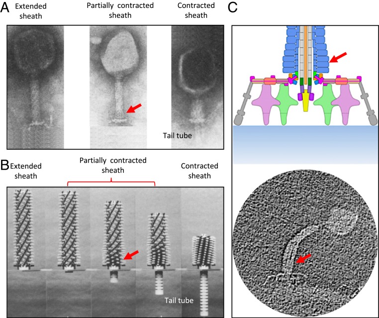
Subsequently, Moody (11) hypothesized a possible “contraction wave” pathway for sheath contraction from snapshots captured by electron micrographs of partially contracted sheaths in vitro. He hypothesized that the sheath contraction mechanism is likely displacive (11) with contraction initiating at the baseplate and propagating dynamically toward the neck; see Fig. 2A. Interestingly, Caspar (12) built a meter-scale kinematic mechanism to visualize sheath contraction as predicted by Moody; refer to Fig. 2B. In this mechanism, sheath subunits are represented by (white) knobs pinned to circumferential grooves machined in a central rod (representing the tail tube). The sequential release of each ring of knobs from the circumferential grooves allows the mechanism to contract in discrete, static steps. While useful in visualizing Moody’s hypothesis, this static mechanism does not of course mimic the underlying dynamics of a propagating contraction wave.
Fig. 2.
The intermediate structures of the sheath reveal the contraction wave propagating upward from the baseplate toward the neck. (A) Micrographs of phage T4 sheath in the extended, partially contracted, and fully contracted conformations reported by Moody (11). Reprinted from ref. 11, with permission from Elsevier. (B) Steps of phage T4 contraction modeled by Caspar’s mechanical model (12). Reprinted from ref. 12, with permission from Elsevier. (C) The partially contracted intermediate structure of phage A511 (13). Reprinted with permission from ref. 13. The arrows refer to the contracted regions during sheath contraction.
A recent experimental study of bacteriophage A511 by Guerrero-Ferreira et al. (13) confirms the wave propagation mechanism of sheath contraction for contractile injection machineries. Bacteriophage A511, which infects Listeria monocytogenes and Listeria ivanovii, possesses a contractile injection machinery very similar to that of phage T4 (13). The experiment, conducted under near-native conditions, confirms that sheath contraction starts from the baseplate and then propagates toward the neck (Fig. 2C), similar to what is believed to occur in phage T4 (13). Elasticity theory was also employed to describe an approximate (coarse-grained) free-energy surface governing the T4 sheath conformational change (14). Unfortunately, that (static) theory fails to describe the dynamics of the injection process.
In principle, the dynamics of sheath contraction could be simulated with atomic detail using molecular-dynamics (MD) simulations (15), and results could be used to understand the inner workings of all of the structural components described above. However, the atomic structure of phage T4 is an extremely large system, one that incorporates (multiple) millions of atoms. In addition, the timescales currently achievable by MD simulations for such large systems fall far short (by approximately 6 orders of magnitude) of the expected millisecond or longer timescales for sheath contraction. Thus, it is presently impossible to simulate the entire T4 injection machinery at atomistic resolution and over biologically relevant (e.g., millisecond) timescales using today’s computing power.
An attractive alternative is to leverage coarse-grained continuum models of the actively changing protein structures, and specifically the contractile sheath. In particular, a nonlinear continuum model of the sheath should be capable of resolving the large conformational changes of the sheath that powers the entire injection process and over biologically relevant timescales (16, 17). Building on that approach, this paper develops a model of the T4 injection machinery coupled to the remainder of the virus and interacting with the host cell. The resulting system-level model reveals the energetics of the injection machinery, the timescale of the injection process, the dynamical pathway of sheath contraction including the propagating contraction wave, the energy dissipation mechanisms, and the forces developed to rupture the host cell.
Methods
The dynamics of the injection process is governed by the competition between two energetic processes: 1) the internal energy released from the sheath that powers the injection, and 2) the dissipation of energy during injection from multiple sources. We provide below brief summaries of the models for each of these energetic processes and further details are provided in SI Appendix.
Dynamic Modeling of the Phage T4 Injection Machinery.
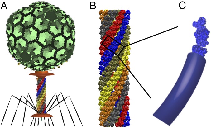
The internal energy that powers the injection machinery derives from the large conformational change of the sheath from the (high-energy) extended state to the (low-energy) contracted state. In essence, the sheath serves as a (kinematically complex) spring that releases the elastic energy stored in its extended state. In turn, this elastic energy is governed by the (dynamically changing) curvature, torsion, and stiffness of the 6 interacting helical protein strands that form the shell-like sheath structure. In the dynamic model for T4, each helical strand is represented by a nonlinear elastic rod with stiffness properties that account for both inter- and intrastrand interactions; see Fig. 3 and details in SI Appendix. The 6 interacting helical rods connect to a rigid (and massive) body representing the capsid/DNA/neck/tube assembly at the upper end of the sheath and the fixed baseplate at the lower end (16). The bending and torsional stiffness constants of the helical protein strands (rods) are estimated from MD simulations of the thermal fluctuations of a fragment of the sheath in both the extended and contracted states (16).
Fig. 3.
Dynamic modeling of contractile sheath of phage T4. (A) The major structural domains of phage T4. (B) The atomistic structure of the T4 sheath consisting of 6 interacting helical strands of gp18 subunits. (C) Representation of each helical protein strand by an elastic rod having equivalent elastic properties.
Mechanisms that Dissipate Energy during Injection.
Four mechanisms that dissipate energy for the phage T4 injection machinery are captured in the model. These include: 1) the hydrodynamic dissipation on the capsid and sheath from the surrounding environment, 2) the internal (material) dissipation of the sheath strands during the large conformational change, 3) the dissipation from the host cell membrane interacting with the tail tube, and 4) the hydrodynamic interactions between the contractile sheath and the tail tube during contraction. To predict the timescale and dynamics of the phage T4 injection machinery, one must quantify and model each dissipation mechanism. Brief descriptions of each mechanism are given below with further details provided in SI Appendix. Their influences on the dynamics of the injection machinery are highlighted in Results and Discussion.
Hydrodynamic Dissipation of Capsid and Sheath.
During sheath contraction, the sheath and capsid are subject to nanoscale hydrodynamic drag forces and moments from the surrounding fluid environment (water) which are modeled using classical (Stokes’s regime) drag laws. The associated drag coefficients follow well-known estimates (18) as also used in ref. 16.
Internal Dissipation of Sheath Strands.
During sheath contraction, the helical protein strands undergo a nonlinear conformational change from the extended state to the contracted state. However, cryo-EM maps reveal no conformational differences of the constituent gp18 subunits between the extended and contracted sheaths (19). Accordingly, it is hypothesized that during contraction, the gp18 subunits forming each strand rotate and translate in forming contacts without significant change to their atomic structure. The resulting strand motion produces internal dissipation (due to forming contacts). At the continuum (rod) level, this is captured by coupled bending and shear deformations. The internal dissipation coefficients for shear and bending are estimated from MD-derived thermal fluctuations (20). To simplify the numerical procedure, the internal dissipation is then modeled by an equivalent external (fluid) dissipation by selecting a fluid viscosity that yields the same net energy dissipation as the internal dissipation; refer to SI Appendix for details.
Cell–Tail Tube Dissipation.
The Gram-negative bacterial cell envelope is a complex structure consisting of the outer membrane, the periplasmic space, and the inner membrane (plasma membrane). During sheath contraction, the tail tube simultaneously rotates and translates downward to pierce and enter this envelope. In doing so, the membrane introduces a reaction force and moment on the tip of the tail tube in a two-stage process. During the first stage, the tip touches and locally deforms (indents) the viscoelastic membrane. This stage, which is modeled by a viscoelastic reaction on the tip (21), persists until the local membrane ruptures following which the tip enters the periplasmic space. Following rupture, the tip is subject to the hydrodynamic drag force and moment of the periplasmic space modeled by classical (Stokes’s flow) drag laws (18).
Sheath–Tail Tube Friction.
Despite the wealth of information on the atomic structure of the sheath and the tail tube, possible interactions between them remain largely unknown. Potential sheath–tube interactions may arise from electrostatic and nonbounded forces and from viscosity in the nanoscale gap (interstitial water) between the tail tube and the surrounding sheath. Importantly, these interactions likely retard the injection process thereby affecting the injection timescale. From cryo-EM data (7, 19, 22), the charge distributions along the inner sheath surface and the outer tail tube surface of phage T4 are relatively uniform (SI Appendix, Fig. S6A). This implies that the net electrostatic and nonbonded forces will be largely perpendicular to the tail tube axis and thus contribute insignificant work as the tail tube translocates through the sheath. By contrast, a significant interaction may arise during translocation from the large viscosity of the interstitial nanoscale gap; see SI Appendix, Fig. S6B. To simulate this friction between the sheath and the tail tube, we employ a classic model of fluid motion between 2 parallel surfaces having linear velocity profiles (SI Appendix, Fig. S7).
Results and Discussion
The energetic mechanisms above that supply and dissipate energy during the injection process are incorporated into a system-level model of the assembled phage T4 interacting with a host cell; refer to details in SI Appendix. Numerical solutions of this system-level model yield predictions of the energetics, the virus–cell interaction forces, the dynamic pathway including the contraction wave, and the overall timescale of the injection process.
Energetics of the Injection Machinery and Virus–Cell Interaction Forces.
The dynamic model of the phage T4 injection machinery estimates the energetics of the entire injection process, including the initial energy stored by the sheath and how that energy is dissipated, and the interaction forces with the host cell.
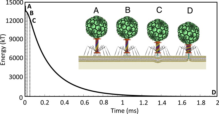
Fig. 4 illustrates the computed internal energy of the 6 sheath strands and how that energy is released as a function of time during the entire injection process. Before contraction (Fig. 4A) the sheath is in the high-energy extended state. The dynamic model estimates that the enthalpy (elastic energy) of the extended state is about 14,500 kT. Also, vibrational analysis reveals that the entropy for the first 70 modes of bending and torsional fluctuations of the sheath is about 200 kT, which is negligibly small relative to the estimated enthalpy of the extended state (∼14,500 kT); see details in SI Appendix. Thus, the contraction process is driven by ∼14,500 kT of enthalpy. Importantly, the estimated elastic energy of the extended sheath is reasonably consistent with the experimentally reported enthalpy of the sheath during heat-induced contraction (∼10,000 kT) (10). However, we emphasize again that heat-induced contraction initiates contraction by a nonphysiological mechanism; namely, by breaking the bonds between the sheath and the baseplate (10). Moreover, heat-induced contraction occurs at high temperature (∼70 °C) that also induces some denaturation of the gp18 molecules (10). By contrast, the dynamic model considers T4 in its native state (i.e., room temperature) with contraction induced by the physiological mechanism (following the conformational change of the baseplate). These important distinctions may explain the remaining difference between these theoretical and experimental energy estimates.
Fig. 4.
Complete dynamic model of the T4 injection machinery interacting with the host cell predicts the internal energy of the contractile sheath that drives the injection process. (A) The sheath begins in the (high-energy) extended state where the tip of the tail tube remains 100 Å from the cell membrane. (B) The sheath contracts about 100 Å so that the tip of the tail tube touches the outer cell membrane. (C) Further contraction of the sheath produces, in sequence, cell indentation, rupture of the outer cell membrane (after 60-Å indentation), and penetration into the (viscous) periplasmic space. (D) The fully contracted sheath with zero elastic energy. Note that in this simulation, and
Beyond these estimates of the initial energy stored in the extended sheath, the model further predicts the energetics of the sheath during the entire contraction process, which has not been previously studied. Following the conformational change of the baseplate, the tail tube (and the attached sheath) are released from the grip of the baseplate which initiates the rapid energetic release depicted in Fig. 4. As the sheath contracts, the tail tube first touches the outer cell membrane (Fig. 4B) and further contraction leads to increasing cell indentation (Fig. 4C) and ultimately cell rupture. Following that event, the tip of the tail tube enters the periplasmic space subject to additional drag (Fig. 4D). The injection concludes when the tail tube has translated the total distance ∼500 Å from its starting position. Overall, the injection process is highly overdamped (evident from Fig. 4) and thus the kinetic energy of the injection machinery remains quite small relative to the initial energy stored in the sheath.
During sheath contraction, the elastic energy stored in the extended sheath is dissipated through the 4 energy dissipation mechanisms discussed above. Of these mechanisms, the parameters describing the hydrodynamic dissipation on the capsid/sheath and the cell–tail tube dissipation are reasonably well understood; refer to SI Appendix. However, the 2 remaining mechanisms, namely, the internal dissipation of the sheath strands and the dissipation due to sheath–tail tube friction, are lesser understood. Thus, following systematic reasoning, we select a range of model parameters for the 2 unknown mechanisms to study their contributions to the energetics of sheath contraction.
The friction coefficient governing the internal dissipation of the sheath strands is estimated to be 0.005 Pa⋅s from MD-derived thermal fluctuations (refer to SI Appendix), which is on the order of the viscosity of bulk water. However, the amplitude of the fluctuations in the MD simulations are on atomistic length scales, whereas the sheath undergoes a conformational change that is several orders of magnitude larger. Consequently, the friction coefficient may actually be far greater and perhaps similar to that of thermally fluctuating actin filaments (1 Pa⋅s) which is about 3 orders of magnitude greater than the viscosity of bulk water (23). Consequently, in the following, we explore behaviors over a wide range of values . Similarly, the sheath–tail tube friction coefficient may vary considerably with the properties of the interstitial nanoscale gap between the sheath and tail tube. The water confined to this gap exhibits distinct viscosity characteristics compared to bulk water and these characteristics strongly depend on the gap thickness and the degree of surface hydrophilicity/hydrophobicity. Experimental studies (24, 25) reveal that the greater the affinity between the water molecules and the surfaces forming the nanoscale gap, the greater the effective viscosity. For example, the viscosity of water confined to a 1.3-nm gap between an oxide-terminated tip of an interfacial force microscope and a silica surface is about 6 orders of magnitude greater than the viscosity of bulk water (24). From experimental data, the nanochannel between the tube and sheath is largely hydrophilic (SI Appendix, Fig. S6B), resulting in an effective viscosity that may be significantly greater than that of bulk water. Accordingly, we explore behaviors over a wide range of values encompassing values for bulk water to nanoscale layers with highly hydrophilic surfaces (24). Note that in the simulations for Fig. 4, and
Fig. 5 illustrates the relative (%) energy dissipation due to all 4 dissipation mechanisms for select values of and within the above ranges. Doing so reveals the possible regimes where each dissipation source may dominate. For instance, at the lower limits ( and ), the dominant dissipation mechanism derives from cell–tail tube dissipation; refer to CTTD (cell-tail tube dissipation) in Fig. 5A. However, for and , the dominant dissipation mechanism becomes the internal dissipation of the sheath strands; refer to IDSS (internal dissipation of the sheath strands) in Fig. 5B. Finally, sheath–tail tube friction becomes the dominant dissipation mechanism for , regardless of ; refer to STTF (sheath–tail tube friction) in Fig. 5C. Interestingly, the hydrodynamic dissipation on the capsid/sheath always remains of secondary or lower importance; refer to HDCS (hydrodynamic dissipation on the capsid/sheath) in Fig. 5. Overall, these results demonstrate that several mechanisms are likely responsible for dissipating the initial energy stored in the sheath. The analysis of energy dissipation remains an intriguing avenue for future experimental and theoretical research, particularly given that energy dissipation plays a governing role in establishing the timescale of the injection process as discussed below.
Fig. 5.
Complete dynamic model of the T4 injection machinery interacting with the host cell predicts the relative (%) contribution of all 4 dissipation mechanisms during injection. (A) For and , CTTD emerges as the dominant source of energy dissipation. (B) For and , IDSS emerges as the dominant source of energy dissipation. (C) For and , STTF emerges as the dominant source of energy dissipation.
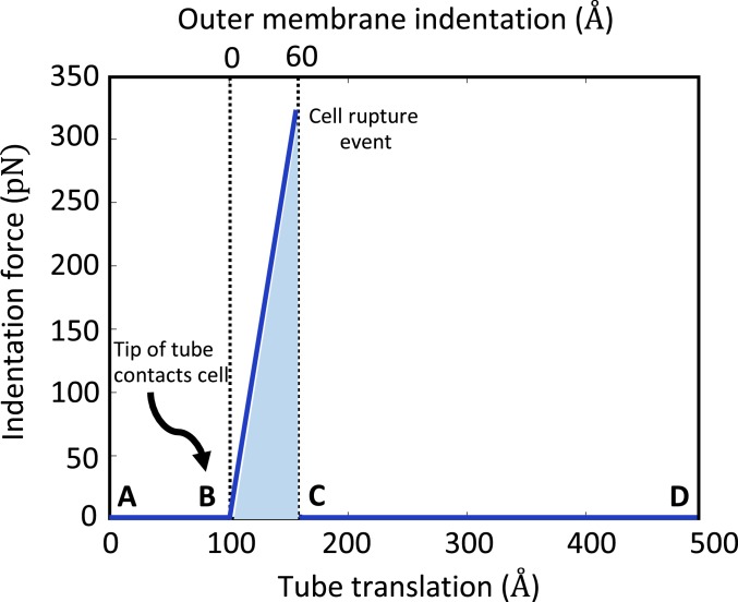
Our dynamic model presents a prediction of the rupture mechanics of the host membrane (E. coli) by phage T4; see Fig. 6. While the rupture force (or stress) for E. coli remains unknown, experimental studies on lipid bilayers (26) (which mimic the outer cell membrane) yield a starting point for the model. Those experiments employ an atomic force microscope with a pyramidal tip to rupture the lipid bilayer with a force of greater than 10 nN (26). Assuming that E.coli (with distinct stiffness from a lipid bilayer) has approximately the same rupture stress as the lipid bilayer, we predict that the required force to rupture the cell membrane by the 9-Å-diameter (27) tip of the tail tube is greater than 330 pN and that occurs at an indentation of ∼60 Å. Fig. 6 illustrates the indentation force on the membrane from the tail tube estimated from the system model as a function of both the tail tube displacement (bottom scale) and the outer membrane indentation (top scale). Following contact of the tail tube on the outer membrane (starting at tube displacement 100 Å), the indentation force increases with additional tube displacement up to point of membrane rupture (following which it returns to zero again). We estimate that rupture occurs at a force of 330 pN which also occurs when the tube translates 160 Å (or equivalently when the indentation of membrane reaches 60 Å). Note that the work done by phage T4 to rupture the host membrane (shaded area in Fig. 6) is about 250 kT which is much less than total energy (∼14,500 kT) stored in the extended sheath. Consequently, the initial energy of the sheath is largely dissipated during the injection process.
Fig. 6.
Complete dynamic model of the T4 injection machinery interacting with the host cell predicts the rupture mechanics of the host cell membrane during the injection process. Indentation force illustrated as the function of indentation of the outer membrane (scale at top) and as the function of the tail tube translation (scale at bottom). (A and B) The tail tube before contact with the outer membrane. The indentation and indentation force remain zero. (B and C) The tail tube during contact with the outer membrane. The resulting indentation and force increase until rupture of the outer membrane (rupture force 330 pN, rupture indentation 60 Å). (C and D) The tail tube after rupture while translating through periplasmic space. Indentation and force return to zero. The injection machinery in states A–D are illustrated in Fig. 4 A–D, respectively.
Dynamic Pathway of the Injection Process.
The dynamic model of the phage T4 injection machinery reveals the conformational change of the sheath as a nonlinear contraction wave and the companion dynamics of the attached capsid/neck/tail tube assembly.
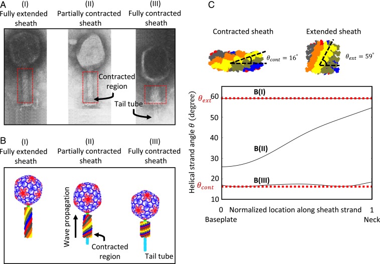
During sheath contraction, the sheath subunits translate and rotate during the large conformational change from the extended state to the contracted state. From the micrographs of partially contracted sheaths (Fig. 2A) (11), Moody hypothesized that the sheath contraction is displacive whereby the subunits forming a single ring displace identically and in unison to produce a contraction wave that propagates upward from the baseplate (adjacent to first ring) to the neck (adjacent to last ring); Fig. 7 A, I–III. Importantly, the intermediate micrographs of phage A511 in native experimental conditions confirm the wave propagation mechanism of sheath contraction from the baseplate to the neck (Fig. 2C) (13) for contractile bacteriophages like T4. Our MD simulations also reveal that, due to changes in the sheath subunit contacts, the elastic stiffness constants of the sheath strands in the contracted state are larger than those in the extended state; SI Appendix, Table S1.
Fig. 7.
Complete dynamic model of the T4 injection machinery interacting with the host cell reveals contraction dynamics of the sheath from the fully extended conformation to the fully contracted conformation, consistent with the experimental micrographs reported by Moody (11). (A) Micrographs of sheath reported by Moody (11) in the extended (I), partially contracted (II), and fully contracted (III) conformations. Reprinted from ref. 11, with permission from Elsevier. (B) The snapshots of sheath from complete dynamic model of T4 interacting with the host cell in the extended (I), partially contracted (II), and fully contracted (III) conformations. Intermediate conformation (II) captures contraction wave propagation from the (lower) baseplate toward the (upper) neck, consistent with A, II. (C) The helical strand angle as a function of location along the strand. As the contraction wave passes, the helical strand angle decreases from that of the extended conformation B, I with ° to that of the contracted conformation B, III with °.
Consistent with experimental observations (11, 13) and our MD-derived stiffness constants, we propose the following sheath contraction model. Prior to injection, the sheath remains in the extended conformation wherein interactions between the sheath and tail tube subunits retain the sheath in the high-energy state. Sheath contraction is triggered by a large conformational change of the baseplate that breaks the interactions between the local sheath–tail tube subunits enabling displacive contraction starting at the first ring of sheath subunits. The sheath–tube subunit interactions are then broken sequentially upward in each ring from the baseplate toward the neck, enabling the sheath subunits to rotate and translate in forming contacts and thus local stiffness properties. As a consequence, an intermediate conformation of the sheath would consist of a partially contracted region extending upward from the baseplate possessing larger elastic stiffness constants (similar to the fully contracted sheath) and a partially extended sheath (extending downward from the neck) possessing smaller elastic stiffness constants. Hence, the resulting intermediate would possess nonhomogeneous stiffness constants as included in the model per the details provided in SI Appendix.
The model simulation captures this dynamic contraction wave starting from the computed dynamic conformations of the 6 interacting helical gp18 protein strands that form the sheath. In particular, the continuum (rod) model for each strand yields the strand centerline that passes through the mass centers of the constituent gp18 subunits. From the known centerlines of each strand, we then reconstruct approximate atomistic representations of the entire sheath as detailed in SI Appendix. The approximate atomistic sheath representations at each time step are further combined with atomistic representations of the tail tube, capsid, and neck to form an animation of the dynamic contraction process for the phage T4; refer to Movie S1. As illustrated in Movie S1, the contraction wave propagates from the baseplate toward the neck. The movie further reveals that the sheath contracts rapidly at the beginning and then slowly at the end, consistent with the results of Fig. 4 that exhibit exponentially decaying energy. Fig. 7 compares selected snapshots of the simulated injection dynamics with the experimental micrographs images provided by Moody (11). In particular, Fig. 7B illustrates the fully extended (I), a partially contracted (II), and the fully contracted (III) sheath as selected from the movie frames. These images, representing the computed output from the system model, are consistent with the experimental micrograph images in Fig. 7A for the fully extended (I), a partially contracted (II), and fully contracted (III) sheath reported by Moody (11).
As the contraction wave passes, the helical strand angle illustrated in Fig. 7C decreases and the helical strand radius increases. The resulting “wave front” of the propagating contraction wave is best visualized in Fig. 7C that shows the helical strand angle as a function of location along the strand for the fully extended, a partially contracted, and the fully contracted sheath strands. Note that the helical strand angle is reduced by ∼45° during contraction and that rotation begins at the baseplate and propagates upward along each strand to the neck. This finding is consistent with the cryo-EM data that reveal that the sheath subunits rotate ∼45° about the radial axis passing through the subunits following contraction (19).
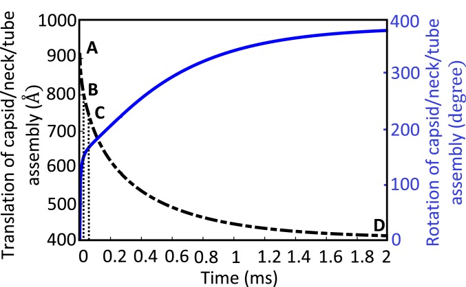
As discussed in the context of Fig. 4, before contraction, the sheath starts in its (high-energy) extended conformation with the tip of the tail tube poised about 100 Å (9) from the cell surface (Fig. 4A). As the sheath contracts, the tail tube first touches the outer cell membrane (Fig. 4B) after the tip of the tail tube translates about 100 Å. Further contraction leads to cell indentation (Fig. 4C) and ultimately cell rupture at an estimated cell indentation of ∼60 Å. Thereafter, the tail tube translates through the highly viscous periplasmic space (Fig. 4 C and D). Fig. 8 reports the dynamics of this process by illustrating the simultaneous translation and rotation of the capsid/neck/tail tube assembly along/about the tail tube axis as functions of time. Note that, over the entire injection process, the capsid/neck/tail tube assembly translates downward by about 500 Å and rotates approximately 1 turn counterclockwise (when viewed from above the capsid) about the tube axis which is consistent with cryo-EM data for the extended and contracted sheath (8). Moreover, this figure reveals that the dynamic contraction grows rapidly at the start of injection and decays exponentially at the end; note the coupled translation and rotation of the capsid in Movie S1. The initial rapid translation with rotation provides a 2-punch mechanism for mechanically rupturing the outer cell membrane (Fig. 8 A–C).
Fig. 8.
Complete dynamic model of the T4 injection machinery interacting with the host cell predicts the dynamic rotation and translation of the capsid/neck/tail tube assembly during the injection process. Solid curve illustrates the rotation and dashed curve illustrates the translation. The injection machinery at states A–D are illustrated in Fig. 4 A–D, respectively. Note, in this simulation, and .
Dissipation Controls the Timescale of the Injection Process.
We also employ the model to explore the overall timescale of sheath contraction from the extended state to the contracted state, another important characteristic of the injection process that has so far eluded experimental determination. As mentioned above, this timescale is highly dependent on the dominant energy dissipation mechanism. At one extreme, the model predicts an injection timescale of only several microseconds if the only source of dissipation is the hydrodynamic drag on the capsid and sheath; refer to ref. 16. However, such a short timescale is highly unlikely given the overriding influence of the other 3 dissipation mechanisms considered herein and, as emphasized above, the hydrodynamic drag on the capsid/sheath remains only of secondary or lesser importance.
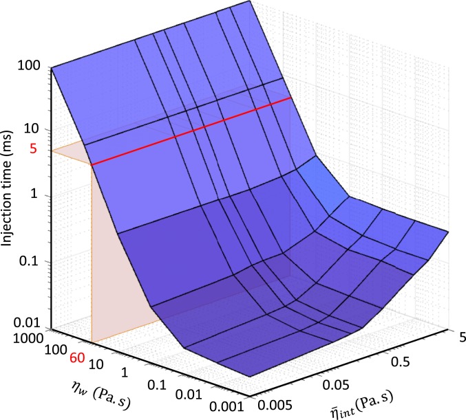
For instance, upon adding cell–tail tube interaction to the dynamic model, the timescale of the injection process increases to as this dissipation mechanism is significantly greater than the hydrodynamic drag on the capsid and sheath. However, this increased timescale is still likely far too short. The main question is, what is the likely range of the timescale given the acknowledged uncertainties in the parameters and for the 2 dominant dissipation mechanisms described above? To address this, we first explore how the injection timescale varies over the broad ranges and . Over these ranges, the computed injection time varies from the microsecond scale to 100 ms. In particular, for , the injection time remains approximately on the order of microseconds for all values of . By contrast, for , the injection time rapidly grows to the millisecond timescale; refer to Fig. 9. In this range , the dominant energy dissipation mechanism derives from STTF as discussed above.
Fig. 9.
Complete dynamic model of the T4 injection machinery interacting with the host cell predicts the timescale of the injection process as a function of the sheath–tube gap viscosity coefficient over the range and the internal friction coefficient over the range . Note log scales. Red region defines a likely injection timescale for T4 (∼5 ms) by drawing a comparison with that of the T6SS (26).
Next, we focus on the parameter range that yields likely injection times by taking a cue from experimental results. While there are presently no experimental results that resolve the injection time for T4, there are data for the Type VI secretion system (T6SS), which is a headless, contractile tail system used to inject toxic effectors into competing bacterial cells (28), and which has a similar molecular architecture with the T4 contractile tail. Recent experiments on T6SS report that the timescale of sheath contraction is ∼5 ms or less (29). Despite obvious morphological differences between phage T4 and T6SS (head versus headless) and the injected material (DNA versus toxic effectors), their actual injection machineries possess remarkable similarities. Both injection machineries possess a long rigid tail tube surrounded by an elastic sheath that is formed by 6 interacting helical protein strands. Furthermore, both sheaths power the injection process by contracting from high-energy extended states to low-energy contracted states (28). Given these significant structural similarities of the injection machineries, one might also anticipate similar injection times. Proceeding under that assumption, we identify the region within Fig. 9 that yields similar injection times; refer to region in red defining an injection time of 5 ms. If we assume that the timescales of sheath contraction for phage T4 and T6SS are approximately the same, then the corresponding value for would be (Fig. 9) which is approximately 4 orders of magnitude greater than the viscosity of bulk water (0.001 Pa⋅s), yet substantially below the extreme value (1000 Pa⋅s) for nanoscale layers with highly hydrophilic surfaces (24). In this region, the internal energy dissipation exerts only weak influence on the injection time (see the red line in Fig. 9 which remains largely insensitive across the range ). Thus, the energy dissipation from the STTF emerges as the likely dominant dissipation mechanism controlling the injection timescale.
Contributions and Conclusions
This study contributes a system-level model of bacteriophage T4 interacting with a host cell that predicts the global dynamics of the intriguing and complex injection machinery by simulating all aspects that control its behavior. In particular, the system model predicts the dynamical pathway of sheath contraction in the form of a contraction wave, the energy that powers the injection machinery, the forces responsible for piercing the host cell membrane, and the energy dissipation that controls the timescale of the injection process.
The dynamics of the injection process is governed by the competition between 2 energetic processes; namely, the stored energy of the contractile sheath that powers the injection and the dissipation mechanisms that retard the injection dynamics. Accordingly, the system model couples component models of the contractile sheath (elastic), the neck/capsid/tail tube (rigid), the host cell (viscoelastic), and 4 energy dissipation mechanisms. The elastic sheath model, formed by 6 interacting helical protein strands (rods), captures the large conformational change of the sheath from its (high-energy) extended state preinjection to its (low-energy) contracted state postinjection. The resulting continuum model for the elastic sheath employs elastic constants determined a priori from MD simulations. The sources of energy dissipation include the hydrodynamic dissipation on the capsid and sheath from the surrounding environment, the internal dissipation of the sheath strands, the dissipation from the host cell membrane interacting with the tip of the tail tube, and the hydrodynamic interaction between the sheath and the tail tube. The component model of the tip of the tail tube interacting with the host cell also yields estimates of the forces exerted on the host cell membrane. The findings and major conclusions drawn from this system model follow.
The model estimates that the injection process is driven by ∼14,500 kT of elastic energy stored in the extended sheath. This estimate is consistent with the experimentally reported enthalpy of sheath contraction (10). The dynamical pathway underlying the injection process takes the form of a contraction wave that propagates from the baseplate to the neck as revealed in the animated results (refer to Movie S1) and as previously hypothesized (11, 12). The simulated conformations of T4 during contraction are consistent with the experimental micrographs of extended, partially contracted, and fully contracted particles observed in in vitro experiments (11) and they also provide further potential starting points for future, detailed free-energy calculations at the atomic level. Dynamic sheath contraction induces initial rapid translation and rotation of the tail tube (and capsid) to rapidly generate the forces needed to rupture the outer membrane of the host cell. Indeed, the model estimates that rupture arises when the tip of the tail tube exerts a force greater than 330 pN at an indentation of ∼60 Å. The model enables broad exploration of the 4 energy dissipation mechanisms and doing so reveals the mechanisms (and parameter ranges) that control the overall timescale of the injection process. In particular, injection times on the millisecond timescale [and as observed for the analogous T6SS (29)] are controlled by sheath-tail tube friction.
The system model summarized herein may be further expanded to explore how other contractile tail-driven injection machineries work, such as R-pyocins and bacteriophage phi812. R-pyocins are headless injection machineries that attack competing bacteria by channeling protons to their competition, thereby dissipating their membrane potential (30). Phage phi812, also from the family Myoviridae, infects Staphylococcus aureus (31). Despite differences in morphology, R-pyocins and phi812 (as well as T6SS) share a remarkably common structure in their injection machinery, namely, they all possess a contractile sheath composed of 6 interacting helical protein strands that drives the injection process. Studying the structure, function, and dynamics of these nanoinjection machineries has important implications for future bionanotechnologies.
Data Availability.
The authors declare that the data supporting the findings of this study are available within the article and its supporting information file. The simulation protocols are also available from the corresponding author upon reasonable request.
Supplementary Material
Acknowledgments
We thank Moises Ernesto Romero for advice on creating Movie S1. This study is based upon work supported by the NSF under Grant CMMI-1404747.
Footnotes
The authors declare no competing interest.
This article is a PNAS Direct Submission.
This article contains supporting information online at https://www.pnas.org/lookup/suppl/doi:10.1073/pnas.1909298116/-/DCSupplemental.
References
- 1.Fokine A., et al. , Molecular architecture of the prolate head of bacteriophage T4. Proc. Natl. Acad. Sci. U.S.A. 101, 6003–6008 (2004). [DOI] [PMC free article] [PubMed] [Google Scholar]
- 2.Rossmann M. G., Mesyanzhinov V. V., Arisaka F., Leiman P. G., The bacteriophage T4 DNA injection machine. Curr. Opin. Struct. Biol. 14, 171–180 (2004). [DOI] [PubMed] [Google Scholar]
- 3.Kostyuchenko V. A., et al. , Three-dimensional structure of bacteriophage T4 baseplate. Nat. Struct. Biol. 10, 688–693 (2003). [DOI] [PubMed] [Google Scholar]
- 4.Prehm P., Jann B., Jann K., Schmidt G., Stirm S., On a bacteriophage T3 and T4 receptor region within the cell wall lipopolysaccharide of Escherichia coli B. J. Mol. Biol. 101, 277–281 (1976). [DOI] [PubMed] [Google Scholar]
- 5.Hu B., Margolin W., Molineux I. J., Liu J., Structural remodeling of bacteriophage T4 and host membranes during infection initiation. Proc. Natl. Acad. Sci. U.S.A. 112, E4919–E4928 (2015). [DOI] [PMC free article] [PubMed] [Google Scholar]
- 6.Yap M. L., et al. , Role of bacteriophage T4 baseplate in regulating assembly and infection. Proc. Natl. Acad. Sci. U.S.A. 113, 2654–2659 (2016). [DOI] [PMC free article] [PubMed] [Google Scholar]
- 7.Leiman P. G., Chipman P. R., Kostyuchenko V. A., Mesyanzhinov V. V., Rossmann M. G., Three-dimensional rearrangement of proteins in the tail of bacteriophage T4 on infection of its host. Cell 118, 419–429 (2004). [DOI] [PubMed] [Google Scholar]
- 8.Kostyuchenko V. A., et al. , The tail structure of bacteriophage T4 and its mechanism of contraction. Nat. Struct. Mol. Biol. 12, 810–813 (2005). [DOI] [PubMed] [Google Scholar]
- 9.Simon L. D., Infection of Escherichia coli by T2 and T4 bacteriophages as seen in the electron microscope: T4 head morphogenesis. Proc. Natl. Acad. Sci. U.S.A. 69, 907–911 (1972). [DOI] [PMC free article] [PubMed] [Google Scholar]
- 10.Arisaka F., Engel J., Klump H., Contraction and dissociation of the bacteriophage T4 tail sheath induced by heat and urea. Prog. Clin. Biol. Res. 64, 365–379 (1981). [PubMed] [Google Scholar]
- 11.Moody M. F., Sheath of bacteriophage T4. 3. Contraction mechanism deduced from partially contracted sheaths. J. Mol. Biol. 80, 613–635 (1973). [DOI] [PubMed] [Google Scholar]
- 12.Caspar D. L., Movement and self-control in protein assemblies. Quasi-equivalence revisited. Biophys. J. 32, 103–138 (1980). [DOI] [PMC free article] [PubMed] [Google Scholar]
- 13.Guerrero-Ferreira R. C., et al. , Structure and transformation of bacteriophage A511 baseplate and tail upon infection of Listeria cells. EMBO J. 38, e99455 (2019). [DOI] [PMC free article] [PubMed] [Google Scholar]
- 14.Falk W., James R. D., Elasticity theory for self-assembled protein lattices with application to the martensitic phase transition in bacteriophage T4 tail sheath. Phys. Rev. E. Stat. Nonlin. Soft Matter Phys. 73, 011917 (2006). [DOI] [PubMed] [Google Scholar]
- 15.Karplus M., McCammon J. A., Molecular dynamics simulations of biomolecules. Nat. Struct. Biol. 9, 646–652 (2002). [DOI] [PubMed] [Google Scholar]
- 16.Maghsoodi A., Chatterjee A., Andricioaei I., Perkins N. C., Dynamic model exposes the energetics and dynamics of the injection machinery for bacteriophage T4. Biophys. J. 113, 195–205 (2017). [DOI] [PMC free article] [PubMed] [Google Scholar]
- 17.Maghsoodi A., Chatterjee A., Andricioaei I., Perkins N. C., A first model of the dynamics of the bacteriophage T4 injection machinery. J. Comput. Nonlinear Dyn. 11, 041026 (2016). [Google Scholar]
- 18.Howard J., Mechanics of Motor Proteins and the Cytoskeleton (Sinauer Associates, Sunderland, MA, 2001). [Google Scholar]
- 19.Aksyuk A. A., et al. , The tail sheath structure of bacteriophage T4: A molecular machine for infecting bacteria. EMBO J. 28, 821–829 (2009). [DOI] [PMC free article] [PubMed] [Google Scholar]
- 20.Maghsoodi A., Perkins N., Shear deformation dissipates energy in biofilaments. Sci. Rep. 8, 11684 (2018). [DOI] [PMC free article] [PubMed] [Google Scholar]
- 21.Vadillo-Rodriguez V., Dutcher J. R., Dynamic viscoelastic behavior of individual Gram-negative bacterial cells. Soft Matter 5, 5012–5019 (2009). [Google Scholar]
- 22.Taylor N. M. I., et al. , Structure of the T4 baseplate and its function in triggering sheath contraction. Nature 533, 346–352 (2016). [DOI] [PubMed] [Google Scholar]
- 23.Poirier M. G., Marko J. F., Effect of internal friction on biofilament dynamics. Phys. Rev. Lett. 88, 228103 (2002). [DOI] [PubMed] [Google Scholar]
- 24.Goertz M. P., Houston J. E., Zhu X. Y., Hydrophilicity and the viscosity of interfacial water. Langmuir 23, 5491–5497 (2007). [DOI] [PubMed] [Google Scholar]
- 25.Pawlak Z., Urbaniak W., Oloyede A., The relationship between friction and wettability in aqueous environment. Wear 271, 1745–1749 (2011). [Google Scholar]
- 26.Redondo-Morata L., Giannotti M. I., Sanz F., AFM-based force-clamp monitors lipid bilayer failure kinetics. Langmuir 28, 6403–6410 (2012). [DOI] [PubMed] [Google Scholar]
- 27.Browning C., Shneider M. M., Bowman V. D., Schwarzer D., Leiman P. G., Phage pierces the host cell membrane with the iron-loaded spike. Structure 20, 326–339 (2012). [DOI] [PubMed] [Google Scholar]
- 28.Basler M., Type VI secretion system: Secretion by a contractile nanomachine. Philos. Trans. R. Soc. Lond. B Biol. Sci. 370, 20150021 (2015). [DOI] [PMC free article] [PubMed] [Google Scholar]
- 29.Basler M., Pilhofer M., Henderson G. P., Jensen G. J., Mekalanos J. J., Type VI secretion requires a dynamic contractile phage tail-like structure. Nature 483, 182–186 (2012). [DOI] [PMC free article] [PubMed] [Google Scholar]
- 30.Ge P., et al. , Atomic structures of a bactericidal contractile nanotube in its pre- and postcontraction states. Nat. Struct. Mol. Biol. 22, 377–383 (2015). [DOI] [PMC free article] [PubMed] [Google Scholar]
- 31.Nováček J., et al. , Structure and genome release of Twort-like Myoviridae phage with a double-layered baseplate. Proc. Natl. Acad. Sci. U.S.A. 113, 9351–9356 (2016). [DOI] [PMC free article] [PubMed] [Google Scholar]
Associated Data
This section collects any data citations, data availability statements, or supplementary materials included in this article.
Supplementary Materials
Data Availability Statement
The authors declare that the data supporting the findings of this study are available within the article and its supporting information file. The simulation protocols are also available from the corresponding author upon reasonable request.


