

Abstract
Brain-machine interfaces hold promise for the restoration of sensory and motor function and the treatment of neurological disorders, but clinical brain-machine interfaces have not yet been widely adopted, in part, because modest channel counts have limited their potential. In this white paper, we describe Neuralink’s first steps toward a scalable high-bandwidth brain-machine interface system. We have built arrays of small and flexible electrode “threads,” with as many as 3072 electrodes per array distributed across 96 threads. We have also built a neurosurgical robot capable of inserting six threads (192 electrodes) per minute. Each thread can be individually inserted into the brain with micron precision for avoidance of surface vasculature and targeting specific brain regions. The electrode array is packaged into a small implantable device that contains custom chips for low-power on-board amplification and digitization: The package for 3072 channels occupies less than 23×18.5×2 mm3. A single USB-C cable provides full-bandwidth data streaming from the device, recording from all channels simultaneously. This system has achieved a spiking yield of up to 70% in chronically implanted electrodes. Neuralink’s approach to brain-machine interface has unprecedented packaging density and scalability in a clinically relevant package.
Keywords: brain-machine interface, sensory function, motor function, neurology
Introduction
Brain-machine interfaces have the potential to help people with a wide range of clinical disorders. For example, researchers have demonstrated human neuroprosthetic control of computer cursors [1-3], robotic limbs [4,5], and speech synthesizers [6] by using no more than 256 electrodes. Although these successes suggest that high-fidelity information transfer between brains and machines is possible, development of brain-machine interface has been critically limited by the inability to record from large numbers of neurons. Noninvasive approaches can record the average of millions of neurons through the skull, but this signal is distorted and nonspecific [7,8]. Invasive electrodes placed on the surface of the cortex can record useful signals, but they are limited in that they average the activity of thousands of neurons and cannot record signals deep in the brain [9]. Most brain-machine interfaces have used invasive techniques, because the most precise readout of neural representations requires recording single action potentials from neurons in distributed, functionally linked ensembles [10].
Microelectrodes are the gold-standard technology for recording action potentials, but there is no clinically translatable microelectrode technology for large-scale recordings [11]. This would require a system with material properties that provide high biocompatibility, safety, and longevity. Moreover, this device would also need a practical surgical approach and high-density, low-power electronics to ultimately facilitate fully implanted wireless operation.
Most devices for long-term neural recording are arrays of electrodes made from rigid metals or semiconductors [12-18]. Although rigid metal arrays facilitate penetrating the brain, the size, Young modulus, and bending stiffness mismatches between stiff probes and brain tissue can drive immune responses that limit the function and longevity of these devices [19,11]. Furthermore, the fixed geometry of these arrays constrains the populations of neurons that can be accessed, especially due to the presence of vasculature.
An alternative approach is to use thin, flexible multielectrode polymer probes [20,21]. The smaller size and increased flexibility of these probes should offer greater biocompatibility. However, a drawback of this approach is that thin polymer probes are not stiff enough to directly insert into the brain; their insertion must be facilitated by stiffeners [22,21], injection [23,24], or other approaches [25], all of which are quite slow [26,27]. To satisfy the functional requirements for a high-bandwidth brain-machine interface, while taking advantage of the properties of thin-film devices, we developed a robotic approach, where large numbers of fine and flexible polymer probes are efficiently and independently inserted across multiple brain regions [28].
Here, we report Neuralink’s progress toward a flexible, scalable brain-machine interface that increases channel count by an order of magnitude over prior work. Our system has three main components: ultra-fine polymer probes, a neurosurgical robot, and custom high-density electronics (all of which are described below). We demonstrate the rapid implantation of 96 polymer threads, each thread with 32 electrodes, yielding a total of 3072 electrodes.
We developed miniaturized custom electronics that allow us to stream full broadband electrophysiology data simultaneously from all these electrodes (described below). We packaged this system for long-term implantation and developed custom online spike-detection software that can detect action potentials with low latency. Together, this system serves as a state-of-the-art research platform and the first prototype toward a fully implantable human brain-machine interface.
Threads
We have developed a custom process to fabricate minimally displacive neural probes that employ a variety of biocompatible thin film materials. The main substrate and dielectric used in these probes is polyimide, which encapsulates a gold thin film trace. Each thin film array is composed of a “thread” area that features electrode contacts and traces and a “sensor” area where the thin film interfaces with custom chips that enable signal amplification and acquisition. A wafer-level microfabrication process enables high-throughput manufacturing of these devices. Ten thin film devices are patterned on a wafer, each with 3072 electrode contacts.
Each array has 48 or 96 threads, each of which contain 32 independent electrodes. Integrated chips are bonded to the contacts on the sensor area of the thin film using a flip-chip bonding process. One goal of this approach is to maintain a small thread cross-sectional area to minimize tissue displacement in the brain. To achieve this, while keeping the channel count high, stepper lithography and other microfabrication techniques are used to form the metal film at submicron resolution.
We have designed and manufactured over 20 different thread and electrode types into our arrays; two example designs are shown in Figure 1A and B. Probes are designed either with the reference electrodes on separate threads or on the same threads as the recording electrodes (referred to as “on-probe references”). We have fabricated threads ranging from 5 µm to 50 µm in width that incorporate recording sites of several geometries (Figure 1). Thread thickness is nominally 4-6 µm, which includes up to three layers of insulation and two layers of conductor. Typical thread length is approximately 20 mm. To manage these long, thin threads prior to insertion, parylene-c is deposited onto the threads to form a film on which the threads remain attached until the surgical robot pulls them off. Each thread ends in a 16×50 µm2 loop to accommodate needle threading.
Figure 1.
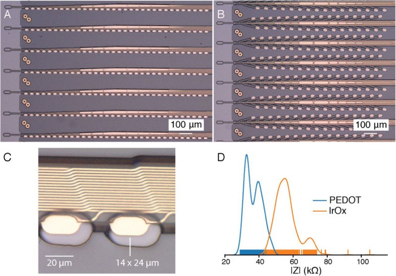
Our novel polymer probes. (A) “Linear Edge” probes, with 32 electrode contacts spaced by 50 μm. (B) “Tree” probes with 32 electrode contacts spaced by 75 μm. (C) Increased magnification of individual electrodes for the thread design in panel A, emphasizing their small geometric surface area. (D) Distribution of electrode impedances (measured at 1 kHz) for two surface treatments: PEDOT (n=257) and IrOx (n=588). IrOx: iridium oxide; PEDOT: poly-ethylenedioxythiophene; PCB: printed circuit board.
Since the individual gold electrode sites have small geometric surface areas (Figure 1C), we use surface modifications to lower the impedance for electrophysiology and increase the effective charge-carrying capacity of the interface (Figure 1D). Two such treatments that we have used are the electrically conductive polymer poly-ethylenedioxythiophene doped with polystyrene sulfonate (PEDOT:PSS) [29,30] and iridium oxide (IrOx) [31,32]. In benchtop testing, we have achieved impedances of 36.97 (SD 4.68) kΩ (n=257 electrodes) and 56.46 (SD 7.10) kΩ (n=588) for PEDOT:PSS and IrOx, respectively. The lower impedance of PEDOT:PSS is promising; however, the long-term stability and biocompatibility of PEDOT:PSS are less well established than those for IrOx. These techniques and processes can be improved and further extended to other types of conductive electrode materials and coatings.
To keep the electronics package small, a novel alignment and flip-chip bonding process was developed. Multilevel gold stud bumps are placed throughout the printed circuit board (PCB) to act as alignment guides and temporary holders for the thin film. A custom shuttle is used to handle, align, and place the thin film on the PCB such that holes in the thin film slide around the stud bumps. The thin film is secured into place by applying force to the gold stud bumps, which flattens them into rivets. Next, the integrated chips are bonded directly to both contacts on the sensor area of the thin film and pads on the PCB by using standard flip-chip bonding processes. A custom silicon shuttle is used to vacuum pick-up rows of 40-50 capacitors and bond a total of 192 capacitors onto the PCB. This alignment and bonding process was key to creating a package containing 3072 channels in a 23×18.5 mm2 footprint.
Robot
Thin-film polymers have previously been used for electrode probes [21], but their low bending stiffness complicates insertions. Neuralink has developed a robotic insertion approach for inserting flexible probes [28], allowing rapid and reliable insertion of large numbers of polymer probes targeted to avoid vasculature and record from dispersed brain regions. The robot’s insertion head is mounted on a globally accurate, 400×400×150 mm travel, 10-µm three-axis stage and holds a small, quick-swappable “needle-pincher” assembly (Figures 2 and 3A).
Figure 2.
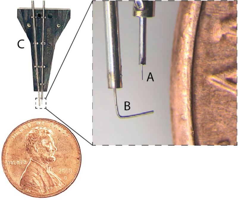
Needle pincher cartridge compared with a penny for scale. (A) Needle. (B) Pincher. (C) Cartridge.
Figure 3.
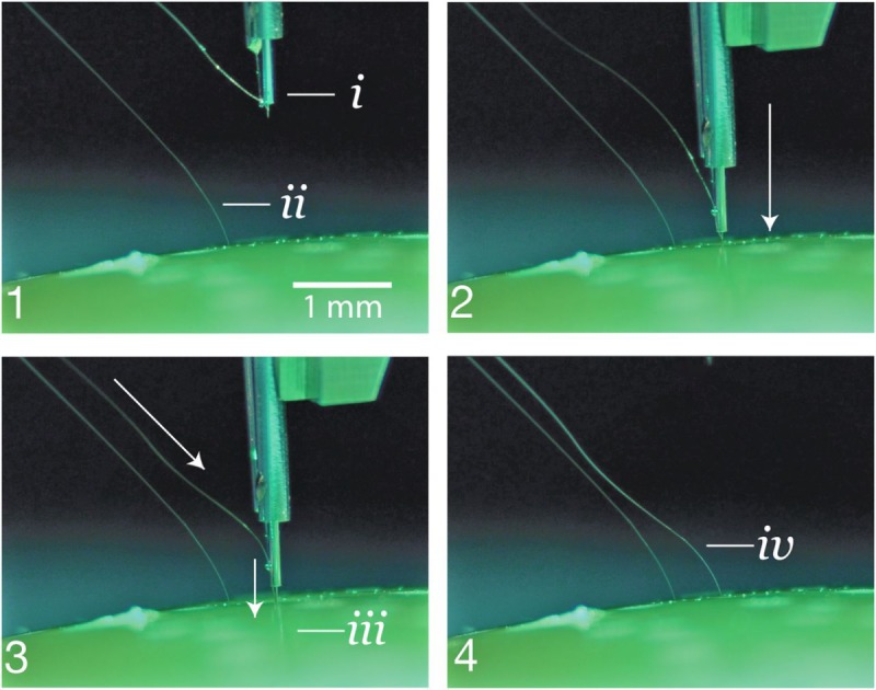
Insertion process into an agarose brain proxy. (1) The inserter approaches the brain proxy with a thread. (i) needle and cannula. (ii) Previously inserted thread. (2) Inserter touches down on the brain proxy surface. (3) Needle penetrates tissue proxy, advancing the thread to the desired depth. (iii) Inserting thread. (4) Inserter pulls away, leaving the thread behind in the tissue proxy. (iv) Inserted thread.
The needle is milled from 40-µm diameter tungsten-rhenium wire-stock electrochemically etched to 24-µm diameter along the inserted length (Figure 2A). The tip of the needle is designed both to hook onto insertion loops—for transporting and inserting individual threads—and to penetrate the meninges and brain tissue. The needle is driven by a linear motor, allowing variable insertion speeds and rapid retraction acceleration (up to 30,000 mm/s2) to encourage separation of the probe from the needle. The pincher is a 50-µm tungsten wire bent at the tip and driven both axially and rotationally (Figure 2B). It serves as a support for probes during transport and as a guide to ensure that threads are inserted along the needle path. Figure 3 shows a sequence of photographs of the insertion process into an agarose brain proxy.
The inserter head also holds an imaging stack (Figure 4E-G) used for guiding the needle into the thread loop, insertion targeting, live insertion viewing, and insertion verification. In addition, the inserter head contains six independent light modules, each capable of independently illuminating with 405 nm, 525 nm, and 650 nm or white light (Figure 4C). The 405-nm illumination excites fluorescence from polyimide and allows the optical stack and computer vision to reliably localize the 16×50 µm2 thread loop and execute submicron visual servoing to guide, while illuminated by 650 nm light, the needle through it. Stereoscopic cameras, software-based monocular extended depth-of-field calculations, and illumination with 525 nm light allow for precise estimation of the location of the cortical surface.
Figure 4.
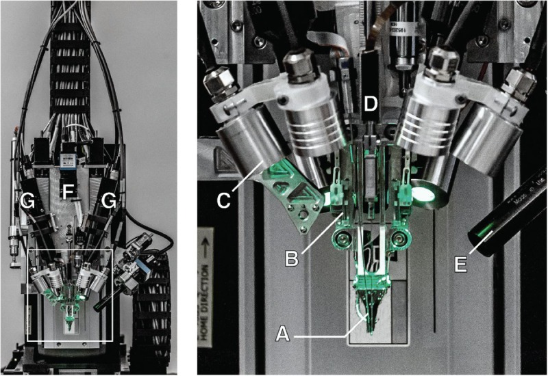
The robotic electrode inserter; enlarged view of the inserter-head shown in the inset. (A) Loaded needle pincher cartridge. (B) Low-force contact brain position sensor. (C) Light modules with multiple independent wavelengths. (D) Needle motor. (E) One of four cameras focused on the needle during insertion. (F) Camera with wide angle view of the surgical field. (G) Stereoscopic cameras.
The robot registers insertion sites to a common coordinate frame with landmarks on the skull, which, when combined with depth tracking, enables precise targeting of anatomically defined brain structures. An integrated custom software suite allows preselection of all insertion sites, enabling planning of insertion paths optimized to minimize tangling and strain on the threads. The planning feature highlights the ability to avoid vasculature during insertions, one of the key advantages of inserting electrodes individually. This is particularly important, since damage to the blood-brain barrier is thought to play a key role in the brain’s inflammatory response to foreign objects [33].
The robot features an autoinsertion mode, which can insert up to six threads (192 electrodes) per minute. Although the entire insertion procedure can be automated, the surgeon retains full control, and, if desired, can make manual microadjustments to the thread position before each insertion into the cortex. The neurosurgical robot is compatible with sterile shrouding and has features to facilitate successful and rapid insertions such as automatic sterile ultrasonic cleaning of the needle. The needle pincher cartridge (Figure 2C) is the portion of the inserter head that makes direct contact with brain tissue and is a consumable that can be replaced midsurgery in under a minute.
With this system, we have demonstrated an average of 87.1% (SD 12.6%) insertion success rate over 19 surgeries. In this study, precise manual adjustments were made to avoid microvasculature on the cortical surface, slowing total insertion time from the fastest possible time. Even with these adjustments, the total insertion time for this study averaged approximately 45 min for an approximate insertion rate of 29.6 electrodes per minute (Figure 5). Insertions were made in a 4×7 mm2 bilateral craniotomy with >300 µm spacing between threads to maximize cortical coverage. This demonstrates that robotic insertion of thin polymer electrodes is an efficient and scalable approach for recording from large numbers of neurons in anatomically defined brain regions.
Figure 5.
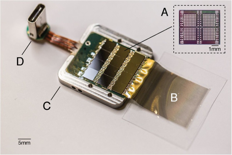
A packaged sensor device. (A) Individual neural processing application-specific integrated circuit capable of processing 256 channels of data. This particular packaged device contains 12 of these chips for a total of 3072 channels. (B) Polymer threads on parylene-c substrate. (C) Titanium enclosure (lid removed). (D) Digital USB-C connector for power and data.
Electronics
Chronic recording from thousands of electrode sites presents significant electronics and packaging challenges. The density of recording channels necessitates placing the signal amplification and digitization stack within the array assembly; otherwise, the cable and connector requirements would be prohibitive. This recording stack must amplify small neural signals (<10 µVRMS) while rejecting out-of-band noise, sample and digitize the amplified signals, and stream out the results for real-time processing—all using minimal power and size.
The electronics are built around our custom Neuralink application-specific integrated circuit (ASIC), which consists of 256 individually programmable amplifiers (“analog pixels”), on-chip analog-to-digital converters (ADCs), and peripheral control circuitry for serializing the digitized outputs. The analog pixel is highly configurable: The gains and filter properties can be calibrated to account for variability in signal quality due to process variations and the electrophysiological environment. The on-chip ADC samples at 19.3 kHz with 10-bit resolution. Each analog pixel consumes 5.2 µW, and the whole ASIC consumes approximately 6 mW, including the clock drivers. Performance of the Neuralink ASIC is summarized in Table 1, and a photograph of the fabricated device is shown in Figure 6A.
Table 1.
Neuralink application-specific integrated circuit.
| Variable | Value |
| Number of channels | 256 |
| Gain, dB | 42.9-59.4 |
| Bandwidth, kHz | 3-27 |
| Input-referred noise (3 Hz-10 kHz), µVRMS | 5.9 |
| Maximum differential input range, mVPP | 7.2 |
| Analog-to-digital converter resolution, bit | 10 |
| Analog pixel power, µW | 5.2 |
Figure 6.
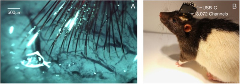
Thread implantation and packaging. (A) An example perioperative image showing the cortical surface with implanted threads and minimal bleeding. (B) Packaged sensor device (“System B”) chronically implanted in a rat.
The Neuralink ASIC forms the core of a modular recording platform that allows for easy replacement of constitutive parts for research and development purposes (Figure 6). In the systems discussed here, a number of ASICs are integrated into a standard PCB using flip-chip integration. Each system consists of a field-programmable gate array; real-time temperature, accelerometer, and magnetometer sensors; and a single USB-C connector for full-bandwidth data transfer. The systems are packaged in titanium cases that are coated with parylene-c, which serves as a moisture barrier to prevent fluid ingress and prolong functional lifetime.
We describe two such configurations that we have built—a 1536-channel recording system (“System A”) and a 3072-channel recording system (“System B”)—summarized in Table 2. System A employs the current-generation Neuralink ASIC, while System B uses an earlier revision with comparable functionality but poorer performance specifications.
Table 2.
Two recording system configurations.
| Variable | Value | |
| System A | System B | |
| Number of channels | 1536 | 3072 |
| Sampling rate, kHz | 19.3 | 18.6 |
| Total system power consumption, mW | 550 | 750 |
| Total system size, mm3 | 24.5×20×1.65 | 23×18.5×2 |
| Implant weight, g | 11 | 15 |
System B was designed to maximize channel density and is used for applications that demand extremely high channel count. In contrast, System A was designed to facilitate faster and more reliable manufacturing; it can be built five times faster than System B with better yields.
An Ethernet-connected base station converts the data streams from these systems into multicast 10 GB Ethernet user datagram protocol packets, allowing downstream users to process the data in a variety of ways, for example, visualizing the data in real time [34] or writing the data to disk. Each base station can connect to up to three implants simultaneously. These devices are further supported by a software ecosystem that allows for plug and play usability with zero configuration: Neural data begin streaming automatically when a cable is connected.
Electrophysiology
We have implanted both Systems A and B in male Long-Evans rats, as described in the section Robot. All animal procedures were performed in accordance with the National Research Council’s Guide for the Care and Use of Laboratory Animals and were approved by the Neuralink Institutional Animal Care and Use Committee. Electrophysiological recordings were taken as the animals freely explored an arena equipped with a commutated cable that permitted unrestricted movement. System A can record 1344 of 1536 channels simultaneously; the exact channel configuration can be arbitrarily specified at the time of recording; System B can record from all 3072 channels simultaneously. Digitized broadband signals were processed in real time to identify action potentials (spikes) using an online detection algorithm.
Spike detection requirements for real-time brain-machine interface are different from most conventional neurophysiology requirements. While most electrophysiologists spike-sort data offline and spend significant effort to reject false-positive spike events, brain-machine interface events must be detected in real time and spike detection parameters must maximize decoding efficacy. Using our custom online spike-detection software, we found that a permissive filter that allows an estimated false-positive rate of approximately 0.2 Hz performs better than setting stringent thresholds that may reject real spikes (data not shown).
Given these considerations, we set a threshold of >0.35 Hz to quantify the number of electrodes that recorded spiking units. Since we typically do not spike sort our data, we do not report multiple units per channel. Brain-machine interface decoders commonly operate without spike sorting with minimal loss of performance [35,36]. Moreover, recent results show that spike sorting is not necessary to accurately estimate neural population dynamics [37].
Data from a recent experiment using System A are shown in Figures 7 and 8. In this experiment, 40 of 44 attempted insertions were successful (90%) for a total of 1280 implanted electrodes, of which 1020 were recorded simultaneously. The broadband signals recorded from a representative thread show both local field and spiking activity (Figure 7). A sample output of the spike detection pipeline is shown in raster form in Figure 8. In this example, two overlapping recording configurations were used to record from all 1280 implanted channels. On this array, our spiking yield was 43.4% of the channels, with many spikes appearing on multiple neighboring channels, as has been observed in other high-density probes [16,17,21]. On other System A arrays, we observed a spiking yield of 45.60% (SD 0.03%) across 19 surgeries, with a maximum spiking yield of 70%.
Figure 7.
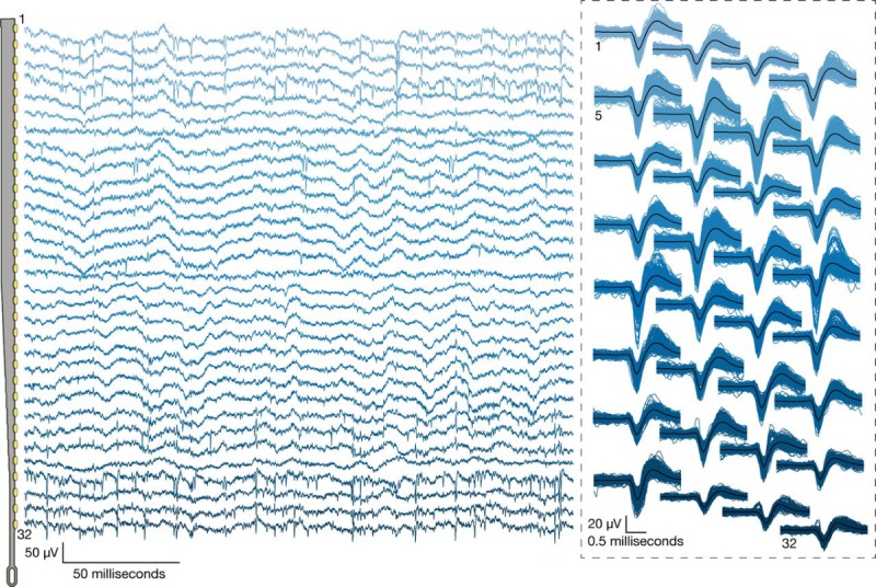
The broadband signals recorded from a representative thread. Left: Broadband neural signals (unfiltered) simultaneously acquired from a single thread (32 channels) implanted in rat cerebral cortex. Each channel (row) corresponds to an electrode site on the thread (schematic at left; sites spaced by 50 μm). Spikes and local field potentials are readily apparent. Right: Putative waveforms (unsorted); numbers indicate channel location on thread. Mean waveform is shown in black.
Figure 8.
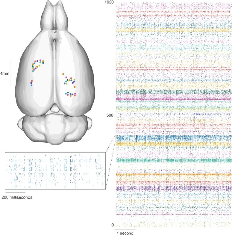
Our devices allow the recording of widespread neural activity distributed across multiple brain regions and cortical layers. Left: Thread insertion sites (colored circles) are indicated on the rendered rodent brain [38]. Right: Raster of 1020 simultaneously recorded channels, sorted per thread (color corresponds to insertion site). Inset: Enlarged raster of spikes from a single thread. This thread corresponds to the one shown in Figure 7.
Discussion
We have described a brain-machine interface with a high-channel count and single-spike resolution. It is based on flexible polymer probes, a robotic insertion system, and custom low-power electronics. This system serves two main purposes: It is a research platform for use in rodents and serves as a prototype for future human clinical implants. The ability to quickly iterate designs and testing in rodents allows for the rapid refinement of devices, manufacturing processes, and software. Because it is a research platform, the system uses a wired connection to maximize the bandwidth for raw data streaming. This is important for performance assessments and crucial for the development of signal processing and decoding algorithms. In contrast, the clinical devices that derive from this platform will be fully implantable, which requires hermetic packaging, and have on-board signal compression, reduced power consumption, wireless power transmission, and data telemetry through the skin without percutaneous leads.
Modulating neural activity will be an important part of next-generation clinical brain-machine interfaces [39], for example, to provide a sense of touch or proprioception to neuroprosthetic movement control [40,41]. Therefore, we designed the Neuralink ASIC to be capable of electrical stimulation on every channel, although we have not demonstrated these capabilities here.
This brain-machine interface system has several advantages over previous approaches. The size and composition of the thin-film probes are a better match for the material properties of brain tissue than commonly used silicon probes and may therefore exhibit enhanced biocompatibility [28,21]. In addition, the ability to choose where our probes are inserted, including into the subcortical structures, allows us to create custom array geometries for targeting specific brain regions while avoiding vasculature. This feature is significant for creating a high-performance brain-machine interface, as the distribution of electrodes can be customized depending on the task requirements. Lastly, the miniaturization and design of the Neuralink ASIC affords great flexibility in system design and supports very high channel counts within practical size and power constraints.
In principle, our approach to brain-machine interfaces is highly extensible and scalable. Here, we report simultaneous broadband recording from over 3000 inserted electrodes in a freely moving rat. In a larger brain, multiple devices with this architecture could be readily implanted, and we could therefore interface with many more neurons without extensive re-engineering. Further development of surgical robotics could allow us to accomplish this without dramatically increasing surgery time.
Although significant technological challenges must be addressed before a high-bandwidth device is suitable for clinical application, with such a device, it is plausible to imagine that a patient with spinal cord injury could dexterously control a digital mouse and keyboard. When combined with rapidly improving spinal stimulation techniques [42], in the future, this approach could conceivably restore motor function. High-bandwidth neural interfaces should enable a variety of novel therapeutic possibilities.
Acknowledgments
We would like to acknowledge the contributions of Lawrence Livermore National Laboratory (LLNL), Berkeley Marvell Nanofabrication Laboratory, Berkeley Wireless Research Center (BWRC), Stanford Nanofabrication Facility, and former and current Neuralink employees in the work described here. Thread manufacturing and high-density package assembly were performed in collaboration with LLNL (CRADA No. TC02267).
Abbreviations
- ADC
analog-to-digital converters
- ASIC
application-specific integrated circuit
- IrOx
iridium oxide
- PCB
printed circuit board
- PEDOT:PSS
poly-ethylenedioxythiophene doped with polystyrene sulfonate
Appendix
Video 1: A series of six insertions by the neurosurgical robot into an agarose brain proxy. Thread-capture by the needle occurs off-frame. The changes in background color are caused by illumination with different frequencies of light at different stages of the threading and insertion process. One thread was inserted before the start of the video.
Video 2: A 3D rendered view of thread arrangement (same data presented in Figure 8). Thread insertion is visualized in the same order as in the actual surgery, but time has been compressed for presentation. Thread size and insertion depth are representative. The stereotaxic coordinates of each insertion are represented on the dataset provided by Calabrese and coworkers [35].
Footnotes
Conflicts of Interest: Authors are affiliated with Neuralink.
References
- 1.Hochberg LR, Serruya MD, Friehs GM, Mukand JA, Saleh M, Caplan AH, Branner A, Chen D, Penn RD, Donoghue JP. Neuronal ensemble control of prosthetic devices by a human with tetraplegia. Nature. 2006 Jul 13;442(7099):164–71. doi: 10.1038/nature04970. [DOI] [PubMed] [Google Scholar]
- 2.Wang W, Collinger JL, Degenhart AD, Tyler-Kabara EC, Schwartz AB, Moran DW, Weber DJ, Wodlinger B, Vinjamuri RK, Ashmore RC, Kelly JW, Boninger ML. An electrocorticographic brain interface in an individual with tetraplegia. PLoS One. 2013;8(2):e55344. doi: 10.1371/journal.pone.0055344. http://dx.plos.org/10.1371/journal.pone.0055344. [DOI] [PMC free article] [PubMed] [Google Scholar]
- 3.Aflalo T, Kellis S, Klaes C, Lee B, Shi Y, Pejsa K, Shanfield K, Hayes-Jackson S, Aisen M, Heck C, Liu C, Andersen RA. Neurophysiology. Decoding motor imagery from the posterior parietal cortex of a tetraplegic human. Science. 2015 May 22;348(6237):906–10. doi: 10.1126/science.aaa5417. http://www.sciencemag.org/cgi/pmidlookup?view=long&pmid=25999506. [DOI] [PMC free article] [PubMed] [Google Scholar]
- 4.Hochberg LR, Bacher D, Jarosiewicz B, Masse NY, Simeral JD, Vogel J, Haddadin S, Liu J, Cash SS, van der Smagt P, Donoghue JP. Reach and grasp by people with tetraplegia using a neurally controlled robotic arm. Nature. 2012 May 16;485(7398):372–5. doi: 10.1038/nature11076. http://europepmc.org/abstract/MED/22596161. [DOI] [PMC free article] [PubMed] [Google Scholar]
- 5.Collinger JL, Wodlinger B, Downey JE, Wang W, Tyler-Kabara EC, Weber DJ, McMorland AJC, Velliste M, Boninger ML, Schwartz AB. High-performance neuroprosthetic control by an individual with tetraplegia. Lancet. 2013 Feb 16;381(9866):557–64. doi: 10.1016/S0140-6736(12)61816-9. http://europepmc.org/abstract/MED/23253623. [DOI] [PMC free article] [PubMed] [Google Scholar]
- 6.Anumanchipalli GK, Chartier J, Chang EF. Speech synthesis from neural decoding of spoken sentences. Nature. 2019 Apr;568(7753):493–498. doi: 10.1038/s41586-019-1119-1. [DOI] [PMC free article] [PubMed] [Google Scholar]
- 7.Buzsáki G, Anastassiou CA, Koch C. The origin of extracellular fields and currents--EEG, ECoG, LFP and spikes. Nat Rev Neurosci. 2012 May 18;13(6):407–20. doi: 10.1038/nrn3241. http://europepmc.org/abstract/MED/22595786. [DOI] [PMC free article] [PubMed] [Google Scholar]
- 8.Pesaran B, Vinck M, Einevoll GT, Sirota A, Fries P, Siegel M, Truccolo W, Schroeder CE, Srinivasan R. Investigating large-scale brain dynamics using field potential recordings: analysis and interpretation. Nat Neurosci. 2018 Jul;21(7):903–919. doi: 10.1038/s41593-018-0171-8. [DOI] [PMC free article] [PubMed] [Google Scholar]
- 9.Kaiju T, Doi K, Yokota M, Watanabe K, Inoue M, Ando H, Takahashi K, Yoshida F, Hirata M, Suzuki T. High spatiotemporal resolution ECoG recording of somatosensory evoked potentials with flexible micro-electrode arrays. Front Neural Circuits. 2017;11:20. doi: 10.3389/fncir.2017.00020. doi: 10.3389/fncir.2017.00020. [DOI] [PMC free article] [PubMed] [Google Scholar]
- 10.Yuste R. From the neuron doctrine to neural networks. Nat Rev Neurosci. 2015 Aug;16(8):487–97. doi: 10.1038/nrn3962. [DOI] [PubMed] [Google Scholar]
- 11.Hong G, Lieber CM. Novel electrode technologies for neural recordings. Nat Rev Neurosci. 2019 Jun;20(6):330–345. doi: 10.1038/s41583-019-0140-6. http://europepmc.org/abstract/MED/30833706. [DOI] [PMC free article] [PubMed] [Google Scholar]
- 12.Maynard EM, Nordhausen CT, Normann RA. The Utah intracortical Electrode Array: a recording structure for potential brain-computer interfaces. Electroencephalogr Clin Neurophysiol. 1997 Mar;102(3):228–39. doi: 10.1016/s0013-4694(96)95176-0. [DOI] [PubMed] [Google Scholar]
- 13.Nicolelis MAL, Dimitrov D, Carmena JM, Crist R, Lehew G, Kralik JD, Wise SP. Chronic, multisite, multielectrode recordings in macaque monkeys. Proceedings of the National Academy of Sciences. 2003 Sep 05;100(19):11041–11046. doi: 10.1073/pnas.1934665100. https://www.pnas.org/content/100/19/11041.full.pdf. [DOI] [PMC free article] [PubMed] [Google Scholar]
- 14.Wise K, Sodagar A, Yao Y, Gulari M, Perlin G, Najafi K. Microelectrodes, microelectronics, and implantable neural microsystems. Proceedings of the IEEE. 2008 Jul;96(7):1184–1202. doi: 10.1109/jproc.2008.922564. [DOI] [Google Scholar]
- 15.Dotson NM, Hoffman SJ, Goodell B, Gray CM. A large-scale semi-chronic microdrive recording system for non-human primates. Neuron. 2017 Nov 15;96(4):769–782.e2. doi: 10.1016/j.neuron.2017.09.050. https://linkinghub.elsevier.com/retrieve/pii/S0896-6273(17)30919-4. [DOI] [PubMed] [Google Scholar]
- 16.Jun JJ, Steinmetz NA, Siegle JH, Denman DJ, Bauza M, Barbarits B, Lee AK, Anastassiou CA, Andrei A, Aydın Ç, Barbic M, Blanche TJ, Bonin V, Couto J, Dutta B, Gratiy SL, Gutnisky DA, Häusser M, Karsh B, Ledochowitsch P, Lopez CM, Mitelut C, Musa S, Okun M, Pachitariu M, Putzeys J, Rich PD, Rossant C, Sun W, Svoboda K, Carandini M, Harris KD, Koch C, O'Keefe J, Harris TD. Fully integrated silicon probes for high-density recording of neural activity. Nature. 2017 Nov 08;551(7679):232–236. doi: 10.1038/nature24636. http://europepmc.org/abstract/MED/29120427. [DOI] [PMC free article] [PubMed] [Google Scholar]
- 17.Angotzi GN, Boi F, Lecomte A, Miele E, Malerba M, Zucca S, Casile A, Berdondini L. SiNAPS: An implantable active pixel sensor CMOS-probe for simultaneous large-scale neural recordings. Biosens Bioelectron. 2019 Feb 01;126:355–364. doi: 10.1016/j.bios.2018.10.032. https://linkinghub.elsevier.com/retrieve/pii/S0956-5663(18)30827-3. [DOI] [PubMed] [Google Scholar]
- 18.Deku F, Cohen Y, Joshi-Imre A, Kanneganti A, Gardner TJ, Cogan SF. Amorphous silicon carbide ultramicroelectrode arrays for neural stimulation and recording. J Neural Eng. 2018 Feb;15(1):016007. doi: 10.1088/1741-2552/aa8f8b. http://europepmc.org/abstract/MED/28952963. [DOI] [PMC free article] [PubMed] [Google Scholar]
- 19.Lecomte A, Descamps E, Bergaud C. A review on mechanical considerations for chronically-implanted neural probes. J Neural Eng. 2018 Jun;15(3):031001. doi: 10.1088/1741-2552/aa8b4f. [DOI] [PubMed] [Google Scholar]
- 20.Khodagholy D, Gelinas JN, Thesen T, Doyle W, Devinsky O, Malliaras GG, Buzsáki G. NeuroGrid: recording action potentials from the surface of the brain. Nat Neurosci. 2014 Dec 22;18(2):310–315. doi: 10.1038/nn.3905. [DOI] [PMC free article] [PubMed] [Google Scholar]
- 21.Chung JE, Joo HR, Fan JL, Liu DF, Barnett AH, Chen S, Geaghan-Breiner C, Karlsson MP, Karlsson M, Lee KY, Liang H, Magland JF, Pebbles JA, Tooker AC, Greengard LF, Tolosa VM, Frank LM. High-density, long-lasting, and multi-region electrophysiological recordings using polymer electrode arrays. Neuron. 2019 Jan 02;101(1):21–31.e5. doi: 10.1016/j.neuron.2018.11.002. [DOI] [PMC free article] [PubMed] [Google Scholar]
- 22.Chorover SL, Deluca A. A sweet new multiple electrode for chronic single unit recording in moving animals. Physiology & Behavior. 1972 Oct;9(4):671–674. doi: 10.1016/0031-9384(72)90030-3. [DOI] [PubMed] [Google Scholar]
- 23.Liu J, Fu T, Cheng Z, Hong G, Zhou T, Jin L, Duvvuri M, Jiang Z, Kruskal P, Xie C, Suo Z, Fang Y, Lieber CM. Syringe-injectable electronics. Nature Nanotech. 2015 Jun 8;10(7):629–636. doi: 10.1038/nnano.2015.115. [DOI] [PMC free article] [PubMed] [Google Scholar]
- 24.Fu T, Hong G, Zhou T, Schuhmann TG, Viveros RD, Lieber CM. Stable long-term chronic brain mapping at the single-neuron level. Nat Methods. 2016 Oct;13(10):875–82. doi: 10.1038/nmeth.3969. [DOI] [PubMed] [Google Scholar]
- 25.Vitale F, Vercosa DG, Rodriguez AV, Pamulapati SS, Seibt F, Lewis E, Yan JS, Badhiwala K, Adnan M, Royer-Carfagni G, Beierlein M, Kemere C, Pasquali M, Robinson JT. Fluidic microactuation of flexible electrodes for neural recording. Nano Lett. 2018 Jan 10;18(1):326–335. doi: 10.1021/acs.nanolett.7b04184. doi: 10.1021/acs.nanolett.7b04184. [DOI] [PMC free article] [PubMed] [Google Scholar]
- 26.Luan L, Wei X, Zhao Z, Siegel JJ, Potnis O, Tuppen CA, Lin S, Kazmi S, Fowler RA, Holloway S, Dunn AK, Chitwood RA, Xie C. Ultraflexible nanoelectronic probes form reliable, glial scar-free neural integration. Sci Adv. 2017 Feb;3(2):e1601966. doi: 10.1126/sciadv.1601966. http://europepmc.org/abstract/MED/28246640. [DOI] [PMC free article] [PubMed] [Google Scholar]
- 27.Marc D. BioRxiv. 2018. [2019-09-11]. NeuroRoots, a bio-inspired, seamless brain machine interface device for long-term recording https://www.biorxiv.org/content/biorxiv/early/2018/11/04/460949.full.pdf.
- 28.Timothy LH. BioRxiv. 2019. [2019-09-11]. The “sewing machine” for minimally invasive neural recording https://www.biorxiv.org/content/biorxiv/early/2019/03/14/578542.full.pdf.
- 29.Ludwig KA, Uram JD, Yang J, Martin DC, Kipke DR. Chronic neural recordings using silicon microelectrode arrays electrochemically deposited with a poly(3,4-ethylenedioxythiophene) (PEDOT) film. J Neural Eng. 2006 Mar;3(1):59–70. doi: 10.1088/1741-2560/3/1/007. [DOI] [PubMed] [Google Scholar]
- 30.Wilks SJ, Richardson-Burns SM, Hendricks JL, Martin DC, Otto KJ. Poly(3,4-ethylenedioxythiophene) as a micro-neural interface material for electrostimulation. Front Neuroeng. 2009;2:7. doi: 10.3389/neuro.16.007.2009. doi: 10.3389/neuro.16.007.2009. [DOI] [PMC free article] [PubMed] [Google Scholar]
- 31.Klein JD, Clauson SL, Cogan SF. Morphology and charge capacity of sputtered iridium oxide films. Journal of Vacuum Science & Technology A: Vacuum, Surfaces, and Films. 1989 Sep;7(5):3043–3047. doi: 10.1116/1.576313. [DOI] [Google Scholar]
- 32.Cogan SF, Plante TD, Ehrlich J. Sputtered Iridium Oxide Films (SIROFs) for Low-Impedance Neural Stimulation and Recording Electrodes. The 26th Annual International Conference of the IEEE Engineering in Medicine and Biology Society; 2004; San Francisco, USA. 2004. [DOI] [PMC free article] [PubMed] [Google Scholar]
- 33.Saxena T, Karumbaiah L, Gaupp EA, Patkar R, Patil K, Betancur M, Stanley GB, Bellamkonda RV. The impact of chronic blood-brain barrier breach on intracortical electrode function. Biomaterials. 2013 Jul;34(20):4703–13. doi: 10.1016/j.biomaterials.2013.03.007. [DOI] [PubMed] [Google Scholar]
- 34.Siegle JH, López AC, Patel YA, Abramov K, Ohayon S, Voigts J. Open Ephys: an open-source, plugin-based platform for multichannel electrophysiology. J Neural Eng. 2017 Aug;14(4):045003. doi: 10.1088/1741-2552/aa5eea. [DOI] [PubMed] [Google Scholar]
- 35.Todorova S, Sadtler P, Batista A, Chase S, Ventura V. To sort or not to sort: the impact of spike-sorting on neural decoding performance. J Neural Eng. 2014 Oct;11(5):056005. doi: 10.1088/1741-2560/11/5/056005. http://europepmc.org/abstract/MED/25082508. [DOI] [PMC free article] [PubMed] [Google Scholar]
- 36.Christie BP, Tat DM, Irwin ZT, Gilja V, Nuyujukian P, Foster JD, Ryu SI, Shenoy KV, Thompson DE, Chestek CA. Comparison of spike sorting and thresholding of voltage waveforms for intracortical brain–machine interface performance. J Neural Eng. 2014 Dec 11;12(1):016009. doi: 10.1088/1741-2560/12/1/016009. [DOI] [PMC free article] [PubMed] [Google Scholar]
- 37.Trautmann Eric M, Stavisky Sergey D, Lahiri Subhaneil, Ames Katherine C, Kaufman Matthew T, O'Shea Daniel J, Vyas Saurabh, Sun Xulu, Ryu Stephen I, Ganguli Surya, Shenoy Krishna V. Accurate estimation of neural population dynamics without spike sorting. Neuron. 2019 Jul 17;103(2):292–308.e4. doi: 10.1016/j.neuron.2019.05.003. [DOI] [PMC free article] [PubMed] [Google Scholar]
- 38.Calabrese E, Badea A, Watson C, Johnson GA. A quantitative magnetic resonance histology atlas of postnatal rat brain development with regional estimates of growth and variability. Neuroimage. 2013 May 01;71:196–206. doi: 10.1016/j.neuroimage.2013.01.017. http://europepmc.org/abstract/MED/23353030. [DOI] [PMC free article] [PubMed] [Google Scholar]
- 39.Zhou A, Santacruz SR, Johnson BC, Alexandrov G, Moin A, Burghardt FL, Rabaey JM, Carmena JM, Muller R. A wireless and artefact-free 128-channel neuromodulation device for closed-loop stimulation and recording in non-human primates. Nat Biomed Eng. 2018 Dec 31;3(1):15–26. doi: 10.1038/s41551-018-0323-x. [DOI] [PubMed] [Google Scholar]
- 40.O’Doherty JE, Lebedev MA, Ifft PJ, Zhuang KZ, Shokur S, Bleuler H, Nicolelis MAL. Active tactile exploration using a brain–machine–brain interface. Nature. 2011 Oct 5;479(7372):228–231. doi: 10.1038/nature10489. [DOI] [PMC free article] [PubMed] [Google Scholar]
- 41.Sharlene NF. BioRxiv. 2019. [2019-09-11]. Restored tactile sensation improves neuroprosthetic arm control? https://www.biorxiv.org/content/biorxiv/early/2019/05/31/653428.full.pdf.
- 42.Wagner FB, Mignardot J, Le Goff-Mignardot CG, Demesmaeker R, Komi S, Capogrosso M, Rowald A, Seáñez I, Caban M, Pirondini E, Vat M, McCracken LA, Heimgartner R, Fodor I, Watrin A, Seguin P, Paoles E, Van Den Keybus K, Eberle G, Schurch B, Pralong E, Becce F, Prior J, Buse N, Buschman R, Neufeld E, Kuster N, Carda S, von Zitzewitz J, Delattre V, Denison T, Lambert H, Minassian K, Bloch J, Courtine G. Targeted neurotechnology restores walking in humans with spinal cord injury. Nature. 2018 Oct 31;563(7729):65–71. doi: 10.1038/s41586-018-0649-2. [DOI] [PubMed] [Google Scholar]
Associated Data
This section collects any data citations, data availability statements, or supplementary materials included in this article.
Supplementary Materials
Video 1: A series of six insertions by the neurosurgical robot into an agarose brain proxy. Thread-capture by the needle occurs off-frame. The changes in background color are caused by illumination with different frequencies of light at different stages of the threading and insertion process. One thread was inserted before the start of the video.
Video 2: A 3D rendered view of thread arrangement (same data presented in Figure 8). Thread insertion is visualized in the same order as in the actual surgery, but time has been compressed for presentation. Thread size and insertion depth are representative. The stereotaxic coordinates of each insertion are represented on the dataset provided by Calabrese and coworkers [35].