Abstract
Total body irradiation (TBI) is a complex treatment technique, which has been slow to transition to a three‐dimensional (3D) planning approach. There is limited literature available providing a detailed description on methods to plan TBI on a 3D planning system. 3D planning using the modulated arc TBI (MATBI) technique is a complex process involving a significant number of quality assurance processes and scripts, due to more than 40 treatment beams and two patient positions. This article will focus on the workflow and technical planning aspects of our institution’s MATBI technique and identify reasons for modifications made to the developing institution’s original MATBI approach. Included is a description of specific simulation equipment, detailed explanation of the four‐stage computing process including the role of scripting to standardise and streamline what is otherwise a complex number of steps. The information provided is specific to one centre’s approach but shows the fundamental planning process and demonstrates a streamlined method, which can be adapted to other planning systems. Overall, the ability to accurately represent the TBI technique in 3D on a planning system will be shown.
Keywords: total body irradiation, modulated arc therapy, paediatric cancers
This article will focus on the workflow and technical planning aspects of our institution’s MATBI technique and identify reasons for modifications made to the developing institution’s original MATBI approach. Included is a description of specific simulation equipment, detailed explanation of the four‐stage computing process including the role of scripting to standardise and streamline what is otherwise a complex number of steps. Alterations to the original technique will be discussed.
Introduction
Total body irradiation (TBI) is a radiation therapy treatment that delivers a dose of radiation to the whole body and is used in conjunction with chemotherapy to prepare the body for a bone marrow transplant. Centres are increasingly transitioning to a 3D planning technique for TBI allowing more detailed information to be calculated for organs at risk.1 In late 2014, Radiation Oncology Princess Alexandra Hospital – Raymond Terrace (ROPART), became the new primary provider of paediatric radiation therapy services in Queensland and was required to develop a treatment protocol for TBI. The technique selected was the MATBI, which was developed by the Department of Radiation Oncology, University of California San Francisco described by Kirby et al. and Held et al.2, 3 This technique had not been previously used in Australia. For treatment, the patient is positioned on a custom‐made couch placed on the floor directly under the treatment beam, at an extended distance of approximately 2 metres. The patient is treated in a supine and prone position, with a series of static open field beams in an arc formation. Lung dose is compensated using lead shields positioned close to the patient’s surface, and a Perspex spoiler is used to increase skin dose. Thus far, 25 patients between the ages of 2 and 18 years have completed a course of treatment. As a detailed description of the treatment technique and initial implementation has been published separately by Pemberton et al., this article will focus on the planning workflow.4 The technical planning aspects of the MATBI technique and the alterations made to the original MATBI approach outlined by Kirby et al.2 and Held et al.3 will be detailed. The streamlined process and robust quality assurance (QA) procedures will be shown, with the ability to accurately represent MATBI on a planning system being demonstrated. An exemption from institutional ethics approval was granted (reference number HREC/16/QPAH/718) for this review of our department’s MATBI technique.
Simulation
Due to limited literature relating to the MATBI technique, there was uncertainty surrounding consistency of lung shape and size between the prone and supine positioning. At the time of implementation in our department, it was decided that the acquisition of two CT scans, a full body CT in the prone position and a supine scan of the chest region, would be required. The full body prone CT dataset is the primary dataset used for dosimetry calculations, while the chest supine scan is only required to design lung compensators for the anterior fields. Prior to implementation in our department, testing was conducted using the supine position as per Kirby et al.2 It was determined that some patients may require kidney as well as lung compensators. Due to the kidneys being a posterior organ, only posterior compensators would be used. The approach was adjusted to a full body prone planning scan due to more accuracy with respect to the kidney compensator design.
To ensure positioning is replicated between the prone and supine scans, when the patient is prone, their shoulders, buttocks and heels need to be horizontal to the treatment couch as they are the points of contact when supine (Fig. 1). Large vacbags are utilised for all patients for the supine and prone positioning, generally encompassing the shoulders to the knees depending on patient size. A variety of foam supports are placed under the prone vacbag to raise the torso and legs of the patient to correctly align the body in the superior/inferior direction (Fig. 1). Arms are positioned approximately mid‐separation for both positions, with the position supported by the foam blocks and vacbag (Fig. 1). Numerous positional measurements are recorded to reproduce the patient’s position between the prone and supine positions.
Figure 1.
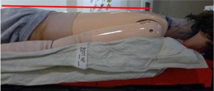
Phantom in prone treatment position.
Patients can select their preferred head position of straight or turned to the left. It was found that the preference for head position varied between individuals. Patients requiring general anaesthetic are positioned with their head turned to the left to allow enhanced visualisation of the patient on CCTV during treatment.
Scans are completed using a Siemens Somatom Definition AS scanner, with a setting of 120kVp, 3 mm slice, 1.4 pitch, on a B31s medium smooth reconstruction kernel and a 600‐mm field of view. The scan length is limited to 180 cm.
Dosimetry
The treatment planning system used at ROPART is Pinnacle3, Version 14 and 16 (Philips Healthcare, Fitchburg, WI, USA). There are several unique challenges to accurately representing MATBI on a treatment planning system. The complexity of two patient positions, but the requirement of a single planning dataset, led to the development of specific scripts and the detailed QA process. An overview of the planning procedure and QA processes can be seen in Figure 2.
Figure 2.
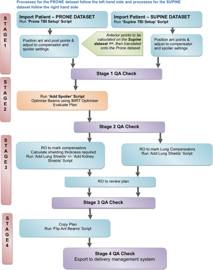
Flowchart of Computing Process. QA – quality assurance; RO – Radiation Oncologist.
As noted previously, the full body prone scan is used as the primary data for dose calculations as well as being used to design posterior field kidney and lung compensators. The supine scan is only utilised to;
Define spoiler and compensator tray position for the supine position.
Define the lung compensator shapes.
Produce a set up beam for imaging for the supine position.
Due to the large number of equipment positioning and dose points of interest (POI), beams and regions of interest, the development of scripts resulted in significant time savings for this technique. Table 1 shows an overview of the scripts used throughout the planning process. There are four stages to the planning process (Fig. 2). These are;
Plan set up – POI + beams
Optimised plan with no lung compensation
Optimised plan including lung compensation (true dosimetric representation on the planning system)
Anterior beams flipped to deliverable beams for supine treatment (used for beam delivery and exported to the treatment delivery programme)
Table 1.
Scripts developed for MATBI dosimetry.
| Script | Purpose |
|---|---|
| Prone TBI Set up | Basic plan set up. Adds treatment beams, POI, names for ROI, prescription, dose grid and IMRT objective |
| Supine TBI Set up | Basic plan set up. Adds setup beams, POI, names for ROI, prescription and dose grid |
| Add spoiler | Creates spoiler as a region of interest and removes CT couch |
| Add Lung Shields | Creates lung compensators as a ROI. Planner inputs thickness and density of compensators |
| Add Kidney Shields | Creates posterior kidney compensators as a ROI. Planner inputs thickness and density of compensators |
| Flip Ant Beams | Converts the prone anterior beams to deliverable beams when patient is positioned supine |
| Show Lung Shield Info | Shows data on thickness and density of lung compensator ROI for QA purposes |
| Show Kidney Shield Info | Shows data on thickness and density of kidney compensator ROI for QA purposes |
POI‐ points of interest; ROI‐ regions of interest; QA‐ quality assurance.
Each of the four planning stages will be discussed individually.
In comparison with a standard single QA check for routine techniques, four QA checks are required for MATBI (Fig. 2). Each QA check performs a manual assessment of the planning steps necessary to complete each stage. This approach was preferred due to the use of two patient positions and the relationship between accurate POI placement and corresponding equipment limitations. It ensures a deliverable plan prior to the Radiation Oncologist’s review and the early detection of errors enhances overall efficiency in the planning process.
Stage 1: Plan set up
The ‘TBI Setup’ scripts are used for base plan set up. The script parameters are adjusted to suit the patient‐specific constraints. Equipment positioning and settings rely on the accurate positioning of POI in Pinnacle3, such as the height of the compensators, spoiler and couch settings. Figure 3 shows an example of equipment positioning points used. These points are used to indicate the physical position of the compensator bridge and the spoiler. An excel program has been developed to guide staff in appropriate selection of equipment settings (Fig. 4). Individual patient data are input and the programme calculates suggested equipment settings and POI location. Individual patient factors must also be considered, such as chest separation. In most cases, the prescription is 12Gy in 6#. The Stage 1 QA Check involves a manual calculation of POI locations to confirm accuracy of the programme.
Figure 3.
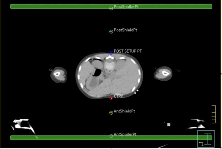
Example of equipment positioning points. PostSpoiler Pt and AntSpoilerPt – indicates the physical position of the spoiler for the prone and supine position. A minimum of 10 cm from the patient’s surface. PostShieldPt and AntShieldPt – indicate the physical position of the compensators for the prone and supine position. A minimum of 4 cm from the patient’s surface. CTRP – CT reference point. POST SETUP PT – posterior set up point. Green region of interest‐spoiler.
Figure 4.
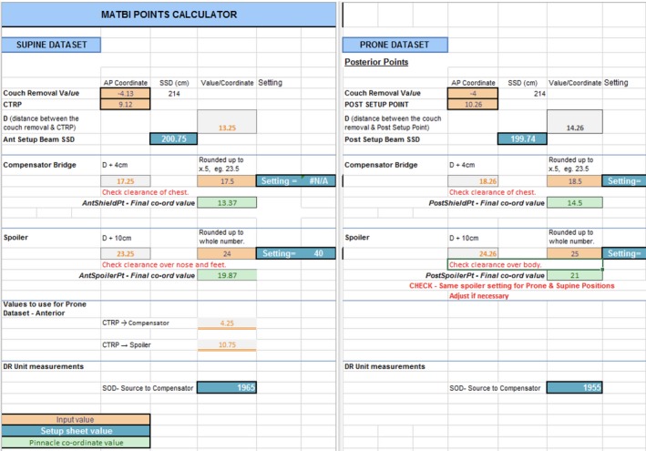
Points calculator excel program.
Standard beam parameters are static 6MV beams placed every 5 degrees, with approximately 40 beams in total. Initially, all beams are 40x40cm in size and no multi‐leaf collimation is used. The dose rate is lowered to 60MU/min for any fields treating lung tissue to reduce the risk of pulmonary complications and 300MU/min for all other fields.2 The prone and supine beam angles are offset to eliminate opposing beams, creating a more uniform dose distribution across the length of the patient. The patient is positioned at approximately 2 metres SSD.
Stage 2: Plan optimisation (no lung compensation)
A beam spoiler is added to the plan prior to beam optimisation to increase skin dose. The ‘add spoiler’ script adds the anterior and posterior spoiler as a region of interest and overrides the CT couch to a density of zero. The spoiler region of interest is 1cm thick and has a density of 1g/cm3. The spoiler is positioned approximately 10cm from the patients’ surface providing sufficient distance for compensator positioning, but close enough not to lose the spoiler effect (Fig. 3). Should it be required that the spoiler can be positioned between 4cm and 15cm from the surface of the patient without compromising the spoiler effect. Physics measurements confirmed not to exceed a distance of 16cm as the spoiler effect begins to rapidly degrade with increasing distance from skin due to the repeated build‐up effect.
Beams are optimised using the IMRT beam weighting optimiser, which modulates the monitor units of the beams to optimise body dose homogeneity. An initial objective of a uniform dose to ‘body‐lungs’ (body minus lungs) is used. Plans are evaluated for uniformity using the standard TBI dose parameters of ± 10% of the reference dose, with a minimum of 95% coverage of bone marrow.5, 6 To overcome high‐dose regions in areas of reduced separation, the field width of 1 to 4 beams is adjusted to exclude the thin patient regions after the MU has been determined by the IMRT optimiser. This is often needed on the arms and lateral aspects of the thighs. Figure 5 shows an example of field width adjustment. Figure 5a shows the dose distribution prior to the adjustment, with unacceptable high‐dose regions throughout the arms. In Figure 5b, the dose distribution is more homogenous with acceptable high‐dose regions. Beams are only adjusted for the prone position as this is the primary dataset eliminating potential uncertainty in limb positioning when the patient is supine. Comparatively, although high doses are acknowledged in the arms and fingers (Held et al.3), MLC use or field width adjustments were not used in the technique described by Kirby et al.2, 3
Figure 5.
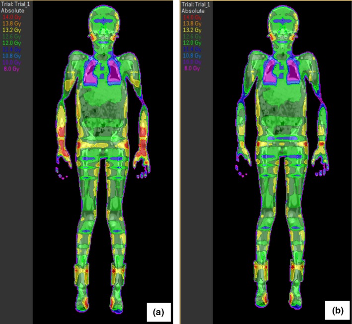
(a) Coronal view of dose distribution of stage 2 prior to jaw adjustment. (b) Coronal view of dose distribution of stage 2 after jaw adjustment.
Stage 3: Lung compensation
Stage 3 involves the addition of compensators. Median lung doses over 10‐12Gy have been associated with increased risk of interstitial pneumonitis, so lead compensators are utilised to reduce the mean lung dose to below 10Gy.7 Kidney compensation may also be requested. Compensators are positioned as close as possible to the skin surface, usually approximately 4‐5cm to allow for breathing.
To create the compensators in Pinnacle3, the RO outlines the required shape on a set up field. Separate compensators are marked on the prone and supine scan to account for any variation in lung and heart position. The ‘compensator’ scripts then use this shape to create regions of interest and prompt the planner to enter the thickness and density required for the contours. As the data point, the set up fields are attached to are in the same location anterior/posterior as the compensator data point no magnification factor is required. The lead sheets used to construct the compensators are 3‐mm thick and have a density of 11.2 g/cm3, but the CT resolution is 1.27‐mm sized voxels. The CT is acquired with a 600‐cm field of view to ensure the voxel size is not altered in Pinnacle3. As 3mm does not divide evenly into 1.27‐mm voxels, the actual density of 11.2 g/cm3 cannot be used. As a result, thickness and density override values are input into Pinnacle3 such that the calculation reflects the actual attenuation from the lead compensator. The compensator values input can be seen in Table 2. Beams are recalculated with the compensators, but not reoptimised. The final plan from stage 3 is a true dosimetric representation of MATBI on a planning system, and an example can be seen in Figure 6. This method was preferred to performing a megavoltage cone beam CT of the compensators and fusing the images into Pinnacle3 as reported by Kirby et al.2
Table 2.
Compensator values for script.
| Number of sheets | 1 | 2 | 3 | 4 | 6 |
|---|---|---|---|---|---|
| Approximate attenuation (%) | 10 | 20 | 30 | 40 | 50 |
| Thickness for Pinnacle3 (cm)a | 0.28 | 0.56 | 0.84 | 1.12 | 1.68 |
| Density of Pinnacle3 (g/cm3)a | 10.2 | 10.4 | 12.5 | 12 | 12.5 |
Actual density of lead = 11.2 g/cm3 and lead sheet thickness = 0.28cm.
Figure 6.
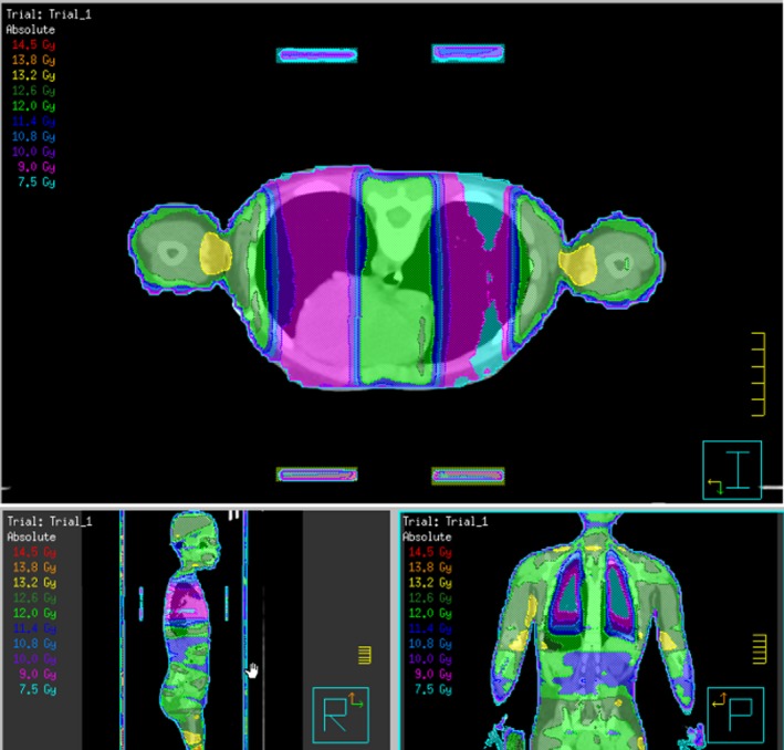
Example of final plan dosimetry.
Stage 4: Deliverable plan
As seen in Figure 2, the plan is copied to create deliverable beams that are exported to the treatment delivery programme. The anterior beams, which would standardly be treated through the couch are not deliverable as the patient need to be positioned on the floor to achieve the extended SSD. Therefore, the ‘flip ant beams’ script is run, to convert the anterior beams calculated in stage 3 to deliverable angles with the patient in a supine position, as demonstrated in Figure 7. Essentially, the plan is copied and the anterior fields planned on the prone CT scan are opposed to the angles required to replicate beam positioning in the patient when they are lying supine for treatment. The conversion of each field needs to be checked by the planner and checking radiation therapist, but the scripts allow greater efficiency in the conversion of approximately 20 beam angles. As the field width of beams to reduce dose to the arms are only adjusted in the prone position, no alterations of other supine field parameters are required.
Figure 7.
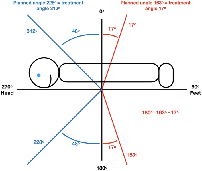
Example stage 4 showing flipping anterior beams to gantry angles above the horizontal to achieve deliverable treatment angles.
Summary
This report has summarised the planning process for MATBI in our institution. The main differences between our technique and that reported by Kirby et al.’s have been discussed.2 This includes that a full body prone dataset is used to perform dosimetric calculations and compensators are created as regions of interest. Field widths are also adjusted to compensate for high‐dose regions. Although our technique involves numerous steps, scripting has been used to simplify and improve efficiency and accuracy in planning these cases. The first three QA checks were integrated into the planning process to confirm vital POI in the process before the next step is undertaken with the final QA to confirm the plan is accurate and deliverable. It has been demonstrated that a true dosimetric representation of MATBI on a planning system can be achieved. Although the processes described were specific to the Pinnacle3 planning system, it is anticipated that the overall streamlined process is transferable to other planning systems.
J Med Radiat Sci 66(2019) 284–291
References
- 1. Peters M, Taylor B, Turner E. An Evidence‐based review of total body irradiation. J Med Imaging Radiat Sci 2015; 46: 442–9. [DOI] [PubMed] [Google Scholar]
- 2. Kirby N, Held M, Morin O, Fogh S, Pouliot J. Inverse‐planned modulated‐arc total‐body irradiation. Med Phys 2012; 39: 2761–4. [DOI] [PubMed] [Google Scholar]
- 3. Held M, Kirby N, Morin O, Pouliot J. Dosimetric aspects of inverse‐planned modulated‐arc total‐body irradiation. Med Phys 2012; 39: 5263–71. [DOI] [PubMed] [Google Scholar]
- 4. Pemberton M, Brady C, Taylor B, et al. Modification of a modulated arc total body irradiation technique: Implementation and first clinical experience for paediatric patients. J Med Radiat Sci 2018; 65: 291–299. [DOI] [PMC free article] [PubMed] [Google Scholar]
- 5. Quast U. Whole body radiotherapy: A TBI‐guideline. J Med Phys 2006; 31: 5. [DOI] [PMC free article] [PubMed] [Google Scholar]
- 6. Van Dyk J, Galvin J, Glasgow G, Podgoršak EB, Committee ART. The physical aspects of total and half body photon irradiation: a report of Task Group 29, Radiation therapy committee association of physicists in medicine: American association of of physicists in medicine; 1986.
- 7. Marks LB, Bentzen SM, Deasy JO, et al. Radiation dose‐volume effects in the lung. Int J Radiat Oncol Biol Phys 2010; 76(Suppl): S70–6. [DOI] [PMC free article] [PubMed] [Google Scholar]


