Abstract
Atrial tachycardia is defined as a regular atrial activation from atrial areas with centrifugal spread, caused by enhanced automaticity, triggered activity or microreentry. New ECG classification differentiates between focal and macroreentrant atrial tachycardia. Macroreentrant atrial tachycardias include typical atrial flutter and other well characterized macroreentrant circuits in right and left atrium. Typical atrial flutter has been described as counterclockwise reentry within right atrial and it presents a characteristic ECG “sawtooth” pattern on the inferior leads. The foci responsible for focal atrial tachycardia do not occur randomly throughout the atria but tend to cluster at characteristic anatomical locations. The surface ECG is a very helpful tool in directing mapping to particular areas of interest. Atrial tachycardia should be differentiated from other supraventricular tachycardias. We propose a diagnostic algorithm in order to help the physician to discriminate among those. Holter analysis could offer further details to differentiate between atrial tachycardia and another supraventricular tachycardia. However, if the diagnosis is uncertain, it is possible to utilize vagal maneuvers or adenosine administration. In conclusion, in spite of well–known limits, a good interpretation of ECG is very important and it could help the physician to manage and to treat correctly patients with atrial tachycardia.
Keywords: ECG, atrial tachycardia, atrial flutter, supraventricular tachycardia, diagnostic algorithm
Atrial tachycardia (AT) is defined as a regular atrial activation from atrial areas with centrifugal spread, caused by enhanced automaticity, triggered activity, or microreentry.1 Electrophysiological studies showed that electrocardiogram (ECG) is not able to properly explain all the AT mechanisms.2 Nevertheless, current classification establishes precise criteria to define these arrhythmias in spite of known ECG limits.2 Moreover, localization of AT and differential diagnosis between AT and other supraventricular tachycardia (SVT) may be very hard and therefore the good knowledge of ECG is fundamental to diagnose and to treat correctly these rhythm disorders.
In this article, we showed two ECG reports that represented a diagnostic challenge in the clinical practice. Afterward, we conducted a review about electrocardiographic diagnosis of AT (classification, localization, and differential diagnosis with other SVTs) in order to help the physician to better manage these arrhythmias.
CASE SERIES
Case Report 1
An 80‐year‐old male patient, affected by metabolic syndrome, coronary artery disease, and chronic obstructive pulmonary disease, presented to the hospital's Emergency Department for chest pain and dyspnea. The ECG (Fig. 1A) shows a regular narrow complex tachycardia (NCT) at ventricular rate of about 130 beats per minute (bpm). P waves are well visible only from V1 to V5 leads. RP interval is shorter than PR interval and it is lower than 70 milliseconds (ms). The most likely diagnosis are: common atrioventricular nodal reentry tachycardia (AVNRT) and junctional tachycardia (JT).1, 3 In these cases, P waves are usually well visible on the inferior leads (negative) and on the V1 lead (positive) but in our ECG report there are visible positive P waves only from V1 to V5 lead. After a few minutes, there is a spontaneous recovery of sinus rhythm. A Holter ECG monitoring performed after a few days shows an analogous episode of SVT where is visible that P waves have not a retrograde conduction. In fact, during monitoring PR and RP intervals are slightly irregular and sometimes PR interval progressively increases until the atrioventricular (AV) conduction is blocked and a P wave is not followed by a QRS complex (Wenckebach phenomenon) (Fig. 1B). The Wenckebach phenomenon is not compatible with a diagnosis of common AVNRT or JT and it allows the diagnosis of AT.4
Figure 1.
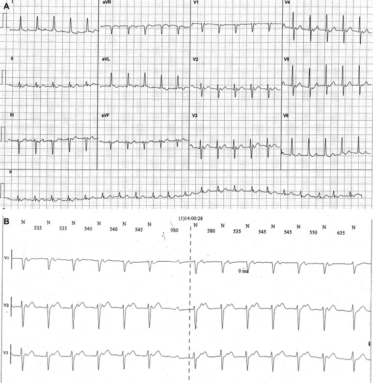
(A) Narrow complex tachycardia at ventricular rate of about 130 bpm. P waves are visible from V1 to V5 leads. (B) Wenckebach phenomenon at Holter monitoring allows the diagnosis of atrial tachycardia.
Case Report 2
A 79‐year‐old female patient, affected by metabolic syndrome, presented to the hospital's Emergency Department for palpitations. The ECG (Fig. 2A) shows an NCT at ventricular rate of about 145 bpm with regular RR intervals and without visible P waves. In this case, the most probable diagnoses are JT and common AVNRT.5 Vagal maneuvers were ineffective to stop the tachycardia but adenosine administration caused a temporary block of some ventricular beats, so that the P waves became visible and the diagnosis of AT was possible (Fig. 2B).
Figure 2.
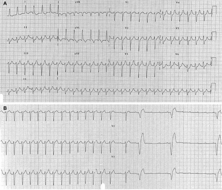
(A) Regular narrow complex tachycardia at ventricular rate of about 145 bpm without visible P waves. (B) Adenosine administration causes a temporary block of some ventricular beats, P waves become visible and diagnosis of atrial tachycardia is possible.
CLASSIFICATION
In the old ECG classification, AT was subdivided in unifocal and multifocal. Unifocal AT was defined by a slower P‐wave rate (<200/min) and an isoelectric interval between P waves.6 Atrial flutter (AF) and unifocal AT were two distinct entities and they were differentiated by two criteria: heart rate higher than about 240–250/min in AF but not in AT and presence of isoelectric baselines between atrial deflections in AT, but not in AF (Fig. 3).2, 7
Figure 3.
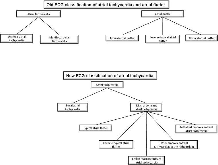
Flowchart of old and new classification of atrial tachycardia and atrial flutter.
In 2001, a new classification of AT discriminated two types of AT: focal and macroreentrant (Fig. 3).2 It was an electrophysiological classification and it showed limits of old ECG classification (isoelectric baseline did not discriminate between AT and AF). Multifocal AT did not be cited, AF was included in the macroreentant group and some subtypes of macroreentrant AT had not precise ECG criteria (Table 1). However, although sometimes ECG and anatomical substrate did not coincide, focal AT and AF had well‐defined ECG criteria.
Table 1.
ECG Characteristics of the Various Types of Atrial Tachycardia According to Old and New Classification (Changes between Old and New Classification are Shown in Bold)
| Heart Rate | P‐Wave Morphology | Isoelectric Line | ||||
|---|---|---|---|---|---|---|
| Old Classification | New Classification | Old Classification | New Classification | Old Classification | New Classification | |
| Focal atrial tachycardia | 150–250 bpm | From 100 to >300 bpm | Any | Any | Yes | Yes |
| Typical atrial flutter | 250–350 bpm | From <150 to >300 bpm | II, III, aVF − V1 + | II, III, aVF − V1 + | No | No |
| Reverse typical atrial flutter | 250–350 bpm | From <150 to >300 bpm | II, III, aVF + V1 − | II, III, aVF + V1 − | No | No |
| Lesion macroreentrant atrial tachycardia | / | From 100 to >300 bpm | / | Any | / | Possible |
| Other macroreentrant tachycardias of the right atrium | / | From 100 to >300 bpm | / | II, III, aVF − | / | Possible |
| Left atrial macroreentrant atrial tachycardia | / | From 100 to >300 bpm | / | V1 + | / | Possible |
| Atypical atrial flutter | 250–350 bpm | From 100 to >300 bpm | Any | Any | Yes | No |
| Multifocal atrial tachycardia | ≥100 bpm | / | ≥3 morphologies | / | Yes | / |
Focal ATs
Focal ATs are characterized by a point source with concentric spread of activation from the origin.8 They appear to be caused by abnormal automaticity, microreentry, and triggered activity (associated with delayed after‐depolarizations).8 The focus originates from an area of atrial myocardium arbitrarily defined as ≤2 cm in diameter.2, 9 AT cycle length is usually ≥250 ms but it can be as short as ≤200 ms and it can exhibit important variations.2 A progressive rate increase at tachycardia onset (warm up) and/or a progressive rate decrease before tachycardia termination (cool down) are suggestive of an automatic mechanism.2 Typically, adrenergic stimulation can accelerate the rate of focal discharge.2
A common misconception is that focal AT is a sign of underlying heart disease.6 Indeed, the majority of histological analyses conducted on myocardium from AT focuses have shown normal findings.6 Locations of slow conduction and anisotropy provide the substrate for microreentry and the initiation of focal AT.6 Reduction in tissue voltage and conduction slowing occur with aging; for these reasons, the microreentry is a more common mechanism for focal AT in the older population.6
ECG pattern of AT shows typically discrete P waves at rates 130–240 bpm, but possibly as low as 100 bpm or as high as 300 bpm.2 There is a clearly defined isoelectric baseline between P waves in all leads.2, 10 P‐wave morphology (PWM) will depend on focus location, and it can be used to approximately localize it before electrophysiological study.2
Adenosine can effectively terminate focal AT related to triggered activity and microreentry, whereas the response in automatic AT is generally of transient suppression.6 Moreover, calcium‐channel blockers and beta‐blockers can terminate AT owing to enhanced automaticity or triggered activity.2, 6 Finally, class Ic and III drugs can also terminate or reduce recurrence of focal AT.6
Macroreentrant ATs
Macroreentrant ATs include typical AF and other well characterized macroreentrant circuits in right and left atrium (LA; Table 1). The mechanism is reentrant activation around a large central obstacle, generally several centimeters in diameter, at least in one of its dimensions.2 The central obstacle may consist of normal or abnormal structures and it can be fixed, functional, or a combination of each.2
Typical AF is the most common macroreentrant AT.2 It usually has a cycle length between 190 and 250 ms, with ≤2% cycle‐to‐cycle variation.2 However, conduction delays within the circuit can prolong the AT cycle length, particularly after radiofrequency ablation, making it overlap with the classical focal AT range (>400 ms cycle length).2 In typical AF, activation of the right atrium (RA) is reentrant, bounded anteriorly by the tricuspid orifice, and posteriorly by a combination of anatomical obstacles (orifices of the superior and inferior vena cava and the Eustachian ridge) and functional barriers (the region of the CT).2 The superior pivot point is not well defined. The inferior pivot point is the area bounded anteriorly by the inferior part of the tricuspid orifice, and posteriorly by the inferior vena cava orifice and its continuation in the eustachium ridge (inferior isthmus).2 Complete transection or ablation of this isthmus interrupts and prevents typical AF.2 The most common direction of activation in the circuit (90% of clinical cases) is in the descent in the case of anterior and lateral walls and in the ascent in the septal and posterior walls of the RA; this has been described as counterclockwise reentry.2 The opposite direction of activation, descending the septum, and ascending the anterior (clockwise reentry) occurs in 10% of clinical cases and characterizes reverse typical AF.2
Typical AF (Fig. 4) presents a characteristic ECG “sawtooth” pattern on the inferior leads; it consists of a downsloping segment, followed by a sharper negative deflection, then a sharp positive deflection with a positive “overshoot” leading to the next downsloping plateau.2 Lead V1 often shows a positive deflection (but biphasic or negative deflections can be seen in some cases).2 Leads I and aVL characteristically show low voltage deflections.2
Figure 4.
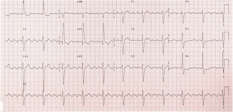
A 4:1 typical atrial flutter (see text for discussion).
Reverse typical AF can be recognized with a high degree of reliability in the presence of broad, positive deflections on the inferior leads.2 Wide negative deflections in V1 may be the most specific diagnostic sign.2 Nevertheless, morphologies similar to that of typical AF and other atypical patterns have been reported.2
The lesion macroreentrant ATs have an atriotomy scar as central obstacle of the circuit. Other obstacles may also include anatomical structures located in the vicinity of the scar (superior or inferior vena cava).2 The ECG pattern can range from a morphology similar to typical AF, to that which is characteristic of classical AT.2
Other macroreentrant tachycardias of the RA appearing either after ablation or pacing in patients with typical flutter have been characterized; the ECG in these types of tachycardia tend to show negative atrial complexes in the inferior leads.2
Finally, the left atrial macroreentrant ATs can result in ECG patterns of AT (discrete P waves and isoelectric baseline), typical AF or atypical AF with usually a predominantly positive F‐wave morphology in lead V1.2 They can occur after atrial fibrillation ablation as macroreentrant tachycardias around larger anatomic barriers such as the mitral annulus or previously isolated pulmonary veins (PVs).11
With reference to this classification, the term atypical AF does not identify a specific anatomical substrate but it could be used to define any tachycardia fulfilling the classical ECG definition of a continuously undulating pattern but not fitting the typical and reverse typical flutter patterns described above.2
LOCALIZATION OF FOCAL AT
Several algorithms for localizing ATs based on PWM have been developed.12, 13, 14 They are subject to error because interpretation of the standard ECG is limited by several factors: focal ATs tend to be paroxysmal, the P wave may be buried within the T wave, and the criteria may not be as accurate in the presence of significant underlying atrial enlargement or conduction delay.8 Nevertheless, the surface ECG is a very helpful tool in directing mapping to particular areas of interest.15
The foci responsible for focal AT do not occur randomly throughout the atria but tend to cluster at characteristic anatomical locations (Table 2).6
Table 2.
Differential Diagnosis of Foci Responsible for Focal Atrial Tachycardia
| I | II | III | aVR | aVL | aVF | V1 | V2 | V3 | V4 | |
|---|---|---|---|---|---|---|---|---|---|---|
| CT | + | + | − | +/− or + | ||||||
| TA | + or iso | + | − | − | ||||||
| RAA | low + | low + | low + | − or iso | ||||||
| CS mid‐body | deep − | deep − | + | deep − | + | iso | iso | |||
| CS ostium | deep − | deep − | + | deep − | iso | iso | ||||
| Perinodal/septal right | iso or − | |||||||||
| Left PVs | iso | broad, notched + | broad, notched + | − | − or iso | broad, notched + | broad, notched + | + | + | + |
| Right PVs | + | − | − or iso | + | + | + | + | |||
| Superior PVs | + | + | − | − or iso | + | + | + | + | + | |
| Inferior PVs | − | − or iso | + | + | + | + | ||||
| LAA | − | + | + | + | + | |||||
| AM continuity | iso | iso | iso or − | iso | −/+ | |||||
| Noncoronary cusp of aortic valve | + | low −/+ | low −/+ | + | low −/+ | − | − | |||
| Perinodal/septal left | + or −/+ |
CT = crista terminalis; TA = tricuspid annulus; RAA = right atrial appendage; CS = coronary sinus; PVs = pulmonary veins; LAA = left atrial appendage; AM = aortomitralic; iso = isodiphasic; + = positive; − = negative; iso = isodiphasic; +/− = positive/negative; −/+ = negative/positive.
Right Atrium
This group of ATs appears to have more often an incessant behavior that may cause a tachycardia mediated cardiomyopathy.16
The CT is the origin of two‐thirds of right‐sided focal AT.17 It is the embryological junction of the smooth and trabeculated RA and an area of marked tissue anisotropy, providing the potential substrate for microreentry.18 The properties of automaticity due to resident nodal tissue combined with anisotropic conduction explain the propensity for atrial arrhythmias to originate from this location.6 The majority of these foci arose from the superior and mid‐CT and, therefore, may have similar PWM to sinus rhythm.12, 15, 19 Suggestive ECG criteria of AT originating from the CT are: positive–negative V1 P wave (or positive V1 during tachycardia and sinus rhythm), positive P wave on the I and II leads and negative in aVR.12, 13, 15
Tricuspid annulus (TA) is the second most common site of origin for right ATs.15 PWM can vary markedly according to where on the annulus the focus is located.15 Generally, there is an inverted P wave in V1 and V2 and the polarity of leads II and III is deeply negative for an infer anterior location, and low amplitude, positive, or biphasic for a superior location.12, 15 Other P‐wave characteristics are positive in aVL and positive or isoelectric in lead I.15
The right atrial appendage (RAA) (pectinated region of the RA) extends from the CT posteriorly to the triangulated component anteriorly.16 Due to their close anatomic proximity, these tachycardias are generally indistinguishable from superior tricuspid annular foci.12 Nevertheless, suggestive ECG criteria of AT from RAA is: negative P wave in V1 (sometimes biphasic) and low amplitude positive P waves on the inferior leads.14, 15, 16
PWM of ATs originating from coronary sinus (CS) is highly characteristic with deeply inverted P waves on the inferior leads and invariably positive in aVR.15 P wave is positive in V1 and negative in V6 with a transition at V3 or V4 in ATs from CS mid‐body or musculature; on the contrary, this transition occurs between V1 and V2 for ATs originating at the CS ostium.20 It has been found that arrhythmias originating from the region of the os were due to abnormal automaticity while those arising from deep within the CS were triggered rhythms that could be abolished with verapamil.20, 21
For right perinodal and right septal an isoelectric P wave in V1 is highly specific but not very sensible12; however, these tachycardias may also exhibit a negative polarity on the V1 lead.15, 22 Moreover, the duration of P waves is shorter than that of sinus rhythm.13 Chen et al. described a high sensitivity of right septal AT to adenosine.22
Left Atrium
Previous studies suggested that a positive P wave in V1 and a negative P wave in aVL were relatively specific for a left atrial origin.14
In the LA, the predominant site of origin for focal AT is the ostia of the PVs.6 Their posterior location within the LA is reflected by the universal finding of a positive P wave in V1 and across the precordial leads.12 Almost all foci are also negative in aVR and negative or isoelectric in aVL.12 The left‐sided veins have a broader, notched P wave in V1 and on the inferior leads.12 Right‐sided PV foci usually have a positive P wave in lead I.12 The superior PVs invariably have a positive P wave on the inferior.15 The inferior veins may have inverted, low‐amplitude positive or isoelectric inferior P waves.15 The ostia of the PVs are common sites of origin of ATs occurring after atrial fibrillation ablation.11
The left atrial appendage (LAA) is closely approximated with the left superior PV and, as such, has a similar PWM.19 A negative P wave in lead I combined with a positive P wave in lead V1 and the inferior leads is highly suggestive of an LAA origin.23 In general, a deeply negative tachycardia P wave in lead I distinguish foci at the LAA from those arising at the right‐ (positive P wave) and left‐ (isoelectric P wave) sided PVs.24
Although AT foci have been described from a range of mitral annular sites, several studies have reported that the majority cluster at the aortomitral continuity adjacent to the left fibrous trigon.15 ATs arising from this region characteristically have a biphasic negative–positive appearance in V1 and an isoelectric or negative P wave in aVL.15 Inferior leads were usually low amplitude or isoelectric.12
Recently, AT has been described originating from the no coronary cusp of the aortic valve.15 Due to the close anatomic proximity, the P wave description is similar to that of those arising from the aortomitral continuity. Nevertheless, the P waves in leads V1 and V2 are usually negative and it is present an upright P wave in leads I and aVL.25 The inferior leads are biphasic negative–positive but of low amplitude.15
Left septal and left perinodal foci may demonstrate either a positive P wave in V1 or a biphasic negative–positive appearance; variable findings in limb leads have been reported.15 P‐wave duration during tachycardia is significantly shorter than during sinus rhythm.26, 27 Verapamil possesses a relatively high success rate in terminating left septal AT, while this tachycardia seems to be resistant to adenosine; for this reason, microreentry has been hypothesized as the underlying mechanism of this tachycardia.27
DIFFERENTIAL DIAGNOSIS BETWEEN AT AND OTHER SVTS
AT is a simple diagnosis whenever there are well visible P waves on the ECG and the AV conduction is variable or constant but more than 1:1 because it appears as an NCT with identical P waves and regular PP intervals (Fig. 5). However, in presence of 2:1 AT, the diagnosis may be uncertain because P waves may be concealed by QRS complex or T waves so that only one or no P wave is visible on the ECG.1
Figure 5.
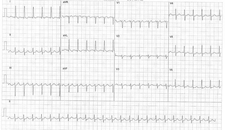
A 2:1 atrial tachycardia at ventricular rate of 140 bpm with well visible P waves on the V1 lead.
In order to correctly differentiate an AT from other NCTs, we propose a simple diagnostic algorithm with a step‐by‐step approach (Fig. 6). In presence of irregular NCT, it is simple to formulate an univocal and conclusive diagnosis. However, the regular tachycardias lead often to two or more conclusions. Particularly, any regular NCT without AV dissociation could be an AT. Therefore, in order to correctly diagnose an AT, it is important to know all the possible alternative diagnosis (Fig. 6) and their characteristics (Table 3).
Figure 6.
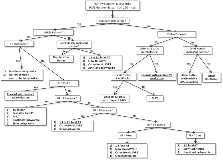
Diagnostic algorithm for the narrow complex tachycardias. The figure shows a flow chart with a step‐by‐step approach. Diagnoses are shown in bold. Diagnoses of focal atrial tachycardia are underlined. AV = atrioventricular; AT = atrial tachycardia; AVNRT = atrioventricular nodal reentry tachycardia; AVRT = atrioventricular reciprocating tachycardia; PACs = premature atrial contractions; MAT = multifocal atrial tachycardia; PFRJT = permanent form of junctional reciprocating tachycardia.
Table 3.
Differential Diagnosis of SVTs with Identical P Waves and Regular PP Intervals
| Paroxy‐ | P‐Wave | PR and RP | Possible Variability | |||
|---|---|---|---|---|---|---|
| smal | Trigger | Morphology | P:R Ratio | Intervals | of PP and RR Intervals | |
| AT | Yes | Sudden | Any | Any | Any | Yes |
| Slow–fast AVNRT | Yes | PAC with PR prolongation | Retrograde and concentric | 1:1 | RP < 70 ms | No |
| Slow–slow AVNRT | Yes | PAC or PVC | Retrograde and concentric | 1:1 | RP < PR but > 70 ms | No |
| Fast–slow AVNRT | Yes | PVC | Retrograde and concentric | 1:1 | RP > PR | No |
| JT | Yes | Sudden | Retrograde and concentric | 1:1 or AV dissociation | P wave adjacent to QRS | Yes |
| Orthodromic AVRT | Yes | PAC or PVC | Any | 1:1 | RP > 70 ms | No |
| PFRJT | No | Rate‐dependent | Any | 1:1 | RP > PR | No |
| ST | No | Gradual | Sinus | 1:1 | Any | Yes |
AT = atrial tachycardia; AVNRT = atrioventricular nodal reentry tachycardia; JT = junctional tachycardia; AVRT = atrioventricular reciprocating tachycardia; PFRJT = permanent form of junctional reciprocating tachycardia; ST = sinus tachycardia; PAC = premature atrial contraction; PVC = premature ventricular contraction; AV = atrioventricular.
In presence of 1:1 AV conduction, focal AT is associated typically with a long and variable RP relationship on the ECG.6 This tachycardia should be differentiated from the other SVTs with RP interval longer than PR interval (RP > PR). They may be: sinus tachycardia, uncommon AVNRT, permanent form of functional reciprocating tachycardia (PFRJT), and JT.1 Sinus tachycardia is no paroxysmal and it has a sinus PWM; rarely, in presence of first‐grade AV block, it could appear with a RP interval shorter than PR interval.1 Uncommon AVNRT is characterized by narrow and negative P waves on the inferior leads but positive on the V1 lead (retrograde conduction).1 It is usually initiated by a ventricular premature depolarization, is rarely sustained and it is typically constant.1, 6, 27 The PFRJT or reciprocating tachycardia of Coumel is a particular orthodromic atrioventricular reciprocating tachycardia (AVRT) with an accessory pathway at low velocity (rate dependent) of conduction.28 It presents a no paroxysmal but incessant trend.1 Finally, JT may rarely present retrograde P waves before QRS complex (negative on the inferior leads and positive in V1).1
If an SVT presents a 1:1 AV conduction with almost identical RP and PR intervals (RP = PR) and not sinus P wave, it may be a 1:1 AT or a 2:1 AT with a P wave concealed by QRS complex (Fig. 7). In this case, AT should be distinguished from sinus tachycardia and orthodromic AVRT. However, this tachycardia is usually triggered by an atrial or ventricular beat, it may present any PWM and it is typically constant.1
Figure 7.
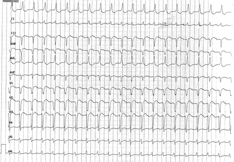
A 2:1 atrial tachycardia with only one visible P wave (other P is concealed by QRS complex). Diagnosis is prompted by: PR = RP interval, P wave visible only in some leads and upsloping PR segment in II lead. Moreover, II lead shows a QRS complex followed by the end P wave.
Sometimes a 1:1 focal AT can show a short RP interval, particularly at higher rates and increased AV node conduction.6 When RP is shorter than PR interval (RP < PR) but RP interval is longer than 70 ms (RP > 70 ms), focal AT should be differentiated from orthodromic AVRT, slow–slow AVNRT, and sinus tachycardia.1 Slow–slow AVNRT is rare, it presents narrow and retrograde P waves and it is typically constant.1
Finally, if RP interval is shorter than 70 ms (RP < 70 ms), it is necessary to differentiate focal AT from common AVNRT and JT. The common AVNRT is the most frequent form of paroxysmal SVT.1, 3 It is a constant SVT that starts frequently with a supraventricular ectopic beat that presents a prolongation of the PR interval on the ECG.1 P waves are narrow and they have a retrograde morphology as well as JT.1
Whenever there is an SVT without visible P waves and without undulating pattern, it may be: 1:1 or 2:1 AT, common AVNRT, orthodromic AVRT, or JT.1 In these cases, P waves are not visible because they are concealed by T waves or QRS complex.
Holter analysis could offer further details to discriminate between AT and another SVT. It could show start and finish typical of other SVTs and some suggestive characteristics of AT. In fact, AT secondary to enhanced automaticity presents generally a progressive rate increase at tachycardia onset (warm‐up) and/or a progressive rate decrease before tachycardia termination (cool down).2 Moreover, PP and RR intervals may vary slightly during AT.6 Finally, a Wenckebach conduction during an SVT is suggestive of AT.4
According to these criteria, AT is sometimes a diagnosis of exclusion on the ECG (Table 3). Therefore, if the diagnosis is uncertain, it is possible to utilize vagal maneuvers, such as sinus carotid massage, or adenosine administration.6 They cause generally a transient suppression of AV node so that P waves become evident and the diagnosis of AT is feasible.6 However, adenosine can effectively terminate focal AT related to triggered activity and microreentry29 as well as reentry tachycardias (AVRT or AVNRT).
CONCLUSIONS
AT is a paroxysmal SVT that could present: any PWM, any AV conduction, any RP or PR intervals, and a “warm‐up” and “cool‐down” phenomenon. Our ECG reports represented a diagnostic challenge in our clinical practice and they showed as any SVT with identical P waves and regular PP or RR intervals could be an AT. However, a good knowledge and interpretation of the ECG could help the physician to differentiate focal and macroreentrant AT from the other SVTs and to manage and to treat correctly these patients; moreover, the PWM analysis could be a very helpful tool in directing mapping during electrophysiological study.
In this article, we showed two ECG reports and a review of main current electrocardiographic findings about AT.
Conflicts of interest: none.
REFERENCES
- 1. Buttà C, Tuttolomondo A, Di Raimondo D, et al. The supraventricular tachycardias: Proposal of a diagnostic algorithm for the narrow complex tachycardias. J Cardiol 2013;61:247–255. [DOI] [PubMed] [Google Scholar]
- 2. Saoudi N, Cosìo F, Waldo A, et al. A classification of atrial flutter and regular atrial tachycardia according to electrophysiological mechanisms and anatomical bases. A statement from a joint expert group from the working group of arrhythmias of the European Society of Cardiology and the North American Society of Pacing and Electrophysiology. Eur Heart J 2001;22:1162–1182. [DOI] [PubMed] [Google Scholar]
- 3. Blomström‐Lundqvist C, Scheinman MM, Aliot EM, et al. ACC/AHA/ESC guidelines for the management of patients with supraventricular arrhythmias—Executive summary. A report of the American College of Cardiology/ American Heart Association Task Force on Practice Guidelines and the European Society of Cardiology Committee for Practice Guidelines. J Am Coll Cardiol 2003;42:1493–1531. [DOI] [PubMed] [Google Scholar]
- 4. Oreto G: I disordini del ritmo cardiaco. Torino, Centro Scientifico Editore, 1997. [Google Scholar]
- 5. Buttà C, Tuttolomondo A, Di Raimondo D, et al. Effect of atrial capture beats on the subsequent cycle during slow common atrioventricular nodal reentry tachycardia. J Cardiovasc Electrphysiol 2013;24:474–475. [DOI] [PubMed] [Google Scholar]
- 6. Rosso R, Kistler PM. Focal atrial tachycardia. Heart 2010;96:181–185. [DOI] [PubMed] [Google Scholar]
- 7. Buttà C, Tuttolomondo A, Di Raimondo D, et al. A re‐entry tachycardia triggered by the spontaneous interruption of an atrial tachicardia. J Cardiovasc Med 2013. [Epub ahead of print]. [DOI] [PubMed] [Google Scholar]
- 8. Lindsay BD. Focal and macro reentrant atrial tachycardia: From bench to bedside and back to the bench again. Heart Rhythm 2007;4:1361–1363. [DOI] [PubMed] [Google Scholar]
- 9. Miyazaki S, Shah AJ, Kobori A, et al. How to approach reentrant atrial tachycardia after atrial fibrillation ablation. Circ Arrhythm Electrophysiol 2011;5:e1–e7. [DOI] [PubMed] [Google Scholar]
- 10. Buttà C, Tuttolomondo A, Giarrusso L, et al. A particular bigeminy during atrial tachycardia. Neth Heart J 2014. [Epub ahead of print]. [DOI] [PMC free article] [PubMed] [Google Scholar]
- 11. Gerstenfeld EP, Marchlinski FE. Mapping and ablation of left atrial tachycardias occurring after atrial fibrillation ablation. Heart Rhythm 2007;4:S65–S72. [DOI] [PubMed] [Google Scholar]
- 12. Kistler PM, Roberts‐Thomson KC, Haqqani HM, et al. P‐wave morphology in focal atrial tachycardia: Development of an algorithm to predict the anatomic site of origin. J Am Coll Cardiol 2006;48:1010–1017. [DOI] [PubMed] [Google Scholar]
- 13. Tada H, Nogami A, Naito S, et al. Simple electrocardiographic criteria for identifying the site of origin of focal right atrial tachycardia. Pacing Clin Electrophysiol 1998;21:2431–2439. [DOI] [PubMed] [Google Scholar]
- 14. Tang CW, Scheinman MM, Van Hare GF, et al. Use of P wave configuration during atrial tachycardia to predict site of origin. J Am Coll Cardiol 1995;26:1315–1324. [DOI] [PubMed] [Google Scholar]
- 15. Teh AW, Kistler PM, Kalman JM. Using the 12‐lead ECG to localize the origin of ventricular and atrial tachycardias: Part 1. Focal atrial tachycardia. J Cardiovasc Electrophysiol 2009;20:706–709. [DOI] [PubMed] [Google Scholar]
- 16. Roberts‐Thomson KC, Kistler PM, Haqqani HM, et al. Focal atrial tachycardias arising from the right atrial appendage: Electrocardiographic and electrophysiologic characteristics and radiofrequency ablation. J Cardiovasc Electrophysiol 2007;18:367–372. [DOI] [PubMed] [Google Scholar]
- 17. Kalman JM, Olgin JE, Karch MR, et al. “Cristal tachycardias”: Origin of right atrial tachycardias from the crista terminalis identified by intracardiac echocardiography. J Am Coll Cardiol 1998;31:451–459. [DOI] [PubMed] [Google Scholar]
- 18. Saffitz JE, Kanter HL, Green KG, et al. Tissue‐specific determinants of anisotropic conduction velocity in canine atrial and ventricular myocardium. Circ Res 1994;74:1065–1070. [DOI] [PubMed] [Google Scholar]
- 19. Roberts‐Thomson KC, Kistler PM, Kalman JM. Focal atrial tachycardia: II. Management. Pacing Clin Electrophysiol 2006;29:769–778. [DOI] [PubMed] [Google Scholar]
- 20. Badhwar N, Kalman JM, Sparks PB, et al. Atrial tachycardia arising from the coronary sinus musculature. J Am Coll Cardiol 2005;46:1921–1930. [DOI] [PubMed] [Google Scholar]
- 21. Wit AL, Cranefield PF. Triggered and automatic activity in the canine coronary sinus. Circ Res 1977;41:434–445. [DOI] [PubMed] [Google Scholar]
- 22. Chen CC, Tai CT, Chiang CE, et al. Atrial tachycardias originating from the atrial septum: Electrophysiologic characteristics and radiofrequency ablation. J Cardiovasc Electrophysiol 2000;11:744–749. [DOI] [PubMed] [Google Scholar]
- 23. Kistler PM. The left atrial appendage: Not just an innocent bystander. J Cardiovasc Electrophysiol 2007;18:465–466. [DOI] [PubMed] [Google Scholar]
- 24. Kistler PM, Sanders P, Fynn SP, et al. Electrophysiological and electrocardiographic characteristics of focal atrial tachycardia originating from the pulmonary veins: Acute and long‐term outcomes of radiofrequency ablation. Circulation 2003;108:1968–1975. [DOI] [PubMed] [Google Scholar]
- 25. Ouyang F, Ma J, Ho SY, et al. Focal atrial tachycardia originating from the non‐coronary aortic sinus: Electrophysiological characteristics and catheter ablation. J Am Coll Cardiol 2006;48:122–131. [DOI] [PubMed] [Google Scholar]
- 26. Frey B, Kreiner G, Gwechenberger M, et al. Ablation of atrial tachycardia originating from the vicinity of the atrioventricular node: Significance of mapping both sides of the interatrial septum. J Am Coll Cardiol 2001;38:394–400. [DOI] [PubMed] [Google Scholar]
- 27. Marrouche NF, SippensGroenewegen A, Yang Y, et al. Clinical and electrophysiologic characteristics of left sepal atrial tachycardia. J Am Coll Cardiol 2002;40:1133–1139. [DOI] [PubMed] [Google Scholar]
- 28. Ganz LI, Friedman PL. Supraventricular tachycardia. N Engl J Med 1995;332:162–173. [DOI] [PubMed] [Google Scholar]
- 29. Chen SA, Chiang CE, Yang CJ, et al. Sustained atrial tachycardia in adult patients. Electrophysiological characteristics, pharmacological response, possible mechanisms, and effects of radiofrequency ablation. Circulation 1994;90:1262–1278. [DOI] [PubMed] [Google Scholar]


