Abstract
In addition to knowledge of normal and pathological patterns, the correct interpretation of electrocardiographic (ECG) recordings requires the use of acquisition procedures according to approved standards. Most manuals on standard electrocardiography devote little attention to inadequate ECG recordings. In this article, we present the most frequent ECG patterns resulting from errors in limb and precordial lead placement, artifacts in 12‐lead ECG as well as inadequate filter application; we also review alternative systems to the standard ECG, which may help minimize errors.
Keywords: electrocardiogram, artifacts, electrode misplacement, filters, leads
In addition to knowledge of normal and pathological patterns, the correct interpretation of electrocardiographic recordings requires the use of acquisition procedures according to approved standards. 1 Many electrocardiograms (ECGs) obtained in routine daily practice present inadequate lead placement. Heden et al., 2 using automated ECG analysis software, showed that 2% of more than 11,000 ECGs analyzed presented lead placement interchange. To these errors, others must surely be added—those frequently presenting due to high precordial lead displacement and, less frequently, those produced when limb leads are placed on the chest.
The presence of artifacts in ECG recordings may induce important diagnostic errors leading to unnecessary therapeutic interventions, 3 such as antiarrhythmic treatment or the implantation of pacemakers or defibrillators. In this respect, Knight et al. 4 showed that 38% of nearly 500 electrophysiologists participating in their study diagnosed as ventricular tachycardia what was in fact an artifact.
Most manuals on standard electrocardiography devote little attention to inadequate ECG recordings. In this article, we present the most frequent ECG patterns resulting from errors in limb and precordial lead placement, artifacts or inadequate filter application; we also review alternative systems to the standard ECG that may help minimize errors.
INCORRECT PLACEMENT OF LIMB LEADS
Upward Displacement
Proximal or distal placement of leads on the limbs produces different ECG tracings and should therefore be correctly performed, although great precision is not required. Positioning of the limb lead electrodes on the chest according to the Mason‐Likar system 5 causes a rightward shift of the QRS axis, thus diminishing R voltage in lead I and aVL and increasing it in leads II, III, and aVF (Fig. 1). 6 , 7 , 8 Long ago, Einthoven obtained his first recordings using distal limbs submerged in buckets of salt water. Later authors 9 , 10 recommended placing electrodes on arms and legs far from the shoulders and hips, but not necessarily on the wrists and ankles.
Figure 1.
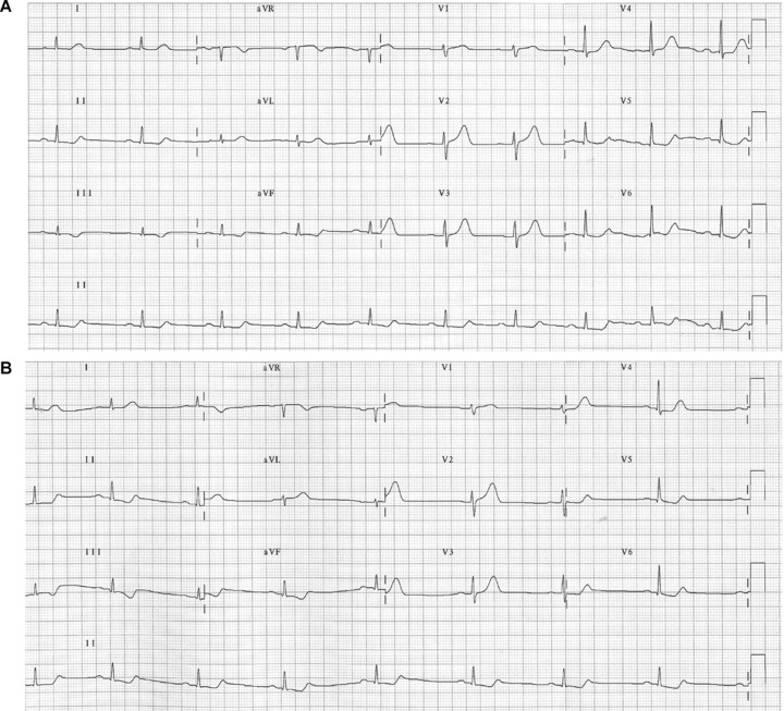
(A) Electrocardiogram of a patient with acute coronary syndrome (ACS) due to coronary descending artery occlusion, obtained with standard electrode placement. (B) Electrocardiogram of the same patient obtained with Mason‐Likar system, showing markedly reduced R voltage in lead I and aVL, and increased in lead III and aVF. The reciprocal changes in inferior leads due to coronary descending artery occlusion are further accentuated on displacement of the limb electrodes to the torso.
The introduction of single‐use adhesive electrodes, easily applied to any part of the limbs or even the chest, has significantly reduced ECG artifacts caused by movement and allowed more proximal limb lead placement. 11 Although advantageous in terms of speed and easy application, 12 the use of such electrodes with upward displacement provides ECGs that cannot be considered equivalent to standard ECGs. Any modification of the position of the limb electrodes should be recorded and taken into consideration when the ECG is interpreted.
Electrode Placement Interchange
In general, the ECG patterns recorded with limb lead interchange depend on the patient's basal ECG (Fig. 2A). However, there are well‐defined patterns resulting from incorrect lead placement, regardless of the basal ECG. For example, tracings with a practically isoelectric line in leads I, II, or III are due to misplacement of the ground lead 13 , 14 to an upper limb (Fig. 2B).
Figure 2.
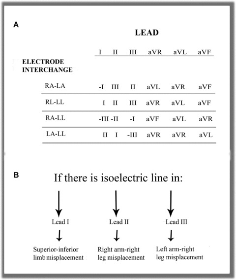
(A) The most frequent interchanges without ground electrode displacement to upper limbs. (B) The presence of an isoelectric line in Einthoven leads identifies electrode interchange when involving only two electrodes.
Contralateral Interchange
Interchange between Right and Left Arm Electrodes. This combination is one of the easiest errors to identify in routine clinical practice ECGs. Generally, the usual lead I tracing is inverted in sinus rhythm and P, QRS, and T are negative. Lead II is in fact lead III, and aVR is aVL and vice versa. With the left leg electrode correctly placed, aVF remains unaltered. The negative P wave recorded in lead I and positive in aVR, as can be observed in ectopic rhythms, is exceptional during sinus rhythm. 15 In the vertical heart, this interchange produces lead I morphology showing qR or QR and aVR showing QS complex (Fig. 3). In patients with dextrocardia, we may record morphologies similar to those obtained with right‐left arm interchange but we do not observe the usual progression of the R wave in the precordial leads. In atrial fibrillation, this technical error can be distinguished from dextrocardia by the discordance between the QRS complex in lead I, which is predominantly negative, and V6, which is positive. 16
Figure 3.
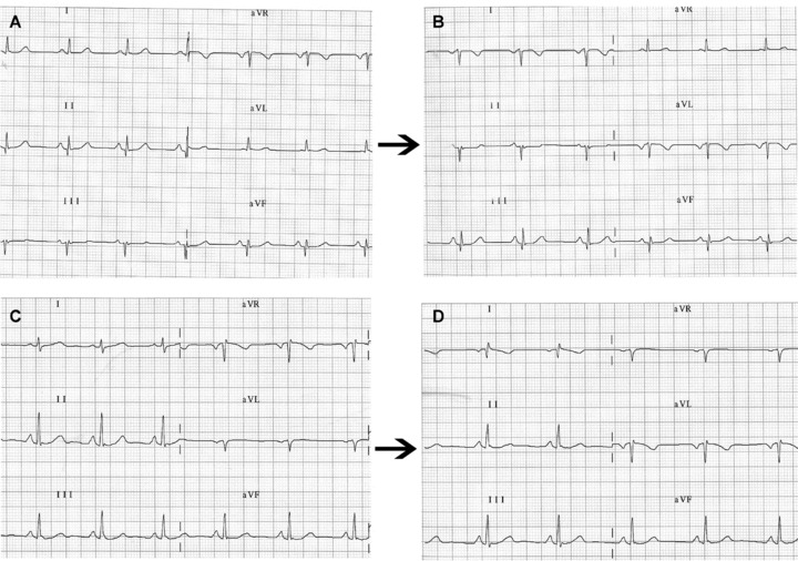
(A) Frontal plane leads in a healthy patient with left shift of the QRS electrical axis. (B) on interchanging left arm and right arm electrodes, the ECG shows the classical pattern of P, QRS, and T as negative waves in lead DI and positive in aVR. However, in the vertical heart (C) the most striking finding may be (D) a QR or qR complex in lead DI with negative P wave or negative/positive in aVR.
Interchange between the Right and Left Leg Electrodes. Interchange between the right and left leg electrodes may be overlooked in the ECG, since the potentials of the two legs are practically the same and the recording does not differ from that obtained with standard electrode placement.
Homolateral Interchange
Interchange between Right Arm and Right Leg Electrodes. The artifact generated by interchange between right arm and right leg electrodes is easily identified; it manifests as a practically isoelectric line in lead II, because there is practically no difference between the potentials of the right arm electrode (now on the right leg) and the left leg 13 (Fig. 2B). However, the difference in potential increases notably if the electrodes are elevated to the iliac crests. 17 In addition, lead I is inverted lead III while lead III is unaffected. Leads aVR and aVF are identical since the voltage recorded from the left and right legs is practically the same. Precordial lead voltages are only slightly affected.
Interchange between Left Arm and Left Leg Electrodes. Although changes are produced in all frontal plane leads except aVR, this placement error is difficult to detect. In general, the electrical axis of the P wave is more leftward than normal (30–70° in 90% of normal cases) 18 with a larger P wave in lead I than in lead II, while in lead III we occasionally observe a biphasic (−/+) P wave such as one that can be recorded in ectopic rhythms 19 (Fig. 4). Heden proposed an automated system that can detect interchange between left arm and left leg electrodes with a sensitivity of 57% and specificity of practically 100%. 2 In the presence of atrial flutter, this error is easily detected by the characteristic sawtooth morphology recorded in lead III and aVF but not in lead II. 19 If this error occurs in an acute coronary syndrome patient with ST elevation in the inferior leads due to right coronary artery occlusion, the ECG shows ST elevation in lead I and aVL and ST depression in lead III and aVF, which in principle indicates that the defective artery is not the right coronary. 20 The same occurs in chronic phase inferior myocardial infarction with Q waves in lead II, III, and aVF where this interchange “displaces” the necrosis toward lead I and aVL. 21
Figure 4.
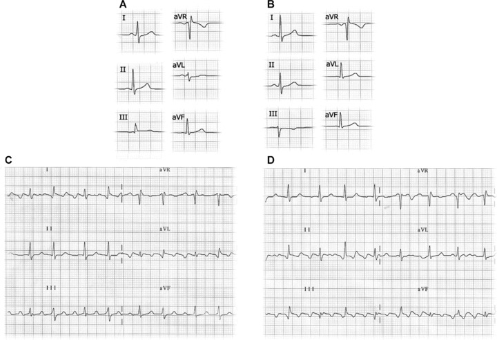
(A) Electrocardiogram recorded with left leg–left arm electrode interchange. In this case, the P axis has a left shift with a P wave in lead I and aVL amplitude greater than in lead II. In lead III, a negative P wave is recorded followed by a QRS complex with dominant R. (B) Electrocardiogram of the same patient with correctly placed electrodes with P axis at 60°. (C) Left leg–left arm electrode interchange in a patient with atrial flutter: the ECG shows the typical saw tooth morphology in lead III and aVF but not in II. (D) Electrocardiogram of the same patient with correctly placed electrodes.
Cross‐Over Electrode Interchange
Interchange between Right Arm and Left Leg Electrodes. This error produces generalized inversion of the basal ECG in all the frontal plane leads except aVL. In most cases, the recording simulates that of a chronic phase inferior myocardial infarction and nonsinus rhythm 22 with greater inversion of the P and T waves in the rS or QS complexes. The QRS is usually positive in aVR and negative in lead I, as commonly observed when the left and right arm electrodes are interchanged. In patients with previous inferior myocardial infarction, this electrode interchange can cause the Q wave in lead II to disappear, giving the impression of a less extensive infarction (Fig. 5).
Figure 5.
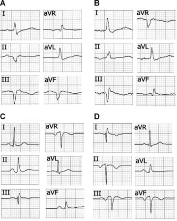
(A) Frontal plane leads in a 60‐year‐old male patient showing inferior myocardial infarction in chronic phase. (B) The same patient with right arm‐left leg electrode interchange. In this case, aVF resembles the usual aVR lead and II is inverted. The Q wave in lead II disappears and its depth in aVF is reduced, thus simulating less extension of the necrosis. (C) A 30‐year‐old woman without cardiopathy with correctly placed electrodes. (D) Tracing of the same patient with clockwise electrode rotation without ground electrode displacement, showing negative QS and P wave complexes similar to those obtained with right arm‐left leg electrode interchange obtained in a patient without previous inferior infarction.
Interchange between Left Arm and Right Leg Electrodes. The most striking aspect in this case is the presence of a practically isoelectric line in lead III (Fig. 2B) due to practically no difference in potential between the right leg electrode (negative pole) and the incorrectly placed left leg electrode (positive pole). 23 In this case, leads I and II are identical. This type of error also affects the potential of the precordial leads.
Clockwise and Anticlockwise Interchange without Misplacement of the Ground Lead
Ho and Ho 24 described these two unusual ECG patterns resulting from the misplacement of three electrodes.
Clockwise rotation generates a pattern similar to that obtained from interchanging right arm and left leg leads, with negative P waves and QRS complexes in inferior leads. Anticlockwise rotation generates a P axis with a marked right shift, with P positive in aVR and negative in lead II. Lead I and aVL are replaced by—II and aVR, respectively.
INCORRECT PLACEMENT OF PRECORDIAL LEADS
The misplacement of precordial lead electrodes is perhaps the most frequent error found when 12‐lead ECGs are performed. The degree of inexactitude in the placement of precordial electrodes is closely related with the level of technical training of the professional performing the technique. 25 This technical error may be due to
-
1
Vertical displacement of electrodes, usually toward the head.
-
2
Horizontal displacement of electrodes.
-
3
Interchange of electrodes with respect to their assigned places.
The first and second cases are more difficult to detect than the third where abnormal R wave progression reveals the technical error.
Vertical Displacement of Electrodes
The method of correct placement of the precordial leads was described long ago 26 , 27 , 28 and has recently been updated. 1 The precise identification of the intercostal spaces (IS) is necessary for such placement. 29 Of vital importance is the localization of the Sternal Angle or Angle of Louis (Fig. 6) to identify the 2nd IS and thereafter the 3rd and 4th IS. On occasions, there may be difficulty in locating the anatomical reference points, for example in obese individuals without a prominent sternal angle. A typical error when trying to locate the 1st IS is to confuse it with the costoclavicular space.
Figure 6.
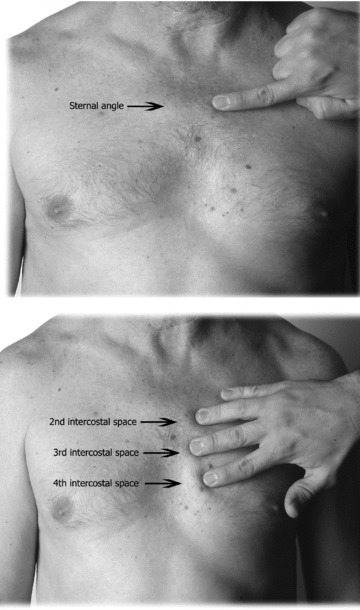
(A) From the sternal notch, the 2nd and 3rd fingers are slid down the sternum to the angle of Louis. (B) Sliding the fingers to the left or right, the 2nd intercostal is located, then downward to locate the 3rd and 4th intercostal spaces.
Another frequent error is high IS placement of V1 and V2. 30 , 31 This produces important ECG changes, especially in the P, R, and T waves. 32 Zema et al. 33 showed 1 mm reduction of the R wave for every IS involved. Certain morphological patterns are produced, and knowing them helps identify high placement of these electrodes (Fig. 7A). 34 , 35
Figure 7.
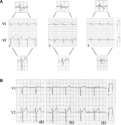
(A1) Subject without cardiopathy and the V1 and V2 electrodes correctly placed; the P wave is positive in both leads. (A2) V1 and V2 electrodes placed on the 3rd intercostal space; the P wave is positive in both leads. (A3) rSr’ pattern preceeded by a negative P wave in V1 and V2; this suggests high placement of these electrodes (on the 2nd intercostal space). (B) Leads V1 and V2 in a patient without cardiopathy and normal ST segment, obtained with electrodes correctly placed in the 4th and 3rd intercostal spaces. If the electrodes are placed on the 2nd intercostals space, we see rectification and increased ST segment in V1 and V2.
-
1
The recording of the negative component of P wave in V2 indicates high placement. This P morphology can be recorded as from the 3rd IS and is usually accompanied by an isodiphasic P wave in V1 or with a predominantly negative component.
-
2
Exclusively negative P wave in V1. In ECGs obtained from healthy subjects, the P wave in V1 is positive or diphasic type +/− with greater positive component and a slight slope. High placement of this electrode suggests that V1 is recording the tail of the resulting vector instead of the head due to atrial depolarization.
-
3
The classic rSr′ pattern with a negative P wave is exclusively indicative of V1 placement in the 2nd IS; this placement error presents in 17% of healthy individuals′ ECGs. In this case, the high placement of V1 results in recording of the third vector due to basal ventricular depolarization (r’ó R’).
The V4–V6 electrodes are sometimes placed lower and too far to the left than their correct position, 30 and furthermore, V5 and V6 are erroneously placed attempting to follow the costal curvature of the 5th IS. This is probably due to the fact that many ECG textbooks mention this anatomical reference point instead of the correct one, which is the same horizontal level as V4 at the intersection of the anterior and midaxillary line. 16 New guidelines for the standardization and interpretation of ECGs recommend placing V5 on the midline between V4–V6 when the anterior axillary line is not well defined. 1 However, V1 and V2 recordings with high IS electrode placement may be useful for increasing sensitivity to detect Brugada syndrome. 36 , 37
In women, V1 and V2 electrode placement is usually not affected by the breast size, whereas the placement of the other precordial leads, especially V4 may be complicated by large breasts. Much debate has centered on the possible voltage attenuation of the ECG waves by placing electrodes on the left breast. Colaco 38 compared R wave amplitude with electrodes placed on the breast or below it. He showed significantly reduced V3 voltage with breast placement, but no significant differences for V4. However, V5 and V6 voltage was greater with electrodes placed on the left breast compared with placement below it.
Rautaharju et al. 39 reported that the effect of breast placement on ECG wave amplitude was insignificant and therefore recommended breast placement of precordial lead electrodes to facilitate more precise positioning. However, current guidelines recommend electrode placement below the breast, pending further evidence from new studies. 1
In certain clinical situations such as acute coronary syndrome, incorrect precordial electrode placement may falsely reduce or increase signals from ischemic areas. 40 In other situations, such as chest pain of doubtful origin in combination with electrode misplacement 41 (Fig. 7B), inappropriate therapeutic intervention may be initiated.
Horizontal Displacement of Electrodes
Horizontal displacement occurs most frequently with the placement of the V3 to V6 electrodes. Thus, on performing seried ECGs as in patients with suspected ACS, small placement changes may be important for diagnosis. In this case, the use of single‐use adhesive electrodes, or skin marking to indicate the exact position of the precordial leads, will help to ensure the same electrode placement for each recording 42 (Fig. 8A). For V4 placement, visual estimation without anatomic reference points or taking the breast aureole as the midaxillary line are not infrequent practices, which involve the risk of left or right displacement of this electrode and consequently incorrect ECG tracings. A recommended method to locate the midclavicular line is to start by placing the index finger on the sternocostoclavicular joint and the middle finger on the acromioclavicular joint, then join them toward the middle of the clavicle.
Figure 8.
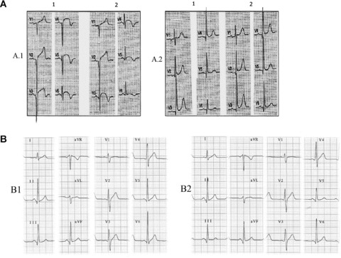
(A) Patient with acute myocardial infarction at subacute stage with V1–V6 Q waves and correctly placed precordial leads (A.1). Small changes of leftward misplacement of V3–V6 electrodes (A.2) cause significantly modified QRS morphology with qR in V6. According to classical nomenclature, the first ECG (A.1.1) would be interpreted as necrosis spreading to low lateral wall, and the second ECG (A.1.2) as no recorded spreading. A.2: Patient with inferolateral infarction (R ≥ S1 in V1) and QR in V6 (A2.1). After slight rightward displacement of the precordial leads, the QR pattern in V6 disappears. B.1: ECG of a healthy 45‐year‐old man with V6 > V5 voltage, which obliges us to review the placement of these two electrodes. B.2: Interchange between the two black colored electrodes, V5 and the ground lead (IEC), which imitates interchange between V6 and V5. In this case, we can observe the loss of S in V5 that is present in V4 and V6.
Interchange of Precordial Electrodes
This error is easily identified by the alteration it produces in the normal pattern of the R wave in precordial leads. 43 When the R wave is higher in lead V6 than in lead V5, interchange of these electrodes must be suspected, since this finding is not observed in normal ECGs 44 but can be found in left ventricular hypertrophy 45 (Fig. 8B).
INTERCHANGE BETWEEN LIMB AND PRECORDIAL ELECTRODES
This interchange generates important changes in both planes of a standard ECG, altering Wilson's Central Terminal 17 except if the interchange affects the ground electrode (Fig. 8B). The fact that the electrodes recording both planes are the same color 46 together with operator inexperience, 47 favors this type of error. There are two different systems of color coding and cable labeling (Fig. 9), one recommended by the American Heart Association (AHA) and the other by the International Electrotechnical Commission (IEC).
Figure 9.
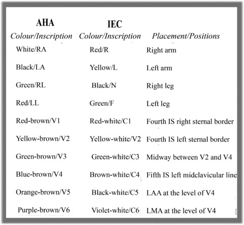
Electrode color coding and labeling system for electrocardiograms recommended by the American Heart Association and the International Electrotechnical Commission.
ARTIFACTS THAT SIMULATE ARRHYTHMIAS IN THE 12‐LEAD ECG
The literature contains numerous cases of artifacts simulating cardiac arrythmia. 48 , 49 , 50 In general, most artifacts are directly attributable to patient factors such as tremor or voluntary movements during ECG recording; however, they are also caused by deficient electrode‐skin contact.
Confusing an artifact with an important diagnostic entity may lead to inappropriate clinical intervention. Serious error may occur when an artifact results in diagnosis of ventricular tachycardia, for example, and unnecessary diagnostic and therapeutic procedures for the patient. 2 In this case, the artifact may easily be identified if any of the 12 leads presents basal rhythm of the patient. In other cases, it is necessary to perform a detailed examination of the basal complexes underlying the artifactual tracing appearing as a spike (R wave) or a notch 51 (Fig. 10A). For this, a useful procedure is to identify the basal rhythm with a pair of compasses.
Figure 10.
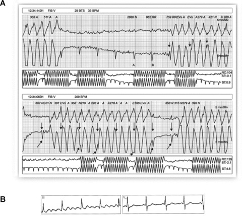
(A) Healthy 35‐year‐old patient, with palpitations. Holter recording shows rapid bursts with wide complexes and morphology similar to that of ventricular flutter. Detailed examination of the recording allows identification of the basal rhythm (arrows) hidden among the wide artifactual complexes. (B) Patient with Parkinson's disease whose ECG simulates atrial flutter in DIII while V4 clearly shows P waves.
It is important to know that certain artifacts may sometimes simulate atrial waves. These artifacts may be produced by diaphragmatic contractions (singultus or hiccups) and also recording problems arising from involuntary patient movement such as tremor (Parkinson's disease). In the latter case, the artifact is usually more evident in the frontal plane leads, and the basal rhythm of the patient may be present in the precordial leads (Fig. 10B). The problem may disappear on placing the limb electrodes as proximal as possible, 52 bearing in mind the need to record the modifications made in electrode placement. Davidenko and Snyder 53 showed that on numerous occasions baseline artifacts lead to misdiagnosis of atrial fibrillation by medical staff, especially when there was irregular ventricular rhythm and low P wave amplitude.
IMPROPER FILTER APPLICATION
Improper filter application is relatively frequent in ECGs performed in daily clinical practice, as shown by Kligfield and Okin. 54 In the great majority of the ECGs they studied, filters were applied that did not conform to the standards established by AHA in 1975. The most prevalent deviation from standard was reduced high‐frequency cutoff, which was present in 96% of tracings with nonstandard bandwidth (most commonly 40 Hz). Increased low‐frequency cutoff was present in 62% of ECGs in which it was documented.
The objective of filtering 12‐lead ECG recordings is to reduce unwanted signals, noise and interference, and thus provide an ECG of maximum quality. Among the most important signals that may provoke artifacts are those produced by the electrical power line and electromiographic signals produced by normal or abnormal muscular activity (Parkinson's disease and others) (Fig. 11A). However, acquiring ECGs with clean amplification and high gain is no easy task; filtering should only minimally distort or modify the original unfiltered cardiac signals.
Figure 11.
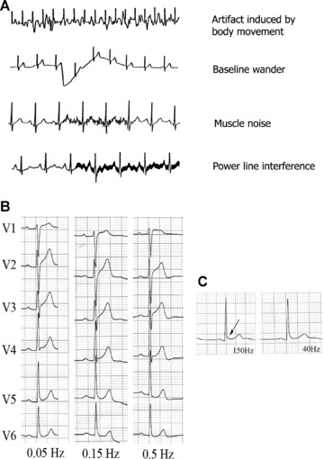
(A) Examples of artifacts caused by different circumstances. (B) Effect on the ST segment on manually applying three different low‐frequency filters to precordial lead signals, in a healthy patient with early repolarization. A striking elevation of the ST segment is observed in V1 and V2 on applying the 0.5 Hz filter, but not when the standard recommended filter (0.05 Hz) is applied. (C) Lead V5 in a healthy 23‐year‐old man with early repolarization. The J wave is visible on applying the low‐pass filter at 150 Hz (arrow), but this disappears on reducing the frequency to 40 Hz.
The filters habitually applied in electrocardiography are as follows:
-
1
Alternating current filtering.
Alternating current frequency varies from 50 Hz (e.g., in Spain) to 60 Hz (e.g., in USA). Modern ECG recorders incorporate a notch filter that selectively attenuates the frequency of the interference produced by the electrical power line with a very narrow range of frequency so as not to significantly affect cardiac signals. 55 This filter cannot normally be deactivated from the keyboard, although some recorders allow this.
-
2
Low‐frequency high‐pass filter.
Low frequency interference presents as baseline wander in the ECG. The low‐frequency high‐pass filter is important to attenuate this, which occurs with patient movement and breathing. Current AHA guidelines 1 establish a low‐frequency filter cutoff of 0.05 Hz, which may be up to 0.67 Hz if linear filters are used with zero distortion phase. 56 Using this filter to eliminate baseline sway or wander without distorting the ST segment may prove difficult on occasions (Fig. 11B). The use of conventional analogue filters with a frequency cutoff of 0.5 Hz may produce significant alterations of the ST segment. 57 , 58 , 59 This situation is particularly important in nonlinear phases, when the frequency and wave amplitude change suddenly, as occurs at the end of the QRS complex and the beginning of the ST segment. 60 To avoid potentially important distortion from the clinical point of view, it is necessary to use a linear phase filter or a low‐frequency filter set at 0.05 Hz.
Bidirectional linear phase filters are most commonly used; they apply the same high‐pass filter in the forward direction and then again in the reverse‐time direction. This type of filter presents two important features: (1) They double the filtering order (while only doubling the filtering computational cost instead of multiplying it by a factor of four) and (2) they do not produce signal delay, which may be prolonged when dealing with high‐order linear filters. Biderectional filters require storage of the signal in the computer memory for reverse‐time filtering. From a practical point of view, this means that reverse‐time filtering cannot be carried out when performing the ECG in real time (manual mode) 54 Alternative linear methods can be applied in real time, although there may be some signal delay.
-
1
High‐frequency low‐pass filters.
High‐frequency filters should be at least 150 Hz for adolescents and adults and up to 250 Hz for children. 1 It must be remembered that a high‐frequency filter set too low, at 40 Hz for instance, eliminates most of the noise but also eliminates high‐frequency signals that may be important from a clinical point of view (Fig. 11C) for example pacemaker peaks, R wave voltage, QRS notches, etc. 61
ALTERNATIVES TO STANDARD ECG RECORDING
The different problems arising from incorrect electrode placement described above are directly related to the fact that standard 12‐lead electrocardiography requires the correct placement of 10 electrodes. This number of electrodes may constitute a source of error. Much debate has therefore centered on the idea of developing more simplified recording systems.
In certain clinical settings, alternative ECG recording with simplified electrode placement is performed. Although any change in standard electrode positioning causes ECG wave alterations, this has little effect in continuous cardiac monitoring where the objective is to detect gross alterations in cardiac rhythm. Precisely in this setting, different more simplified systems of electrode placement have been used; 62 however, these present important limitations for ECG analysis.
The following two alternative systems developed in recent years are widely used:
-
1
Mason‐Likar system.
In 1966, Mason and Likar 5 introduced a modification of standard electrode placement to overcome signal distortion due to muscle activation in exercise ECG, placing standard limb electrodes on the torso. The right arm electrode in the Mason‐Likar modification is assigned to a point in the infraclavicular fossa medial to the border of the deltoid muscle. The left arm electrode is located similarly on the left side. The left leg electrode is placed on the anterior axillary line half way between the costal ridge and the left iliac crest (this position is not critical) and finally, the right leg electrode is habitually placed in the region of the right iliac fossa but can be placed elsewhere.
The rapid and easy applicability of this modification 11 , 12 together with elimination of artifacts caused by limb movement has promoted its use in resting ECG recording. However, significant variations are observed between standard and the Mason‐Likar ECG, 6 , 7 , 8 as mentioned previously. The Wilson Central Terminal is notably affected, with reduced R wave amplitude in precordial leads and right shift of the axis in the frontal plane (Fig. 1).
Although the Mason‐Likar electrode positions have been suggested for use in routine 12‐lead ECG, 63 an appropriate system for converting recording data obtained from standard positioning to the alternative is necessary, 64 primarily for the limb lead measurements 62 or, although more complicated, the creation of new diagnostic standards adapted to this system.
-
2
EASI system.
Dower et al. 65 introduced a simplified configuration with four electrodes being placed on the patient torso (and one ground electrode, usually placed anywhere below these positions). Called EASI, this system places electrodes on E (sternum at the level of 5th intercostal space), A (midaxillary line at the level of V6), S (sternum below the sternal notch) and I (midaxillary line at the level of V6R). From these four electrodes, three essentially orthogonal leads are recorded and from them a full 12‐lead ECG is derived. This system has been the subject of many studies seeking to determine its comparability with standard ECG in different clinical settings, such as the diagnosis of multiple cardiac abnormalities 66 and the classification of acute myocardial ischemia and old myocardial infarction, 67 where the tracings obtained with EASI were comparable to those obtained with the standard ECG system.
More recently, various studies have been published on the EASI system used to monitor high‐risk coronary unit patients 68 and to detect acute coronary syndrome in hospitalized patients. 69
Sejersten et al. 31 compared the management of patients referred to hospital with chest pain who had undergone three types of ECG before hospitalization (Standard ECG, EASI, and Mason‐Likar electrode configuration). They sought possible differences in clinical decisions based on the ECGs obtained. Although acknowledging the obvious limitation of a small sample size, the authors recommended using either alternative system for patient monitoring but emphatically not for diagnostic purposes.
Two important aspects must be considered when using alternative systems.
-
1
It is not possible to compare seried ECGs obtained using different systems. This has basic clinical implications, the same patient may have ECG recordings performed at different stages (prehospital setting, emergency department, coronary unit, hospital ward, etc.). Clearly, comparisons between ECGs obtained by different systems may lead to erroneous diagnosis and inappropriate decisions.
-
2
Any of the systems proposed as simplified alternatives to the conventional 12‐lead ECG must consistently demonstrate accuracy and reliability in the clinical context, especially if our aim is to generalize their use as a routine technique.
CONCLUSION
Undoubtedly, many factors and technical problems may alter the interpretation of ECGs. They may induce erroneous diagnoses and inappropriate therapeutic interventions, putting patients at risk, and harming the credibility of the medical professional. Therefore, they are of significant clinical importance.
Training programs should include correct electrode placement and the differences between normal and pathological patterns, with special attention given to the ability to recognize ECG patterns derived from electrode misplacement, artifacts, and other technical problems inducing erroneous interpretation.
With specific training, the quality of ECG recording may be substantially improved and we could be assured that interpretation is based on artifact‐free ECGs reflecting the real clinical situation of the patient.
Acknowledgments
Acknowledgment: We would like to thank Prof. Barbara Drew for her ongoing support and advice in development of some aspects of this article.
REFERENCES
- 1. Kligfield P, Gettes LS, Bailey JJ, et al Recommendations for the standardization and interpretation of the electrocardiogram: Part I: The electrocardiogram and its technology: A scientific statement from the American Heart Association, Electrocardiography and Arrthymias Committee, Council on Clinical Cardiology; the American College of Cardiology Foundation; and the Heart Rhythm Society endorsed by the International Society for Computerized Electrocardiology. J Am Coll Cardiol 2007;49:1109–1127. [DOI] [PubMed] [Google Scholar]
- 2. Heden B, Ohlsson M, Edenbrandt L, et al Artificial neural networks for recognition of electrocardiographic lead reversal. Am J Cardiol 1995;75:929–933. [DOI] [PubMed] [Google Scholar]
- 3. Knight BP, Pelosi F, Michaud GF, et al Clinical consequences of electrocardiographic artifact mimicking ventricular tachycardia. N Eng J Med 1999;341:1270–1274. [DOI] [PubMed] [Google Scholar]
- 4. Knight BP, Pelosi F, Michaud GF, et al Physician interpretation of electrocardiographic artifact that mimics ventricular tachycardia. Am J Med 2001;110:335–338. [DOI] [PubMed] [Google Scholar]
- 5. Mason RE, Likar I. A new system of multiple‐lead exercise electrocardiography. Am Heart J 1966;71:196–205. [DOI] [PubMed] [Google Scholar]
- 6. Pahlm O, Haisty WK Jr, Edenbrandt L, et al Evaluation of changes in standard electrocardiographic QRS waveforms recorded from activity‐compatible proximal limb lead positions. Am J Cardiol 1992;69:253–257. [DOI] [PubMed] [Google Scholar]
- 7. Papouchado M, Walker PR, James MA, et al Fundamental differences between the standard 12‐lead electrocardiograph and the modified (Mason‐Likar) exercise lead system. Eur Heart J 1987;8:725–733. [DOI] [PubMed] [Google Scholar]
- 8. Sevilla DC, Dohrmann MD, Somelofski CA, et al Invalidation of the resting electrocardiogram obtained via exercise electrode sites as a standard 12‐lead recording. Am J Cardiol 1989;63:35–39. [DOI] [PubMed] [Google Scholar]
- 9. Pipberger HV, Arzbaecher RC, Berson AS. Recommendations for standardization of leads and of specifications for instruments in electrocardiography and vectorcardiography. Circulation 1967;35:583–602. [DOI] [PubMed] [Google Scholar]
- 10. Pipberger HV, Arzbaecher RC, Berson AS, et al Recommendations for standardization of leads and of specifications for instruments in electrocardiography and vectorcardiography: Report of the Committee on Electrocardiography. Circulation 1975;52:11–31. [Google Scholar]
- 11. Hoffman I. Einthoven's left foot: A plea for disciplined electrode placement. J Electrocardiol 2008;41:197–201. [DOI] [PubMed] [Google Scholar]
- 12. Takuma K, Hori S, Sasaki J, et al An alternative limb lead system for electrocardiography in emergency patients. Am J Emerg Med 1995;13:514–517. [DOI] [PubMed] [Google Scholar]
- 13. Hoffman I. A flatline electrocardiogram in lead II is a marker for right arm/right leg electrode switch. J Electrocardiol 2007;40:226. [DOI] [PubMed] [Google Scholar]
- 14. Hoffman I. A flatline lead I results from bilateral arm‐to‐leg electrode exchange. J Electrocardiol 2008;41:388–390. [DOI] [PubMed] [Google Scholar]
- 15. Zielinski J. Negative P wave in lead I due to right atrial enlargement and displacement of the heart in the chest. Lung 1976;153:197–201. [DOI] [PubMed] [Google Scholar]
- 16. Macfarlane PW, Coleman EN. Resting 12‐Lead ECG electrode placement and associated problems. Available at: (http://www.scst.org.uk/coleman/resting.htm, accessed March 22, 2008).
- 17. Batchvarov VN, Malik M, Camm AJ. Incorrect electrode cable connection during electrocardiographic recording. Europace 2007;9:1081–1090. [DOI] [PubMed] [Google Scholar]
- 18. Bayés de Luna A. Basic Electrocardiography: Normal y Abnormal Patterns. Boston , MA , Blackwell, 2007. [Google Scholar]
- 19. Abdollah H, Milliken JA. Recognition of electrocardiographic left‐arm/left‐leg lead‐reversal. Am J Cardiol 1997;80:1247–1249. [DOI] [PubMed] [Google Scholar]
- 20. Akel R, Saeed M, Ware DL, et al Unusual evolution of ST elevation acute myocardial infarction. Ann Noninvasive Electrocardiol 2004;9:410–414. [DOI] [PMC free article] [PubMed] [Google Scholar]
- 21. Harrigan R, Chan T, Brady W. Diagnosis: Limb Electrode Reversal. Emerg Med News 2004;26:18–20. [Google Scholar]
- 22. Peberdy MA, Ornato JP. Recognition of electrocardiographic lead misplacements. Am J Emerg Med 1993;11:403–405. [DOI] [PubMed] [Google Scholar]
- 23. Bennett FT, Bennett KR, Markov AK. Einthoven's triangle: Lead errors and an algorithm for solution. Am J Med Sci 2005;329:71–77. [DOI] [PubMed] [Google Scholar]
- 24. Ho KK, Ho SK. Use of the sinus P wave in diagnosing electrocardiographic limb lead misplacement not involving the right leg (ground) lead. J Electrocardiol 2001;34:161–167. [DOI] [PubMed] [Google Scholar]
- 25. Rajaganeshan R, Ludlam CL, Francis DP, et al Accuracy in ECG lead placement among technicians, nurses, general physicians and cardiologists. Int J Clin Pract 2008;62:65–70. [DOI] [PubMed] [Google Scholar]
- 26. Joint Recommendations of the American Heart Association and the Cardiac Society of Great Britain and Ireland . Standardization of precordial leads. Am Heart J 1938;15:107–108. [Google Scholar]
- 27. Committee of the American Heart Association for the Standardization of Precordial Leads . Supplementary report. Am Heart J 1938;15:235–239. [Google Scholar]
- 28. Committee of the American Heart Association for the Standardization of Precordial Leads . Second supplementary report. J Am Med Assoc 1943;121:1349–1351. [Google Scholar]
- 29. Pelter MM. Electrocardiography: normal electrocardiogram. In: Moser DK, Riegel B., Eds. Cardiac nursing: a companion to Braunwald's heart disease. Philadelphia, PA: Elsevier Saunders 2008: 597–611. [Google Scholar]
- 30. Wenger W, Kligfield P. Variability of precordial electrode placement during routine electrocardiography. J Electrocardiol 1996;29:179–184. [DOI] [PubMed] [Google Scholar]
- 31. Sejersten M, Pahlm O, Pettersson J, et al Comparison of EASI‐derived 12‐lead electrocardiograms versus paramedic‐acquired 12‐lead electrocardiograms using Mason‐Likar limb lead configuration in patients with chest pain. J Electrocardiol 2006;39:13–21. [DOI] [PubMed] [Google Scholar]
- 32. García Niebla J. Imágenes electrocardiográficas derivadas de una incorrecta colocación de V1‐V2. Enferm Cardiol 2004;11:38–44. [Google Scholar]
- 33. Zema MJ, Kligfield P. ECG poor R‐wave progression: Review and synthesis. Arch Intern Med 1982;142:1145–1148. [PubMed] [Google Scholar]
- 34. García Niebla J. Morfologías que indican colocación inadecuada de V1‐V2. Rev Esp Cardiol 2008;61:1109–1110. [PubMed] [Google Scholar]
- 35. García‐Niebla J. Comparison of P‐wave patterns derived from correct and incorrect placement of V1‐V2 electrodes. J Cardiovasc Nurs 2009;24:156–161. [DOI] [PubMed] [Google Scholar]
- 36. Shimizu W, Matsuo K, Takagi M, et al Body surface distribution and response to drugs of ST segment elevation in Brugada syndrome: Clinical implication of eighty‐seven‐lead body surface potential mapping and its application to twelve‐lead electrocardiograms. J Cardiovasc Electrophysiol 2000;11:396–404. [DOI] [PubMed] [Google Scholar]
- 37. Cabezón Ruiz S, Errazquin Sáenz de Tejada F, Pedrote Martínez A, et al El electrocardiograma convencional normal con test de provocación farmacológico negativo no descarta el síndrome de Brugada. Rev Esp Cardiol 2003;56:107–110. [DOI] [PubMed] [Google Scholar]
- 38. Colaco R, Reay P, Beckett C, et al False positive ECG reports of anterior myocardial infarction in women. J Electrocardiol 2000;33(Suppl):239–244. [DOI] [PubMed] [Google Scholar]
- 39. Rautaharju PM, Park L, Rautaharju FS, et al A standardized procedure for locating and documenting ECG chest electrode positions: Consideration of the effect of breast tissue on ECG amplitudes in women. J Electrocardiol 1998;31:17–29. [DOI] [PubMed] [Google Scholar]
- 40. Drew BJ. Pseudo myocardial injury patterns because of nonstandard electrocardiogram electrode placement. J Electrocardiol 2008;41:202–204. [DOI] [PubMed] [Google Scholar]
- 41. Bayés de Luna A. Electrocardiografía Clínica. Barcelona , Espaxs, 1999. [Google Scholar]
- 42. Bayes de Luna A, Fiol‐Sala M. Electrocardiography in Ischemic Heart Disease: Clinical and Imaging Correlations and Prognostic Implications. Boston , MA , Blackwell, 2007. [Google Scholar]
- 43. Hurst JW. “Switched” precordial leads. Circulation 2000;101:2870–2871. [DOI] [PubMed] [Google Scholar]
- 44. Macfarlane PW, Veitch Lawrie TDV. eds. Comprehensive Electrocardiology: Theory and Practice in Health and Disease, Vol 3 New York , Pergamon Press, 1989. [Google Scholar]
- 45. Rodríguez Padial L, Navarro Lima A, Sánchez Dominguez J. RV6:RV5 voltage ratio in systemic hypertension. Am J Cardiol 1990;66:869–871. [DOI] [PubMed] [Google Scholar]
- 46. García‐Niebla J, Llontop‐García P. An unusual case of electrode misplacement: Left arm and V2 electrode reversal. J Electrocardiol 2008;41:380–381. [DOI] [PubMed] [Google Scholar]
- 47. Pastor JA, Castellanos A, Myerburg RJ, et al Apparent misplacement of chest electrode on left leg: A unique example of electrodal confusion. Am J Cardiol 2001;88:829–830. [DOI] [PubMed] [Google Scholar]
- 48. Barriales Villa R, Catalán Adivinación F, Möller Bustinza I, et al El bosque no te deja ver el árbol. Rev Esp Cardiol 2001;54:790. [DOI] [PubMed] [Google Scholar]
- 49. Srikureja W, Darbar D, Reeder GS. Tremor‐induced ECG artifact mimicking ventricular tachycardia. Circulation 2000;102:1337–1338. [DOI] [PubMed] [Google Scholar]
- 50. Llinas R, Henderson GV. Tremor as a cause of pseudo‐ventricular tachycardia. N Engl J Med 1999;341:1275. [DOI] [PubMed] [Google Scholar]
- 51. Huang CY, Shan DE, Lai CH, et al An accurate electrocardiographic algorithm for differentiation of tremor‐induced pseudo‐tachycardia and true ventricular tachycardia. Int J Cardiol 2006;111:163–165. [DOI] [PubMed] [Google Scholar]
- 52. Bayés de Luna A. Electrocardiografía Clínica. Barcelona , Espaxs, 1999. [Google Scholar]
- 53. Davidenko JM, Snyder LS. Causes of errors in the electrocardiographic diagnosis of atrial fibrillation by physicians. J Electrocardiol 2007;40:450–456. [DOI] [PubMed] [Google Scholar]
- 54. Kligfield P, Okin PM. Prevalence and clinical implications of improper filter settings in routine electrocardiography. Am J Cardiol 2007;99:711–713. [DOI] [PubMed] [Google Scholar]
- 55. Gregg RE, Zhou SH, Lindauer JM, et al What is inside the electrocardiograph? J Electrocardiol 2008;41:8–14. [DOI] [PubMed] [Google Scholar]
- 56. Bailey JJ, Berson AS, Garson A Jr, et al Recommendations for standardization and specifications in automated electrocardiography: Bandwidth and digital signal processing: A report for health professionals by an ad hoc writing group of the Committee on Electrocardiography and Cardiac Electrophysiology of the Council on Clinical Cardiology, American Heart Association. Circulation 1990;81:730–739. [DOI] [PubMed] [Google Scholar]
- 57. Berson AS, Pipberger HV. The low‐frequency response of electrocardiographs, a frequent source of recording errors. Am Heart J 1966;71:779–789. [DOI] [PubMed] [Google Scholar]
- 58. Burri H, Shah D, Sunthorn H. Simulation of anteroseptal myocardial infarction by electrocardiographic filters. J Electrocardiol 2006;39:253–258. [DOI] [PubMed] [Google Scholar]
- 59. Tagan D, Feihl F. ST segment artifact mimicking coronary ischemic syndrome. J Emerg Med 2003;25:108–109. [DOI] [PubMed] [Google Scholar]
- 60. Bailey J. The triangular wave test for electrocardiographic devices: A historical perspective. J Electrocardiol 2004;37:71–73. [DOI] [PubMed] [Google Scholar]
- 61. Drew BJ. Pitfalls and artifacts in electrocardiography. Cardiol Clin 2006;24:309–315. [DOI] [PubMed] [Google Scholar]
- 62. Drew BJ, Califf RM, Funk M, et al Practice standards for electrocardiographic monitoring in hospital settings. Circulation 2004;110:2721–2746. [DOI] [PubMed] [Google Scholar]
- 63. Macfarlane PW. The future of electrocardiography. Anatol J Cardiol 2007;7(Suppl):1–4. [PubMed] [Google Scholar]
- 64. Man SC, Man AC, Kim E, et al Reconstruction of standard 12‐lead electrocardiograms from 12‐lead electrocardiograms recorded with the Mason‐Likar electrode configuration. J Electrocardiol 2007;41:211–219. [DOI] [PubMed] [Google Scholar]
- 65. Dower GE, Yakush A, Nazzal SB, et al Deriving the 12‐lead electrocardiogram from four (EASI) electrodes. J Electrocardiol 1988;21(Suppl):S182–S187. [DOI] [PubMed] [Google Scholar]
- 66. Drew BJ, Pelter MM, Wung SF, et al Accuracy of the EASI 12‐lead electrocardiogram compared to the standard 12‐lead electrocardiogram for diagnosing multiple cardiac abnormalities. J Electrocardiol 1999;32(Suppl):38–47. [DOI] [PubMed] [Google Scholar]
- 67. Rautaharju PM, Zhou SH, Hancock EW, et al Comparability of 12‐lead ECGs derived from EASI leads with standard 12‐lead ECGs in the classification of acute myocardial ischemia and old myocardial infarction. J Electrocardiol 2002;35(Suppl):35–39. [DOI] [PubMed] [Google Scholar]
- 68. Chantad D, Krittayaphong R, Komoltri C. Derived 12‐lead electrocardiogram in the assessment of ST‐segment deviation and cardiac rhythm. J Electrocardiol 2006;39:7–12. [DOI] [PubMed] [Google Scholar]
- 69. Wehr G, Peters RJ, Khalifé K, et al A vector‐based, 5‐electrode, 12‐lead monitoring ECG (EASI) is equivalent to conventional 12‐lead ECG for diagnosis of acute coronary syndromes. J Electrocardiol 2006;39:22–28. [DOI] [PubMed] [Google Scholar]


