Abstract
In this study, we proposed a microfluidic device with compact structures integrating multiple modalities for cell capture, pairing, fusion, and culture. The microfluidic device is composed of upper and lower parts. The lower part configured with electrodes and capture wells is used for cell trapping/pairing/fusion, while the upper part configured with corresponding culture wells is used for cell culture. Dielectrophoresis is used to enable accurate cell trapping and pairing in capture wells. Moreover, the paired cells are fused flexibly by either electrical pulses or polyethylene glycol (PEG) buffer. The fused cells are then transferred to culture wells for on-chip culture simply by flipping the device. Using the device and HeLa cells, we demonstrated pairing efficiency of ∼78% and fusion efficiencies of 26% for electrical fusion or 21% for PEG fusion, and successful cell proliferation and migration after 72 h on-chip culture. We believe that this multifunction-integrated but structure-simplified microfluidic device would largely facilitate cell fusion oriented tasks.
I. INTRODUCTION
With the ability of generating hybrid cells,1 cell fusion has been extensively applied in current scientific research for somatic cell reprograming,2 monoclonal antibody production,3,4 and cancer immunotherapy5–7 using heterologous cells and homologous cells.8–12 The success of cell fusion depends largely on stabilization of the contact between partner cells,13 which acts as decisive prerequisites for fusion stimuli. Currently, commercially available cell fusion systems could only provide undesirable efficiency and unpredictable fusion products due to their low throughput and insufficient capability of accurate cell pairing in general. A promising approach to eliminate these limitations is enabled by microfluidics owing to advances in microfabrication.14–18 Micrometer-level integrated arrays could establish a controllable platform for manipulating a large amount of cells at the single-cell level, leading to precisely defined fusion process and high efficiency.19
Despite the superiority in improving the cell fusion process,13,20 most of the microsystems lack design for subsequent analysis. One common solution is to culture the fused cells in bulk in situ.16,21 This approach would bring expected interference when the fused cell communities are large enough to get close to or contact with each other,22 hence has limitations in identifying and characterizing single fused cells. The presence of unfused cells further challenges the reliability of the characterization. Integrated realization of cell fusion and single fused cell culture22,23 in one microsystem is suitable to circumvent these limitations. Meanwhile, current cell fusion microsystems are generally designed for a particular fusion method; thus, choices are restricted to either chemical21,24,25 or electrical26–29 protocol. For the purpose of better accommodation under various pairing situations, a microsystem flexible with different fusion protocols is expected.30
In this study, we proposed a microfluidic device for capturing, pairing, fusing, and culturing cells. Dielectrophoresis (DEP) is used to facilitate accurate cell capture and pairing.31,32 Furthermore, the paired cells can be fused by electrical pulses or polyethylene glycol (PEG) buffer. The fused cells are then transferred for on-chip culture easily by flipping the device. Our device offers advantages of integrated on-chip function modalities including cell capture, pairing, fusion, and culture. In addition to the high flexibility resulting from both electrical and chemical fusion stimuli, our device is operationally simplified when performing tasks of homologous cell fusion and friendly to downstream cell characterization due to the built-in culture modality.
II. MATERIALS AND METHODS
A. Device design
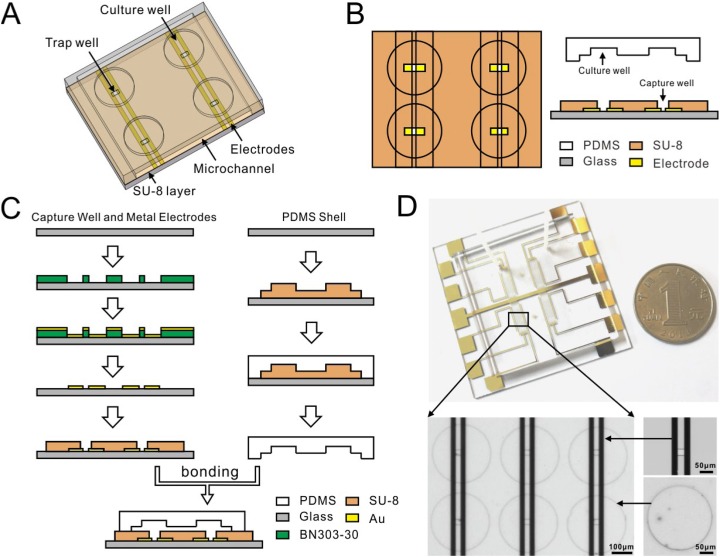
The microfluidic device is composed of upper and lower parts [Fig. 1(a)]. The lower part is used for cell fusion, while the upper part is used for cell culture. The lower part is configured with an array of rectangular trenches termed “capture wells” on interdigital array (IDA) electrodes for cell capture, pairing, and fusion. The upper part consists of an equal number of bigger and round microwells termed “culture wells” for subsequent culture of fused cells. As the key component, the electrode-photoresist structure provides mechanical constriction, electrical field of DEP manipulation, and electrical fusion stimuli, while the polydimethylsiloxane (PDMS) microchannel facilitates solution streaming like PEG stimuli and cell culture. According to the DEP theory, when a cell is located in a nonuniform electric field, polarization charges in the cell would generate a net force, which directs the cell either toward (positive DEP, pDEP)33 or away from (negative DEP, nDEP)34 the electric field maximum. In this design, cell capture-pairing is achieved by using pDEP and “capture wells” on IDA electrodes to trap two single cells [Fig. 1(b)] on the rectangular ends, followed by using nDEP to pair the two cells. From the design perspective, the chip can be configured with an unlimited number of capture-pairing-fusion-culture units. Moreover, the geometric dimensions of the trench can be tailored, according to cell sizes/types and the number of cells to be fused. In this study, the number of units was set to 864 to show the applicability.
FIG. 1.
Device design and fabrication. (a) Sketch of the device structure. (b) Top and side view of the device. (c) Fabrication procedure. (d) Photography of the device showing the electrodes, capture wells, and culture wells. Note the dimensions in (a)–(c) are not to scale.
B. Device fabrication
Figure 1(c) illustrates the fabrication procedure. The gold electrodes on glass were deposited through a standard lift-off process by sputtering gold with a negative photoresist (BN303-30, Kempur Corp., China). A 2 m-thick layer of BN303-30 was then subsequently spin-coated to act as a seeding layer and protect cells from electrodes. Finally, the electrode-photoresist structure was coated with a 25 m-thick layer of a negative photoresist (SU-8), which was photopatterned and developed to form the arrayed capture wells by soft lithography. As for the PDMS layer, we followed the standard mold-replica method, i.e., used a negative photoresist (SU-8) first to obtain a mold patterned with a rather big microchannel (m) and the arrayed culture wells and then poured the PDMS mixture [10:1 (by weight) PDMS base/curing agent] (Sylgard 184, Dow Corning) on the mold. After being cured (80 C, 30 min), the PDMS layer was peeled off and bonded to the electrode-photoresist structure. Oxygen plasma was used to enhance the adhesion of PDMS and SU-8; thus, the two components were assembled firmly. The device was finally washed thoroughly and stored in de-ionized water for use. Figure 1(d) is the photography of the device.
C. Device working procedure
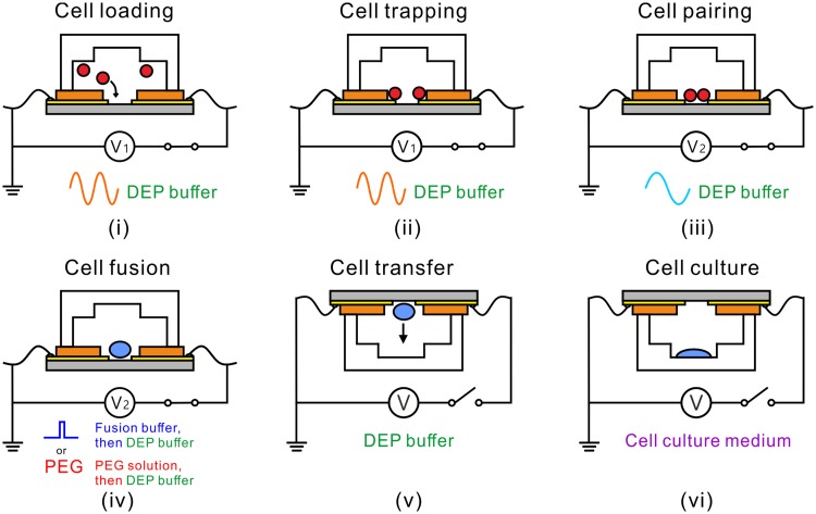
Figure 2 is the working procedure of the device. First, the pDEP force is activated to attract two cells into the trenches, and after the attraction is completed, the cells outside the trenches are washed away by DEP buffer. Under the action of the pDEP force, the two captured cells may not be in good contact, so the nDEP force is then activated to push the two cells toward each other to achieve cell-cell contact (paired cells), which can provide a good fusion condition for the subsequent cell fusion. The paired cells are then fused by electrical pulses or PEG. Once the cells are fused, the device is flipped to transfer the fused cells by gravity22 into culture wells for the cell couplets to spread and grow during cell culture. No matter whether the fusion is successful or not, the cells in each capture well would be transferred to the corresponding culture well. This provides a chance to compare the growth of the fused and unfused cells. After the cells fall into the culture wells, the entire device is placed into the cell culture incubator for several days of culture and observation.
FIG. 2.
The working procedure of the device. (i) Cell loading. (ii) Cell trapping. (iii) Cell pairing. (iv) Cell fusion. (v) Cell transfer. (vi) Cell culture.
The entire experimental procedure is ought to be carried out at C to ensure cell viability.35 In order to prevent the fused cells from adhering to the capture wells, surface modification with bovine serum albumin is required before the lower part of the device is used. The AC signal is configured with high frequency for pDEP trapping and low frequency for nDEP pairing. To stabilize the cell couplet, the nDEP AC signal is held on during cell fusion regardless of the fusion protocol. It is still held on before the device is flipped completely. However, any electrical signal is switched off after device flipping.
Either electrical or chemical means can be used to achieve cell fusion. The difference lies in the fusion stimulus. In electrical fusion, a series of DC pulses are applied to the cell couplet to generate electroporation across the cell membranes at the contact area.36 In chemical means, PEG solution is flushed to the microchannel to initiate cell membrane dehydration-induced pore formation.37 Because cell fusion takes some time to complete, in both methods, the device should be kept still, and the flow rate should be set low to avoid moving the cell couplet.
The solution flowing into the device varies during the whole procedure. Initially, the device is prefilled with standard cell culture medium to avoid bubbles. In cell loading, trapping, and pairing, DEP buffer solution is used. In cell fusion, the solution is switched to fusion buffer (for electrical fusion) or PEG solution (for chemical fusion) during the action of fusion stimuli and then DEP buffer again. In cell transfer, the solution is still the DEP buffer. Finally, in cell culture, standard cell culture medium is used.
Indeed, the device follows the ideas of two works,22,31 which are neat in structure and thus open to additional functional structures and modules with spatiotemporal compatibility. By leveraging this advantage, the device integrates the two modules together so that the two modules can work not only independently as the combination does, but also coordinate to work better as the integration does. In particular, the pDEP force counteracts the adverse effects of the fluidic drag force in cell capture and cell transfer. This improvement may be not so significant, but it is beneficial to increase the overall fusion efficiency.
D. Experimental setup
In the experiment, cells were loaded into the microchannel by pulling the pump (Legato 200, KD Scientific). The microfluidic device was placed on an inverted fluorescence microscope (Nikon ECLIPSE Ti-U) stage equipped with a thermoplate (MATS-U505R30, Tokai Hit), and a camera (Nikon DS-Ri1) was mounted on the microscope for image capture and video recording. AC signals were supplied by a function generator (AFG3052C, Tektronix) and a high frequency signal amplifier (2350, TEGAM).
1. Solution preparation
DEP buffer should have a low conductivity, which can reduce the DEP-induced Joule heating effect. In this work, the DEP buffer was composed of 16% (w/v) sucrose + 2% (w/v) PBS + 82% (w/v) de-ionized water, which had a conductivity of 36.5 mS/m.32,38
Fusion buffer was prepared by mixing cell culture medium with hypotonic buffer containing 0.1 mM Ca acetate, 0.5 mM Mg acetate, and 75 mM sorbitol39 at a mixing ratio of 1:10.2.
PEG solution was made up of equal masses of PEG-1500 (Sigma-Aldrich) and de-ionized water.16
2. Cell preparation
HeLa cells were cultivated at 37 and in a incubator using RPMI 1640 medium supplemented with 10% fetal bovine serum (FBS). Cells were rinsed with PBS twice and then lifted off by treating with trypsin for 5 min. The cell suspension was washed three times by centrifuging at 300g for 5 min, removing the supernatant with a pipette, and resuspending the cell pellet in 1 ml DEP buffer. To facilitate single cell loading, the cell suspension was then diluted with additional DEP buffer for a cell concentration of cells/ml in cell loading.
III. RESULTS AND DISCUSSION
A. Cell trapping and pairing
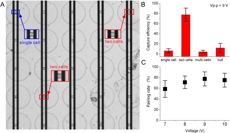
First, we applied the pDEP AC signal to trap cells into the arrayed trenches and then nDEP to pair them. The trenches () were designed according to the size of HeLa cells to reduce the probability of trapping excess cells. From the experiment, AC signals with voltages between 1.2 Vpp and 9 Vpp (i.e., 0.04 KV/cm and 0.3 KV/cm, respectively) and frequencies between 600 kHz and 1 MHz were found operational for cell trapping. Figure 3(a) shows the capture performance ( MHz). Most trench units exactly captured two cells, and a few units captured multiple cells. Figure 3(b) plots the capture efficiency of the device. The capture efficiency for two cells reached 77%, single cell 7%, multiple cells 4%, and empty cells 9%, respectively. Note in this paper, each capture well is expected to capture two cells to form the cell pair in the perfect condition. Therefore, we define the capture efficiency for two cells as pairing efficiency. The pairing efficiency was different under different voltage amplitudes, as shown in Fig. 3(c). Obviously, the higher the voltage was, the higher the pairing efficiency was. For example, when the voltage was 6 Vpp, the pairing efficiency was 70%, whereas when the voltage increased to 9 Vpp, the pairing efficiency rose to 78%. However, when the amplitude exceeded 10 Vpp, the pairing efficiency decreased, probably due to the increasing electrothermal effect.40 In addition, excessive voltage can easily cause cell electroporation (when cell membrane voltage V) and reduce cell viability. Therefore, the voltage used in the experiment was selected as 9 Vpp.
FIG. 3.
Cell capture and pairing results. (a) Cells are captured in the well array. (b) The capture efficiency. (c) The pairing efficiencies under different voltages. Error bars represent the standard deviation for each data set. The sample number .
After trapping, the uncaptured cells landed outside and the captured trenches were washed out. To ensure that the cells captured in the trenches were not washed away, the pDEP AC signal was kept on throughout the washing process and the flow rate was set no more than 30 m/s. Under pDEP, the cells sat apart on both sides of the trench. After washing out the excess cells, the captured cells were paired by changing the AC signal frequency to 100 Hz to generate nDEP forces, which pushed the cells away from the planar electrodes to get in good contact inside the trench. Note that this nDEP AC signal was continuously applied throughout the subsequent fusion process to keep the cell pairs in contact.
B. Cell fusion
Both electrical and chemical protocols could induce cell fusion. In the experiment, we compared the two fusion methods. In electrofusion, a series of short-duration (30–50 ms) and high strength (0.5–2 KV/cm) pulses (3–10 pulses, 0.5 s interval) are normally applied. These parameters are reported optimal by the literature.41–43 In this work, we did not aim to optimize the electrofusion condition. Instead, we just aimed to demonstrate that the electrofusion was workable for this device. Therefore, the pulses we applied specifically were 40 ms duration, 5 pulses, 0.5 s interval, and 2 KV/cm. In the chemical method, the cells were exposed to PEG solution for 1 min, and then DEP buffer was fed in to wash out the PEG solution to prevent the cell membranes from long-term damage.
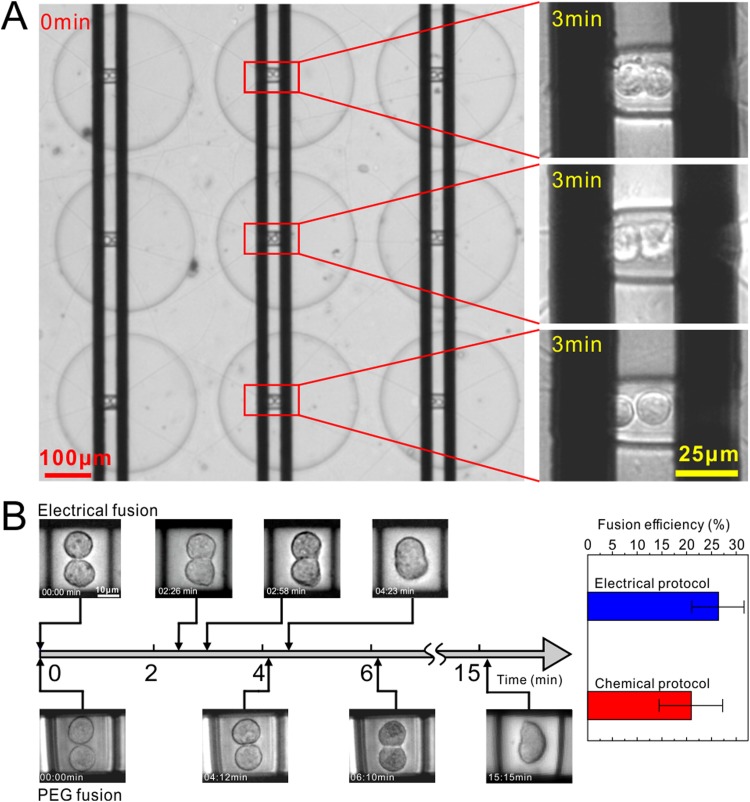
After fusion application, the cell pairs remained intact in situ for up to 15 min to maintain stabilization until the end of the fusion process, which was indicated by complete vanishing of the cell membranes at the contact area. Figure 4(a) shows the fusion states of three units after 3 min of the electric pulse application. Most of the cells in the array began to fuse, but they progressed slightly differently. Figure 4(b) shows the fusion results of electrofusion and PEG as comparison. Both electrofusion and PEG could be applied to our device for successful fusion. However, as many works6,16,44,45 demonstrated, electrofusion was faster than PEG fusion. For example, here, it took 4 min for electrofusion, while 15 min for PEG fusion, nearly 4 times longer to finish. Overall, the efficiency of the electrical fusion method was about 26%, higher than that of the chemical method (21%).
FIG. 4.
Cell fusion results. (a) Cell fusion state in different well arrays under electrical stimuli. The first two paired cells are undergoing fusion successfully, indicated by the fuzzy cell membranes at the contact area. The third cell does not exhibit fusion, indicated by the clear membranes. (b) The cell fusion process reflected by time-lapsed images under electrical and PEG methods and the fusion efficiency.
C. Cell culture
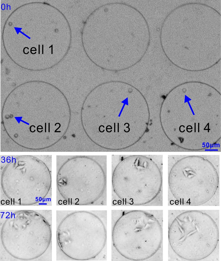
To assess the capability of our device for long-term single-cell culture, the device was flipped gently by hand after the fusion process to transfer the fused cells by gravity into culture wells. To make transfer successful, we followed the practice in the literature22 to seal the inlet and outlet holes before transfer. By doing so, the fluidic microenvironment around the fused cells remained stagnant and the cells kept intact. Almost all (96%) cells were successfully transferred within 5 min, and the solution was switched from DEP buffer to cell culture medium. This solution switch was carefully done to avoid washing cells out of the culture wells. It then took about 30 min for the cells to recover adhesion and started to cultivate. As shown in Fig. 5, initially, both fused and unfused cells were transferred into the culture wells. After 36 h, most cells have attached and spread on the FBS modified PDMS surface.46 Proliferation and migration of cell colonies were observed happening by 72 h only within each well, rather than across the wells. The culture results provide evidence that the fused cells were viable and demonstrate the applicability of our device.
FIG. 5.
On-chip culture of single fused cells. The growth of each fused cell within 72 h can be observed.
IV. CONCLUSIONS
In this paper, we have proposed a microfluidic device for multiprotocol cell fusion and subsequent on-chip culture and demonstrated successful fusion and culture of HeLa cells. Our device yielded 864 homotypic cell pairs with averaged 80% pairing efficiency. Multifusion protocol compatibility makes our device more flexible for cell fusion tasks. The built-in cell culture modality provides favorable conditions for evaluating the growth, proliferation, and migration of single fused cells without interference from colony confluence. Besides, our device is highly adaptable to different tasks since the design for homotypic cells could be easily configured to fuse and culture heterotypic cells.
ACKNOWLEDGMENTS
This work was supported by the NSFC (Nos. 61774095 and 21727813).
There are no conflicts to declare.
REFERENCES
- 1.Kemna E. W., Wolbers F., Vermes I., and van den Berg A., “On chip electrofusion of single human B cells and mouse myeloma cells for efficient hybridoma generation,” Electrophoresis 32, 3138–3146 (2011). 10.1002/elps.201100227 [DOI] [PubMed] [Google Scholar]
- 2.Cowan C. A., Atienza J., Melton D. A., and Eggan K., “Nuclear reprogramming of somatic cells after fusion with human embryonic stem cells,” Science 309, 1369–1373 (2005). 10.1126/science.1116447 [DOI] [PubMed] [Google Scholar]
- 3.Köhler G. and Milstein C., “Continuous cultures of fused cells secreting antibody of predefined specificity,” Nature 256, 495 (1975). 10.1038/256495a0 [DOI] [PubMed] [Google Scholar]
- 4.Lo M. M., Tsong T. Y., Conrad M. K., Strittmatter S. M., Hester L. D., and Snyder S. H., “Monoclonal antibody production by receptor-mediated electrically induced cell fusion,” Nature 310, 792 (1984). 10.1038/310792a0 [DOI] [PubMed] [Google Scholar]
- 5.Gong J., Koido S., and Calderwood S. K., “Cell fusion: From hybridoma to dendritic cell-based vaccine,” Expert Rev. Vaccines 7, 1055–1068 (2008). 10.1586/14760584.7.7.1055 [DOI] [PubMed] [Google Scholar]
- 6.Lindner M. and Schirrmacher V., “Tumour cell—Dendritic cell fusion for cancer immunotherapy: Comparison of therapeutic efficiency of polyethylene-glycol versus electro-fusion protocols,” Eur. J. Clin. Invest. 32, 207–217 (2002). 10.1046/j.1365-2362.2002.00968.x [DOI] [PubMed] [Google Scholar]
- 7.Rosenblatt J., Kufe D., and Avigan D., “Dendritic cell fusion vaccines for cancer immunotherapy,” Expert Opin. Biol. Ther. 5, 703–715 (2005). 10.1517/14712598.5.5.703 [DOI] [PubMed] [Google Scholar]
- 8.Zhang S., Mercado-Uribe I., Xing Z., Sun B., Kuang J., and Liu J., “Generation of cancer stem-like cells through the formation of polyploid giant cancer cells,” Oncogene 33, 116 (2014). 10.1038/onc.2013.96 [DOI] [PMC free article] [PubMed] [Google Scholar]
- 9.Brodbeck W. G. and Anderson J. M., “Giant cell formation and function,” Curr. Opin. Hematol. 16, 53 (2009). 10.1097/MOH.0b013e32831ac52e [DOI] [PMC free article] [PubMed] [Google Scholar]
- 10.Gurdon J. and Melton D., “Nuclear reprogramming in cells,” Science 322, 1811–1815 (2008). 10.1126/science.1160810 [DOI] [PubMed] [Google Scholar]
- 11.Lu X. and Kang Y., “Cell fusion as a hidden force in tumor progression,” Cancer Res. 69, 8536–8539 (2009). 10.1158/0008-5472.CAN-09-2159 [DOI] [PMC free article] [PubMed] [Google Scholar]
- 12.Wang X., Willenbring H., Akkari Y., Torimaru Y., Foster M., Al-Dhalimy M., Lagasse E., Finegold M., Olson S., and Grompe M., “Cell fusion is the principal source of bone-marrow-derived hepatocytes,” Nature 422, 897 (2003). 10.1038/nature01531 [DOI] [PubMed] [Google Scholar]
- 13.Hu N., Yang J., Joo S. W., Banerjee A. N., and Qian S., “Cell electrofusion in microfluidic devices: A review,” Sens. Actuators B Chem. 178, 63–85 (2013). 10.1016/j.snb.2012.12.034 [DOI] [Google Scholar]
- 14.Zhao S., He W., Ma Z., Liu P., Huang P.-H., Bachman H., Wang L., Yang S., Tian Z., Wang Z. et al., “On-chip stool liquefaction via acoustofluidics,” Lab Chip 19, 941–947 (2019). 10.1039/C8LC01310A [DOI] [PMC free article] [PubMed] [Google Scholar]
- 15.Dura B. and Voldman J., “Microfluidic systems for cell pairing and fusion,” in Cell Fusion (Springer, 2015), pp. 73–94. [DOI] [PubMed]
- 16.Skelley A. M., Kirak O., Suh H., Jaenisch R., and Voldman J., “Microfluidic control of cell pairing and fusion,” Nat. Methods 6, 147 (2009). 10.1038/nmeth.1290 [DOI] [PMC free article] [PubMed] [Google Scholar]
- 17.Wang X., Chen S., Chow Y. T., Kong C.-w., Li R. A., and Sun D., “A microengineered cell fusion approach with combined optical tweezers and microwell array technologies,” RSC Adv. 3, 23589–23595 (2013). 10.1039/c3ra44108c [DOI] [Google Scholar]
- 18.Qu Y., Hu N., Xu H., Yang J., Xia B., Zheng X., and Yin Z. Q., “Somatic and stem cell pairing and fusion using a microfluidic array device,” Microfluid. Nanofluidics 11, 633–641 (2011). 10.1007/s10404-011-0829-y [DOI] [Google Scholar]
- 19.Kirschbaum M., Guernth-Marschner C. R., Cherré S., de Pablo Peña A., Jaeger M. S., Kroczek R. A., Schnelle T., Mueller T., and Duschl C., “Highly controlled electrofusion of individually selected cells in dielectrophoretic field cages,” Lab Chip 12, 443–450 (2012). 10.1039/C1LC20818G [DOI] [PubMed] [Google Scholar]
- 20.Ju J., Ko J.-M., Cha H.-C., Park J. Y., Im C.-H., and Lee S.-H., “An electrofusion chip with a cell delivery system driven by surface tension,” J. Micromech. Microeng. 19, 015004 (2008). 10.1088/0960-1317/19/1/015004 [DOI] [Google Scholar]
- 21.Huang L., Chen Y., Huang W., and Wu H., “Cell pairing and polyethylene glycol (PEG)-mediated cell fusion using two-step centrifugation-assisted single-cell trapping (CAScT),” Lab Chip 18, 1113–1120 (2018). 10.1039/C7LC01131H [DOI] [PubMed] [Google Scholar]
- 22.Lin C.-H., Hsiao Y.-H., Chang H.-C., Yeh C.-F., He C.-K., Salm E. M., Chen C., Chiu M., and Hsu C.-H., “A microfluidic dual-well device for high-throughput single-cell capture and culture,” Lab Chip 15, 2928–2938 (2015). 10.1039/C5LC00541H [DOI] [PubMed] [Google Scholar]
- 23.Park T. H. and Shuler M. L., “Integration of cell culture and microfabrication technology,” Biotechnol. Prog. 19, 243–253 (2003). 10.1021/bp020143k [DOI] [PubMed] [Google Scholar]
- 24.Karatekin E. and Rothman J. E., “Fusion of single proteoliposomes with planar, cushioned bilayers in microfluidic flow cells,” Nat. Protoc. 7, 903 (2012). 10.1038/nprot.2012.019 [DOI] [PMC free article] [PubMed] [Google Scholar]
- 25.Estes D. J., Lopez S. R., Fuller A. O., and Mayer M., “Triggering and visualizing the aggregation and fusion of lipid membranes in microfluidic chambers,” Biophys. J. 91, 233–243 (2006). 10.1529/biophysj.105.076398 [DOI] [PMC free article] [PubMed] [Google Scholar]
- 26.Rems L., Ušaj M., Kandušer M., Reberšek M., Miklavčič D., and Pucihar G., “Cell electrofusion using nanosecond electric pulses,” Sci. Rep. 3, 3382 (2013). 10.1038/srep03382 [DOI] [PMC free article] [PubMed] [Google Scholar]
- 27.Robinson T., Verboket P. E., Eyer K., and Dittrich P. S., “Controllable electrofusion of lipid vesicles: Initiation and analysis of reactions within biomimetic containers,” Lab Chip 14, 2852–2859 (2014). 10.1039/c4lc00460d [DOI] [PubMed] [Google Scholar]
- 28.Yang J., Zhao L.-P., Yin Z.-Q., Hu N., Chen J., Li T.-Y., Svir I., and Zheng X.-L., “Chip-based cell electrofusion,” Adv. Eng. Mater. 12, B398–B405 (2010). 10.1002/adem.200980063 [DOI] [Google Scholar]
- 29.Hu N., Yang J., Qian S., Zhang X., Joo S. W., and Zheng X., “A cell electrofusion microfluidic chip using discrete coplanar vertical sidewall microelectrodes,” Electrophoresis 33, 1980–1986 (2012). 10.1002/elps.201100579 [DOI] [PubMed] [Google Scholar]
- 30.Dura B., Liu Y., and Voldman J., “Deformability-based microfluidic cell pairing and fusion,” Lab Chip 14, 2783–2790 (2014). 10.1039/c4lc00303a [DOI] [PubMed] [Google Scholar]
- 31.Şen M., Ino K., Ramón-Azcón J., Shiku H., and Matsue T., “Cell pairing using a dielectrophoresis-based device with interdigitated array electrodes,” Lab Chip 13, 3650–3652 (2013). 10.1039/c3lc50561h [DOI] [PubMed] [Google Scholar]
- 32.Huang L., He W., and Wang W., “A cell electro-rotation micro-device using polarized cells as electrodes,” Electrophoresis 40, 784–791 (2019). 10.1002/elps.201800360 [DOI] [PubMed] [Google Scholar]
- 33.Voldman J., “Electrical forces for microscale cell manipulation,” Annu. Rev. Biomed. Eng. 8, 425–454 (2006). 10.1146/annurev.bioeng.8.061505.095739 [DOI] [PubMed] [Google Scholar]
- 34.Thomas R. S., Morgan H., and Green N. G., “Negative DEP traps for single cell immobilisation,” Lab Chip 9, 1534–1540 (2009). 10.1039/b819267g [DOI] [PubMed] [Google Scholar]
- 35.Frey S., Marsh M., Günther S., Pelchen-Matthews A., Stephens P., Ortlepp S., and Stegmann T., Temperature dependence of cell-cell fusion induced by the envelope glycoprotein of human immunodeficiency virus type 1,” J. Virology 69, 1462–1472 (1995). [DOI] [PMC free article] [PubMed] [Google Scholar]
- 36.Tresset G. and Takeuchi S., “A microfluidic device for electrofusion of biological vesicles,” Biomed. Microdevices 6, 213–218 (2004). 10.1023/B:BMMD.0000042050.95246.af [DOI] [PubMed] [Google Scholar]
- 37.Lentz B. R., “Polymer-induced membrane fusion: Potential mechanism and relation to cell fusion events,” Chem. Phys. Lipids 73, 91–106 (1994). 10.1016/0009-3084(94)90176-7 [DOI] [PubMed] [Google Scholar]
- 38.Huang L., Zhao P., and Wang W., “3D cell electrorotation and imaging for measuring multiple cellular biophysical properties,” Lab Chip 18, 2359–2368 (2018). 10.1039/C8LC00407B [DOI] [PubMed] [Google Scholar]
- 39.van der Bosch J., Schudt C., and Pette D., “Influence of temperature, cholesterol, dipalmitoyllecithin and Ca on the rate of muscle cell fusion,” Exp. Cell Res. 82, 433–438 (1973). 10.1016/0014-4827(73)90362-5 [DOI] [PubMed] [Google Scholar]
- 40.Park S., Koklu M., and Beskok A., “Particle trapping in high-conductivity media with electrothermally enhanced negative dielectrophoresis,” Anal. Chem. 81, 2303–2310 (2009). 10.1021/ac802471g [DOI] [PubMed] [Google Scholar]
- 41.Stenger D., Kubiniec R., Purucker W., Liang H., and Hui S., “Optimization of electrofusion parameters for efficient production of murine hybridomas,” Hybridoma 7, 505–518 (1988). 10.1089/hyb.1988.7.505 [DOI] [PubMed] [Google Scholar]
- 42.Guo W., Deng X., and Shi Y., “Optimization of electrofusion parameters and interspecific somatic hybrid regeneration in citrus,” Acta Bot. Sin. 40, 417–424 (1998). [Google Scholar]
- 43.Saunders J. A., Lin C. H., Hou B. H., Cheng J., Tsengwa N., Lin J. J., Smith C. R., McIntosh M. S., and Van Wert S., “Rapid optimization of electroporation conditions for plant cells, protoplasts, and pollen,” Mol. Biotechnol. 3, 181–190 (1995). 10.1007/BF02789328 [DOI] [PubMed] [Google Scholar]
- 44.San L. H., Vedel F., Sihachakr D., and Rémy R., Morphological and molecular characterization of fertile tetraploid somatic hybrids produced by protoplast electrofusion and PEG-induced fusion between Lycopersicon esculentum Mill. and Lycopersicon peruvianum Mill.,” Mol. Gen. Genet. 221, 17–26 (1990). 10.1007/BF00280362 [DOI] [Google Scholar]
- 45.Assani A., Chabane D., Haïcour R., Bakry F., Wenzel G., and Foroughi-Wehr B., “Protoplast fusion in banana (Musa spp.): Comparison of chemical (PEG: polyethylene glycol) and electrical procedure,” Plant Cell Tissue Organ Cult. 83, 145–151 (2005). 10.1007/s11240-005-4633-9 [DOI] [Google Scholar]
- 46.Whulanza Y., Nadhif H., Istiyanto J., Supriadi S., and Bachtiar B., “PDMS surface modification using biomachining method for biomedical application,” J. Biomim. Biomater. Biomed. Eng. 26, 66–72 (2016). 10.4028/www.scientific.net/JBBBE.26.66 [DOI] [Google Scholar]


