Abstract
Molecular docking of peptides to proteins can be a useful tool in the exploration of the possible peptide binding sites and poses. CABS‐dock is a method for protein–peptide docking that features significant conformational flexibility of both the peptide and the protein molecules during the peptide search for a binding site. The CABS‐dock has been made available as a web server and a standalone package. The web server is an easy to use tool with a simple web interface. The standalone package is a command‐line program dedicated to professional users. It offers a number of advanced features, analysis tools and support for large‐sized systems. In this article, we outline the current status of the CABS‐dock method, its recent developments, applications, and challenges ahead.
Keywords: molecular modeling, peptide drugs, peptide therapeutics, protein–peptide complex, protein–peptide interactions, structure prediction
1. INTRODUCTION
Peptide drug discovery is currently a very active research field with great potential for addressing unmet medical needs.1, 2, 3 The vast array of new technologies is being employed to facilitate the discovery of new peptide‐based drugs, including those aiming at the structural characterization of peptide interactions with their protein targets. Since the experimental characterization can be difficult, or costly and time‐consuming, computational methods have become important supporting tools and in many cases an attractive alternative. In recent years, a variety of computational tools have been developed for docking of peptides to proteins,4 that is, prediction of the three‐dimensional structures of the protein–peptide complexes. Protein–peptide docking methods can be divided into three categories4: template‐based docking, local docking, and global docking techniques. Generally, the template‐based docking uses known structures of the receptor–peptide complexes as scaffolds, the local docking is limited to the predefined binding site, while the global docking tools are designed to search for both the binding site and the peptide pose. CABS‐dock is a global docking method that we introduced in 2015 as a web server5 (available at http://biocomp.chem.uw.edu.pl/CABSdock). Motivated by a large number of users and their various demands, in 2018 we presented the standalone version6 (available at http://bitbucket.org/lcbio/cabsdock/). While the web server is dedicated to quick and easy setup of docking simulations and browsing of modeling results, the standalone version is designed for power users interested in the most advanced feature set.
The central module of the CABS‐dock method is its fast simulation engine: the CABS coarse‐grained protein model. It has proven to be an extremely efficient tool in many applications.7 It allows for modeling of the long timescale conformational rearrangements of polypeptide chains, like the process of peptide folding and its simultaneous binding to the flexible protein receptor in a single CABS‐dock simulation run. It has been estimated that in terms of the computational efficiency the CABS model surpasses Molecular Dynamics speed by about three to four orders of magnitude.8 The natural cost of such a speedup is loss of accuracy, which has been mostly averted thanks to the clever design of the protein representation. Thanks to the sampling efficiency, the CABS‐dock offers a unique opportunity for on‐the‐fly simulation of the flexibility of peptide and protein receptor molecules during the search for the binding site (other methods rather rely on rigid docking that is sometimes merged with the next step of flexible refinement4, 9, 10, 11, 12). The CABS model representation, interaction, and sampling schemes are briefly described in the next section. On top of the CABS model, the CABS‐dock tool has been designed primarily to address the problem of the protein–peptide docking, but also to encapsulate the raw CABS procedures within a user‐friendly interface. Our intent was to make the CABS model usable by a wide group of scientists, who could tailor the simulation setup and conditions directly to their needs. The most prospective way to achieve this aim is by the skillful application of the available distance restraints, as demonstrated in this article. In the “CABS‐dock method” section, we describe the current status of the CABS‐dock tool, its design and its major features. Over the past few years, the CABS‐dock applications have been presented in a series of publications.5, 6, 13, 14, 15, 16, 17, 18, 19 Those are briefly discussed in the “CABS‐dock applications” section together with the remaining challenges and potential ways of addressing these issues.
2. THE CABS MODEL
CABS—a coarse‐grained model of protein structure, interactions, and dynamics (see review by Kmiecik et al.7) is utilized by the CABS‐dock method as a simulation engine. The CABS (name comes from the names of pseudo‐atoms: C‐Alpha, C‐Beta and the Side‐chain) representation of protein backbone is reduced to just two pseudo‐atoms per single residue, one representing the center of the alpha‐carbon and another one placed at the center of the C‐alpha—C‐alpha pseudo‐bond (Figure 1). Side chains in the CABS structures are replaced by at most two pseudo‐atoms per residue, one representing the C‐beta atom and one placed at the center of the remaining (where applicable) portion of the amino acid side chain. Positions of the C‐alpha pseudo‐atoms are discretized by a dense underlying lattice. Such discretization has no noticeable influence on the model properties while it greatly simplifies computations, allowing for larger‐scale simulations than other equivalent continuous models do. The shape of the main chain defines the position of the side chains—the model assumes a single rotamer representation of a side chain, dependent however on the local conformation of the main chain. Certainly, this simplification has some influence on the resolution of the CABS representation, although it significantly accelerates the simulation process. The average resolution of the CABS models, measured as the RMSD, is better than 1 Å for C‐alpha‐traces and fluctuates between 1 Å and 2 Å for all‐atom structures (Figure 1).
Figure 1.
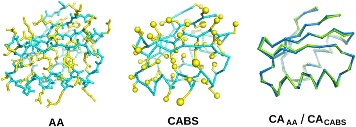
Representation of the three‐dimensional structure of the α + β type 2‐layer sandwich protein (PDB ID: 3IWL). The first panel shows all‐atom (AA) structure. The second panel shows a model in the CABS representation. For both cases, side‐chain atoms are shown in yellow (for CABS—the C‐beta atom and the united side‐chain pseudo‐atom) while the backbone is shown in cyan. The third panel shows the superposition of the alpha carbons from the CABS model (blue) and the experimental structure (green)
The CABS model uses a specific, knowledge‐based parameterization of the molecular interactions. It consists of several statistical potentials describing the excluded volumes of the united atoms, a model of the main chain hydrogen bonds and the contact potentials of the side chains.7, 20, 21 The interactions of the side chains are context‐dependent and are derived from the statistical analysis of known protein structures. The average effects of the solvent are treated in an implicit fashion and hidden within the contact potentials. Details of the CABS force field design can be found in our earlier publications.7, 20, 21 The statistical potentials impose specific limits on the transferability of the CABS force field. In its present form, it cannot be applied to nonprotein systems, for instance for modeling of the RNA–protein interactions. However, thanks to the structural variety of the available protein structures the model is quite robust in simulations of the globular proteins, the protein–peptide complexes, and the membrane proteins after a minor modification of the contact potentials.22 CABS and related models using statistical force fields have proven to be the most efficient in computational prediction of the protein structures, not only as supporting tools in case of difficult comparative modeling but also in de novo structure modeling.7
In the CABS model, the sampling of the conformational space is controlled by the Monte Carlo (MC) dynamics protocol, enhanced by the replica‐exchange method. The MC‐dynamics scheme consists of long random sequences of local moves, changing positions of single amino acids or short fragments of polypeptide chains.7 While single moves reproduce specific local conformational transitions their consecutive and random sequences mimic long‐timescale rearrangements. Therefore CABS can be also used for quite realistic simulations of large conformational transitions, including protein folding,23, 24, 25 modeling of the flexibility of the globular proteins8, 26, 27 and also their intrinsically disordered regions.21 Obviously, the coarse‐graining of the structure representation, along with the Monte Carlo model of the dynamics makes CABS inappropriate for studies of subtle effects of the atomistic details. However, the large‐scale effects of the chain geometric restrictions and averaged interactions seem to be treated satisfactorily.7, 20, 21
3. CABS‐DOCK METHOD
CABS‐dock was initially built as an extension of the original CABS model in an attempt to address the protein–protein docking problem. Meanwhile, it has proven to be an effective tool in the protein–peptide docking tasks, which shifted the development process towards the latter. The original objective is still being pursued and will be published in due course. The main thought behind the CABS‐dock design was to allow for a simple and straightforward set up of docking simulation while operating in the default mode, but also providing advanced features and recipes in the form of multiple simulation options for more sophisticated applications. In the default mode, the peptide docking with CABS‐dock requires only the three‐dimensional structure of the protein receptor and amino acid sequence of the peptide ligand. The docking procedure involves five stages (Figure 2): (a) preparation of the initial structures of the receptor protein and the peptide ligand; (b) generation of the specific (extra‐ and intra‐molecular) distance restraints; (c) docking simulation with the CABS coarse‐grained model; (d) selection of the final models; and (e) reconstruction of the final models to all‐atom representation.
Figure 2.
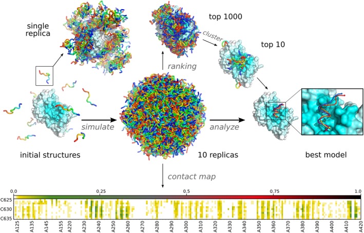
Molecular visualizations of the CABS‐dock docking pipeline. Starting random peptide structures are shown on the left (initial structures). The central part of the figure shows all 10,000 generated models of the protein–peptide complex (10 replicas of the protein–peptide system each containing 1,000 models). In the top left sampling of the conformational space within a single replica is shown. Top 1,000 models are obtained by ranking all models by their binding energy. Clustering is used to choose the top 10 models, which are reconstructed to all‐atom representation. The best‐obtained model is zoomed and compared with the experimental structure (orange). Contact frequency maps are automatically generated from all sets of structures (replicas, clusters, models). The Figure shows docking predictions for the Vitamin D Receptor ligand‐binding domain and coactivator peptide (PDB ID of the protein–peptide complex: 1RJK, the command to run the presented simulation in CABS‐dock standalone is provided in the last section: Examples of CABS‐dock standalone commands)
3.1. CABS‐dock default mode
Initial complexes are generated from the input structure of the protein receptor and the peptide sequence provided by the user. First, the protein receptor structure is converted to the CABS coarse‐grained representation. Next, random peptide structures are randomly selected from a library of generic peptide conformations and placed in random positions around the receptor, in the approximate distance of 20 Å from the receptor surface (Figure 2). Such prepared 10 structures are used as unique starting conformations in each of the 10 replicas of the Replica Exchange Monte Carlo Scheme.
Restraints imposed on the receptor are required to prevent the unfolding of the protein upon peptide docking. They are generated from the initial receptor coordinates submitted by the user. Two residues are automatically restrained if two conditions are met. They need to be at least five residues away from each other along the backbone and the distance between their C‐alpha atoms must be within the range of 5–15 Å (Figure 3). Such restraints usually allow for fluctuations of the C‐alpha trace in the range of 1 Å; and consequently, for larger fluctuations of side‐chain positions. Larger backbone fluctuations can be achieved through careful modification of the default restraints scheme (see section 3.3) or through applying other restraints schemes available in the standalone application. The simulation of protein dynamics in the CABS model is conducted using a Replica Exchange Monte Carlo pseudo‐dynamics with simulated annealing. In the default mode, 10 replicas and 20 annealing cycles are used. Such a sampling scheme allows for docking of fully flexible peptides (or small proteins) to flexible proteins, allowing also for large‐scale conformational transitions of the receptor fragments, in a reasonable computational time.
Figure 3.
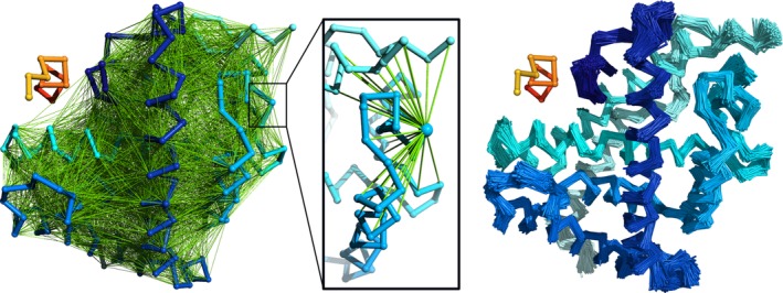
Distance restraints imposed on the protein receptor in the CABS‐dock default mode. The left panel shows the complete network of restraints. In the middle, the restraints for a single residue are shown. The right panel shows 1,000 models of the receptor collected in a single CABS‐dock run. In orange/red the peptide chain is shown for reference
Trajectories are collected from all 10 replicas, however, only a small fraction of the generated models is saved, resulting in 1,000 models for each replica, thus 10,000 models in total. Model selection is a three‐step procedure. First, from the initial 10,000 models, all nonbinding modes are filtered out. The remaining collection is ordered by the protein–peptide interaction energy and the lowest 10% of them is jointly clustered in a k‐medoids procedure (k = 10). The distance between models is measured as the RMSD calculated on the peptide C‐alpha atoms after complex superposition based on receptor coordinates only. Clusters' medoids are considered the final models and the cluster size is used as a ranking parameter. The final reconstruction of the protein–peptide complexes to all‐atom representation complexes is done using the MODELLER tool.19
3.2. CABS‐dock options
CABS‐dock is equipped with a number of options that allow for deviation from its default mode of operation. Selected options were already introduced in the web server version, but their broadest palette was provided in the standalone package. Apart from typical settings controlling the parameters of the simulation such as its length (number of MC cycles), simulation temperature and initial conditions, CABS‐dock provides numerous options that can adjust the docking process to specific applications. In the next two paragraphs, we briefly discuss distance restraints and excluding options, which can be used to control the extent of conformational sampling during the docking simulation.
3.3. Distance restraints
CABS‐dock provides a sophisticated interface to add, remove, and modify arbitrary distance restraints. They can be attached either to the C‐alpha atoms or to the side chain pseudo‐atoms, both within a single and across multiple protein chains, including the peptide. The restraints are characterized by their equilibrium distance and the slope at which the energetic penalty increases when restraints are violated. The C‐alpha—C‐alpha restraints potential has a shape of a trapeze well, with a 1 Å tolerance around the equilibrium distance and evenly sloped sides. The side‐chain restraints are treated differently—they act more as attractors to pull two residues together rather than a scaffold. In such a case, the penalty for violating the restraint is only imposed if the distance between restrained side chains is greater than the equilibrium length. A detailed description of the restraints scheme can be found here.28
Through careful modification of the automatically generated restraints, it is possible to assign various levels of flexibility to selected regions of the receptor molecule. For example, the intrinsically disordered regions in protein receptor14 or flexible loops13 can be modeled with the CABS‐dock by removing respective restraints. Also, the removal of the cross‐chain restraints within the receptor may allow simulating the relative movement of protein domains. Completely disabling protein restraints is a way to model de novo simultaneous folding and binding.
3.4. Excluding
CABS‐dock provides a unique feature to exclude some regions of the receptor from being scanned for potential binding with the peptide. Therefore, other regions, which are known or suspected to bind with a peptide, can be sampled more efficiently.13 This feature can be especially useful when the receptor has multiple binding sites and only some of them are supposed to be examined.
3.5. System size limitations
CABS‐dock standalone is designed to work with peptides consisting of up to 50 residues. This is an arbitrary choice dictated by the design of the protocol, which generates starting conformations. This protocol utilizes a library of random structures of a 50‐amino‐acid‐long polyalanine, which can be easily substituted with an analogous library of a longer polypeptide, thus allowing for larger peptides. Other than that, the number and the size of the protein chains to be modeled are limited only by computer memory. The receptor may consist of multiple chains and the number of peptides to be docked can be greater than one. For practical reasons, in the CABS‐dock web server, the maximum size of a single receptor chain was limited to 500 and the size of the peptide to 30 residues.
3.6. Output analysis and CABS‐dock documentation
The CABS‐dock web server was equipped with some output analysis features that were documented in our recent publications5, 13 and online at the web server website: http://biocomp.chem.uw.edu.pl/CABSdock. The CABS‐dock web server features were extended by the tutorial for analysis and visualization of the CABS‐dock results using VMD software13; simulation contact maps15 and the tutorial for operating the CABS‐dock web server from the command line or the command line scripts.15 In comparison to the web server version, the CABS‐dock standalone package provided many additional analysis features that were summed up by Kurcinski et al.6 and are fully documented at the repository website: http://bitbucket.org/lcbio/cabsdock/. The protocols for the all‐atom reconstruction of CABS‐dock models from C‐alpha trace and their further refinement were described in the recent publication.19
4. CABS‐DOCK APPLICATIONS
4.1. Docking without information about the binding site
The performance of the CABS‐dock modeling protocol was verified in the global docking experiment (using default settings and assuming no information about the binding site or the peptide structure). The tests were run over the PeptiDB dataset29 of nonredundant protein–peptide complexes, including 103 bound and 68 unbound docking cases. As presented in our works,5, 13 high or medium quality models were obtained for 84% of the bound dataset cases (high accuracy—50%, medium accuracy—34%) and for 85% of the unbound dataset cases (high accuracy—35%, medium accuracy—50%) in the sets of 10,000 predicted models. CABS‐dock protocol further narrows the set of 10,000 models to the final 10 top‐scored structures. When only these are considered, high and medium quality models were obtained for 53% of the bound (high—13%, medium—40%) and for 37% of the unbound cases (high—10%, medium—27%). Initial tests included also a demonstration of successful cases using advanced web server options that enable the increase of the range of flexibility for selected receptor fragments or the exclusion of user‐selected binding modes from docking search, see work by Blaszczyk et al.13
4.2. Docking using information about protein–peptide contact(s)
CABS‐dock docking procedure was recently extended by the protocol that enables the usage of the information about protein–peptide contact(s).16 The protocol was made available both as the new feature of the CABS‐dock web server and in the standalone package. The contact information can be used to narrow down the search for the binding peptide pose to the proximity of the binding site, as presented in Figure 4. The figure shows the comparison between docking predictions performed without and including information about single residue‐residue contact. As demonstrated on the PeptiDB benchmark set,16 the contact information significantly improves CABS‐dock performance in comparison to docking without information about the binding interface. Technically, CABS‐dock uses contact information as distance restraint(s) between the centers of mass of the side‐chain pseudo‐atoms with user‐defined restraint distance and weight (see details in the work by Blaszczyk et al.16). Therefore, the accuracy of contact information is controlled by the restraint parameters and even approximate data can be used in the CABS‐dock modeling procedures (see the example in the next “Docking of peptides to GPCR's” section).
Figure 4.
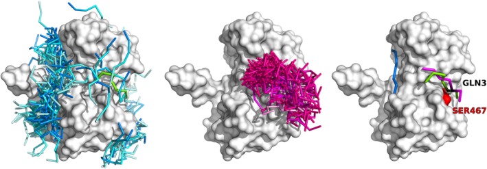
Docking without and with contact information. The Figure shows an example case from the work by Blaszczyk et al.16 of docking LMP1 peptide to TRAF domain (PDB ID: 1CZY). Left panel shows 1,000 top‐scored models from docking without contact information, central panel shows 1,000 top‐scored models from docking with information about the single protein–peptide contact (between SER467 of the protein and GLN3 of the peptide), the right panel shows the best accuracy models form the set of 10 top‐scored models (the SER467 residue is marked in red on the protein receptor surface, the GLN3 peptide residue is marked in black). Peptides models are colored according to the origin: from docking without contact information in blue, with contact information in magenta, the experimental structure (PDB ID: 1CZY) in green. The commands to run the presented simulations in CABS‐dock standalone are provided in the last section: “Examples of CABS‐dock standalone commands”
4.3. Docking of peptides to GPCRs
G‐protein‐coupled receptors (GPCRs) are transmembrane protein receptors that are important targets for peptide‐based drug development.30 Due to experimental difficulties, the number of experimentally determined peptide‐bond GPCR structures is very limited.30 Therefore there is a large need for the structural characterization of new GPCR–peptide interactions that may serve as templates for the design of new GPCRs ligands. Because GPCRs are transmembrane receptor proteins, they have a large hydrophobic surface which is surrounded by a lipid bilayer. In the present version, the CABS‐dock method is dedicated for docking of peptides to globular proteins, therefore peptides are allowed to encounter interactions with the entire receptor surface. In order to prevent peptide binding to the transmembrane domain of the receptor protein (part of the receptor surface engaged in receptor‐membrane interactions), distance restraints between receptor and docked peptide may be imposed to limit sampling the conformational space of a peptide to the neighborhood of extracellular fragments of a GPCR. In addition, internal distance restraints may be also used to mimic disulfide bonds present in docked peptides. We tested this strategy using the GPCR structure from the endothelin ETB receptor–peptide complex (PDB ID: 5GLH 31) and the sequence of the 21‐amino‐acid peptide as the CABS‐dock input. As demonstrated in Figure 5, predicted peptide binding modes are similar to those observed in the crystal structure. Another way of handling GPCR structures in CABS‐dock modeling may be an extension of the CABS model force field to simulate the effect of the biological membrane environment. Originally CABS, and specifically its force field, has been designed for modeling of globular proteins submerged in “averaged” polar solvent. A slight modification of the strength of contact potentials for united atoms representing the amino‐acid side chains allows useful simulations of membrane proteins using the CABS model, as we demonstrated in folding simulations of small membrane proteins.22 This approach is currently tested and will be published in due course. Finally, it is worth to mention that the CABS model has been also successfully used for modeling the structure and dynamics of the second extracellular loop in GPCRs.32 Therefore, the CABS‐dock approach offers promising perspectives for the simulation of long‐timescale conformational dynamics of extracellular loops during docking to GPCRs.
Figure 5.
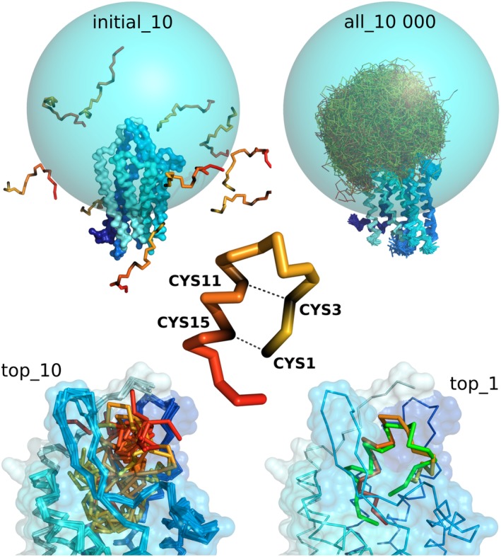
Main stages of CABS‐dock docking procedure used in prediction of an example peptide–GPCR complex. The figure shows the case of endothelin ETB receptor–peptide complex (PDB ID: 5GLH 31). The sampling of a peptide conformational space was limited to the sphere (marked in blue) covering the binding site and extracellular fragments of the GPCR. The sampling was limited using long‐distance restraints (of length 30 Å) between C‐alpha atom of a single GPCR residue (residue number 249) and all C‐alpha atoms of the docked peptide. Additionally, distance restraints were put within the peptide structure to enforce disulfide bridges (cysteine residues number 1–15 and 3–11). In the bottom, the figure shows 10 top‐scored models and first top‐scored model superimposed on the experimental structure shown in green (RMSD value: 3.25 Å). The command to run the presented simulation in CABS‐dock standalone is provided in the last section: Examples of CABS‐dock standalone commands
4.4. High‐resolution structure refinement of CABS‐dock models
Practical applications of docking predictions require structure characterization at the atomic level. The resulting 10 top‐scored models from the CABS‐dock docking are by default reconstructed to all‐atom representation using MODELLER software.19 An additional improvement of CABS‐dock predictions is possible using structure refinement techniques. One of them, the RosettaFlexPepDock protocol,33 has demonstrated excellent performance in many refinement studies of protein–peptide complexes.9, 34, 35 In our work by Badaczewska et al.,19 we describe the protocol for the refinement of CABS‐dock models using the RosettaFlexPepDock. Figure 6 shows examples of several CABS‐dock predictions (for complexes of varying peptide length and secondary structure content) and their refinement results using the RosettaFlexPepDock. As demonstrated in Figure 6, the refinement enables the significant improvement of CABS‐dock models accuracy, including backbone and side‐chain positions.
Figure 6.
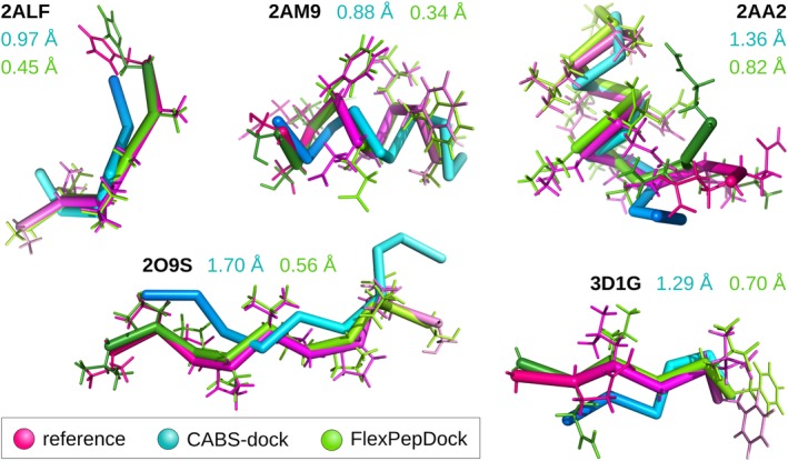
Comparison of CABS‐dock predictions before and after FlexPepDock refinement with experimental structures. The figure presents five examples of protein–peptide complexes (2ALF, 2AM9, 2AA2, 2O9S, and 3D1G). For each complex, only peptide conformations are shown (after superimposition of the receptor structures). CABS‐dock models after MODELLER (Cα to all‐atom) reconstruction are shown in blue and after FlexPepDock refinement in green, while reference experimental structures are pink. The numbers in the corresponding colors indicate i‐RMSD values (interface root mean square deviation from the reference experimental structure)
4.5. Modeling folding and binding dynamics
In addition to structure prediction applications, the CABS‐dock method can be used to simulate dynamics of peptide folding and binding mechanisms14, 18 (the applicability of the CABS force‐field to model protein dynamics has been reviewed elsewhere7, 21). The CABS‐dock methodology was used to simulate the folding and binding of 28‐residue pKID disordered peptide to the KIX protein.18 The KID peptide was simulated as fully flexible (no knowledge about peptide binding site or structure was used) while the receptor backbone was limited to near‐native fluctuations. The simulations resulted in the ensemble of transient encounter complexes in good agreement with experimental results, the example simulation snapshots are presented in Figure 7. The key folding and binding step was linked to the formation of the specific interactions between a preformed native‐like peptide fragment and the receptor surface. In another work by Ciemny et al.,14 the CABS‐dock method was applied to model large‐scale structural rearrangements of MDM2 flexible regions and the role of the disordered 27‐residue MDM2 fragment in the p53 binding. Without a priori knowledge of the p53 peptide structure, or its binding site, we obtained close to experimental models of the p53‐MDM2. The simulation results agreed well with available experimental data and provided new insights into the possible role of the disordered MDM2 fragment in the p53 binding.
Figure 7.
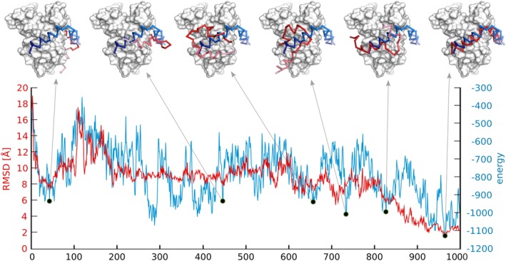
Analysis of a single pseudo‐trajectory (from a single replica) from the CABS‐dock simulation of the KIX‐pKID system.18 The x‐axis represents the simulation progress. Horizontal axes show peptide (pKID) root mean square deviation (RMSD) and total energy fluctuations. Structures corresponding to the local energetic minima are shown above the plot. The KIX receptor is shown in the gray surface, pKID simulated structure in red and pKID experimental pose in blue
As demonstrated in the above‐cited studies, one of the useful CABS‐dock analysis features is simulation contact maps15 (an example map is presented in Figure 2). The maps show the frequency of protein–peptide contacts during folding and binding simulations and can be used to infer the role of particular protein–peptide interactions into the binding process. Presently, in our laboratories, we apply CABS‐dock standalone to model dynamics of peptide aggregates or proteolysis process. Appropriate system setup, and using experimental data in the form of distance restraints, allows us to get an interesting insight into the complex dynamics of these systems and the results will be published soon.
4.6. Modeling protein–protein interactions
Although the CABS‐dock method is dedicated primarily to docking of peptides to proteins, the method allows also for modeling protein–protein interactions. This is possible using the CABS‐dock standalone package.6 As mentioned in the section “System size limitations,” the CABS‐dock standalone currently has the limitation of the peptide size up to 50 residues. This limitation considers only the procedure of generating starting peptide structures based on their sequence. Alternatively, the user can provide starting peptide structures as the input in PDB format, which has no size limitations (the size is limited only by computer memory). In practice, long‐size protein chains can be used in the docking process as the so‐called peptide molecule (of course, increasing the peptide size to protein chains may require adjustment of docking simulation parameters towards more efficient conformational sampling than in the case of peptide docking). Furthermore, the user can constrain input protein chains using distance restraints that can be derived from structural templates. As demonstrated in recent CASP and CAPRI experiments, the most successful approaches for structure prediction of protein–protein complexes rely on template‐based modeling.36, 37 They tend to perform well when structural templates are available for the full assembly and poorly when templates quality is low. This highlights the unmet needs for efficient modeling of structural changes of protein partners that occur upon binding and/or missing template fragments. Those needs can be addressed through the carefully designed combination of template‐based and template‐free modeling that use the advantages of the CABS‐dock simulation engine (summarized in the section “The CABS model”). Such a strategy is now being assessed in our laboratories. Recently, we have also tested a specific CABS‐dock‐based strategy to protein–protein docking through the docking of peptide binding motifs, which is discussed in the next paragraph. Although the CABS‐dock method is dedicated primarily to docking of peptides to proteins, the method allows also for modeling protein–protein interactions. This is possible using the CABS‐dock standalone package.6 As mentioned in the section “System size limitations,” the CABS‐dock standalone currently has the limitation on the peptide size up to 50 residues. This limitation considers only the procedure of generating of the starting peptide structures based on their sequence. Alternatively, the user can provide starting peptide structures as the input in the PDB format, which has no size limitations (the size is limited only by the computer memory). In practice, long‐size protein chains can be used in the docking process as the so‐called peptide molecule (of course, increasing the peptide size to protein chains may require adjustment of docking simulation parameters towards more efficient conformational sampling than in the case of the peptide docking). Furthermore, the user can constrain input protein chains using distance restraints that can be derived from structural templates. As demonstrated in the recent CASP and CAPRI experiments, the most successful approaches for structure prediction of protein–protein complexes rely on template‐based modeling.36, 37 They tend to perform well when structural templates are available for the full assembly and poorly when templates' quality is low. This highlights the unmet needs for efficient modeling of missing template fragments or large structural changes that occur upon binding. Those needs can be addressed through carefully designed combination of template‐based and template‐free modeling that use the advantages of the CABS‐dock simulation engine (summarized in the section “The CABS model”). Such strategy is now being assessed in our laboratories. Recently, we have also tested a specific CABS‐dock‐based strategy to protein–protein docking through the docking of peptide binding motifs, which is discussed in the next paragraph.
4.7. Modeling protein–protein interactions using docking of peptide binding motifs
Short Linear Motifs (SLiMs) are short protein fragments, located on the protein surface, which mediate protein–protein interaction. It has been estimated that for as much as 40% of known protein complexes the binding interaction is in fact governed by a single linear fragment.38 Large‐scale analysis of the protein–protein complexes from the CAPRI experiment and the nonredundant Docking Benchmark 3.0 suggested that for more than 50% of these interactions more than half of the interaction energy is carried by a short linear fragment.39
Usually, amino acid sequences of those motifs are known or can be predicted using appropriate bioinformatics tools. Recently we have explored the hypothesis that the protein interaction interface can be predicted using SLiM(s) sequence and peptide docking.17 We have proposed a new protocol for protein–protein docking based on the flexible docking of a SLiM fragment (peptide) to a protein receptor without using any information about the SLiMs structure or the binding site. The protocol was tested on the EphB4‐EphrinB2 protein complex.17 The protein–protein docking protocol consisted of four steps. Firstly, the SLiM sequence must be identified. For the purpose of testing of the docking protocol alone, we have used structural information on which linear fragment predominantly mediates the interaction between EphB4 and EphrinB2 proteins. In the second step, the SLiM was docked to the protein receptor using CABS‐dock with default settings. Obtained models were further used to construct the protein–protein complexes by the structural superposition of the partner protein on its SLiM fragment. Some of the receptor‐SLiM models were rejected at this stage since structures of the protein–protein complex reconstructed from such models contained unsolvable steric clashes. The rest of the reconstructed models were refined in an all‐atom force field. The best‐obtained model had interface RMSD below 3 Angstroms to the native structure, which suggests that CABS‐dock peptide (SLiM) docking may be a useful tool for protein–protein docking. The presented protein–protein docking scheme, applied to model the EphB4‐EphrinB2 interaction, can be easily modified or combined with more sophisticated procedures for computation modeling of protein interactions.
5. EXAMPLES OF CABS‐DOCK STANDALONE COMMANDS
This section contains commands that were used to run some of the simulations presented in this work in the CABS‐dock standalone:
● docking presented in Figure 2 (with default settings):
CABSdock ––input––protein 1rjk:A ––peptide KNHPMLMNLLK:CCCHHHHHHHC
● dockings presented in Figure 4 (the first with default settings and the second using the specific contact information):
CABSdock   ––input‐protein 1czy:A   ––peptide PQQATDD:CEECCCC

CABSdock   ––input‐protein 1czy:A   ––peptide PQQATDD:CEECCCC   ––sc‐–rest–add 467:C 3:PEP
● docking presented in Figure 5 (using 2 specific distance restraints within peptide structure that mimic disulfide bonds and the set of 21 long‐distance restraints, of length 30 Angstroms, between all peptide residues and the residue number 249 of the protein receptor):
CABSdock ––input‐protein receptor.pdb ––reference‐pdb 5GLH:A:B ––peptide CSCSSLMDKECVYFCHLDIIW:CCCCCCCCHHHHHHHHHCCCC ––mc–steps 100 ––ca‐rest‐add 1:PEP 15:PEP 5.3 1.0 ––ca‐rest‐add 3:PEP 11:PEP 6.2 1.0 ––sc‐rest‐add 249:A 1:PEP 30.0 5.0 ––sc‐rest‐add 249:A 2:PEP 30.0 5.0 ––sc‐rest‐add 249:A 3:PEP 30.0 5.0 ––sc‐rest‐add 249:A 4:PEP 30.0 5.0 ––sc‐rest‐add 249:A 5:PEP 30.0 5.0 –‐sc‐rest‐add 249:A 6:PEP 30.0 5.0 ––sc‐rest‐add 249:A 7:PEP 30.0 5.0 ––sc‐rest‐add 249:A 8:PEP 30.0 5.0 ––sc‐rest‐add 249:A 9:PEP 30.0 5.0 ––sc‐rest‐add 249:A 10:PEP 30.0 5.0 ––sc‐rest‐add 249:A 11:PEP 30.0 5.0 ––sc‐rest‐add 249:A 12:PEP 30.0 5.0 ––sc‐rest‐add 249:A 13:PEP 30.0 5.0 ––sc‐rest‐add 249:A 14:PEP 30.0 5.0 ––sc‐rest‐add 249:A 15:PEP 30.0 5.0 ––sc‐rest‐add 249:A 16:PEP 30.0 5.0 ––sc‐rest‐add 249:A 17:PEP 30.0 5.0 ––sc‐rest‐add 249:A 18:PEP 30.0 5.0 ––sc‐rest‐add 249:A 19:PEP 30.0 5.0 ––sc‐rest‐add 249:A 20:PEP 30.0 5.0 ––sc‐rest‐add 249:A 21:PEP 30.0 5.0 ––aa‐rebuild
Detailed description of the CABS‐dock standalone commands can be found in the wiki pages of the CABS‐dock online repository at http://bitbucket.org/lcbio/cabsdock/.
ACKNOWLEDGMENTS
M.K., A.B.‐D., A.K., and S.K. received funding from NCN Poland, Grant MAESTRO2014/14/A/ST6/00088.
Kurcinski M, Badaczewska‐Dawid A, Kolinski M, Kolinski A, Kmiecik S. Flexible docking of peptides to proteins using CABS‐dock. Protein Science. 2020;29:211–222. 10.1002/pro.3771
Funding information NCN, Grant/Award Number: MAESTRO2014/14/A/ST6/00088
REFERENCES
- 1. Fosgerau K, Hoffmann T. Peptide therapeutics: Current status and future directions. Drug Discov Today. 2015;20:122–128. [DOI] [PubMed] [Google Scholar]
- 2. Bruzzoni‐Giovanelli H, Alezra V, Wolff N, Dong CZ, Tuffery P, Rebollo A. Interfering peptides targeting protein–protein interactions: The next generation of drugs? Drug Discov Today. 2018;23:272–285. [DOI] [PubMed] [Google Scholar]
- 3. Henninot A, Collins JC, Nuss JM. The current state of peptide drug discovery: Back to the future? J Med Chem. 2018;61:1382–1414. [DOI] [PubMed] [Google Scholar]
- 4. Ciemny M, Kurcinski M, Kamel K, et al. Protein–peptide docking: Opportunities and challenges. Drug Discov Today. 2018;23:1530–1537. [DOI] [PubMed] [Google Scholar]
- 5. Kurcinski M, Jamroz M, Blaszczyk M, Kolinski A, Kmiecik S. CABS‐dock web server for the flexible docking of peptides to proteins without prior knowledge of the binding site. Nucleic Acids Res. 2015;43:W419–W424. [DOI] [PMC free article] [PubMed] [Google Scholar]
- 6. Kurcinski M, Pawel Ciemny M, Oleniecki T, et al. CABS‐dock standalone: A toolbox for flexible protein–peptide docking. Bioinformatics. 2019;35:4170–4172. [DOI] [PMC free article] [PubMed] [Google Scholar]
- 7. Kmiecik S, Gront D, Kolinski M, Wieteska L, Dawid AE, Kolinski A. Coarse‐grained protein models and their applications. Chem Rev. 2016;116:7898–7936. [DOI] [PubMed] [Google Scholar]
- 8. Jamroz M, Orozco M, Kolinski A, Kmiecik S. Consistent view of protein fluctuations from all‐atom molecular dynamics and coarse‐grained dynamics with knowledge‐based force‐field. J Chem Theory Comput. 2013;9:119–125. [DOI] [PubMed] [Google Scholar]
- 9. Alam N, Goldstein O, Xia B, Porter KA, Kozakov D, Schueler‐Furman O. High‐resolution global peptide–protein docking using fragments‐based PIPER‐FlexPepDock. PLoS Comput Biol. 2017;13:e1005905. [DOI] [PMC free article] [PubMed] [Google Scholar]
- 10. Porter KA, Xia B, Beglov D, et al. ClusPro PeptiDock: Efficient global docking of peptide recognition motifs using FFT. Bioinformatics. 2017;33:3299–3301. [DOI] [PMC free article] [PubMed] [Google Scholar]
- 11. Xu X, Yan C, Zou X. MDockPeP: An ab‐initio protein–peptide docking server. J Comput Chem. 2018;39:2409–2413. [DOI] [PMC free article] [PubMed] [Google Scholar]
- 12. De Vries SJ, Rey J, Schindler CEM, Zacharias M, Tuffery P. The pepATTRACT web server for blind, large‐scale peptide–protein docking. Nucleic Acids Res. 2017;45:W361–W364. [DOI] [PMC free article] [PubMed] [Google Scholar]
- 13. Blaszczyk M, Kurcinski M, Kouza M, et al. Modeling of protein–peptide interactions using the CABS‐dock web server for binding site search and flexible docking. Methods. 2016;93:72–83. [DOI] [PubMed] [Google Scholar]
- 14. Ciemny M, Debinski A, Paczkowska M, Kolinski A, Kurcinski M, Kmiecik S. Protein–peptide molecular docking with large‐scale conformational changes: The p53‐MDM2 interaction. Sci Rep. 2016;6:37532. [DOI] [PMC free article] [PubMed] [Google Scholar]
- 15. Ciemny M, Kurcinski M, Kozak K, Kolinski A, Kmiecik S. Highly flexible protein–peptide docking using cabs‐dock. Methods Mol Biol. 2017;1561:69–94. [DOI] [PubMed] [Google Scholar]
- 16. Blaszczyk M, Ciemny M, Kolinski A, Kurcinski M, Kmiecik S. Protein–peptide docking using CABS‐dock and contact information. Brief Bioinform. 2018;bby080. [DOI] [PMC free article] [PubMed] [Google Scholar]
- 17. Ciemny M, Kurcinski M, Blaszczyk M, Kolinski A, Kmiecik S. Modeling EphB4‐EphrinB2 protein–protein interaction using flexible docking of a short linear motif. Biomed Eng Online. 2017;16:71. [DOI] [PMC free article] [PubMed] [Google Scholar]
- 18. Kurcinski M, Kolinski A, Kmiecik S. Mechanism of folding and binding of an intrinsically disordered protein as revealed by ab initio simulations. J Chem Theory Comput. 2014;10:2224–2231. [DOI] [PubMed] [Google Scholar]
- 19. Badaczewska‐Dawid AE, Khramushin A, Kolinski A, Schueler‐Furman O, Kmiecik S. Protocols for all‐atom reconstruction and high‐resolution refinement of protein–peptide complex structures. bioRxiv. 2019;692160. [DOI] [PubMed] [Google Scholar]
- 20. Kmiecik S, Kolinski A. One‐dimensional structural properties of proteins in the coarse‐grained CABS model. Methods Mol Biol. 2017;1484:83–113. [DOI] [PubMed] [Google Scholar]
- 21. Ciemny M, Badaczewska‐Dawid AE, Pikuzinska M, Kolinski A, Kmiecik S. Modeling of disordered protein structures using Monte Carlo simulations and knowledge‐based statistical force fields. Int J Mol Sci. 2019;20:E606. [DOI] [PMC free article] [PubMed] [Google Scholar]
- 22. Pulawski W, Jamroz M, Kolinski M, Kolinski A, Kmiecik S. Coarse‐grained simulations of membrane insertion and folding of small helical proteins using the CABS model. J Chem Inf Model. 2016;56:2207–2215. [DOI] [PubMed] [Google Scholar]
- 23. Kmiecik S, Kolinski A. Characterization of protein‐folding pathways by reduced‐space modeling. Proc Natl Acad Sci U S A. 2007;104:12330–12335. [DOI] [PMC free article] [PubMed] [Google Scholar]
- 24. Kmiecik S, Kolinski A. Folding pathway of the B1 domain of protein G explored by multiscale modeling. Biophys J. 2008;94:726–736. [DOI] [PMC free article] [PubMed] [Google Scholar]
- 25. Kmiecik S, Kolinski A. Simulation of chaperonin effect on protein folding: A shift from nucleation—Condensation to framework mechanism. J Am Chem Soc. 2011;133:10283–10289. [DOI] [PMC free article] [PubMed] [Google Scholar]
- 26. Kuriata A, Gierut AM, Oleniecki T, et al. CABS‐flex 2.0: A web server for fast simulations of flexibility of protein structures. Nucleic Acids Res. 2018;46:W338–W343. [DOI] [PMC free article] [PubMed] [Google Scholar]
- 27. Kurcinski M, Oleniecki T, Ciemny MP, Kuriata A, Kolinski A, Kmiecik S. CABS‐flex standalone: A simulation environment for fast modeling of protein flexibility. Bioinformatics. 2019;35:694–695. [DOI] [PMC free article] [PubMed] [Google Scholar]
- 28. Kurcinski M, Ciemny M, Blaszczyk M, Kolinski A, Kmiecik S. Flexible protein–peptide docking using CABS‐dock with knowledge about the binding site. Proc Int Work Bioinforma Biomed Eng Granada, Spain. 2016;195–201. arXiv 1605.09269. [Google Scholar]
- 29. London N, Movshovitz‐Attias D, Schueler‐Furman O. The structural basis of peptide–protein binding strategies. Structure. 2010;18:188–199. [DOI] [PubMed] [Google Scholar]
- 30. Wu F, Song G, de Graaf C, Stevens RC. Structure and function of peptide‐binding G protein‐coupled receptors. J Mol Biol. 2017;429:2726–2745. [DOI] [PubMed] [Google Scholar]
- 31. Shihoya W, Nishizawa T, Okuta A, et al. Activation mechanism of endothelin ET B receptor by endothelin‐1. Nature. 2016;537:363–368. [DOI] [PubMed] [Google Scholar]
- 32. Kmiecik S, Jamroz M, Kolinski M. Structure prediction of the second extracellular loop in G‐protein‐coupled receptors. Biophys J. 2014;106:2408–2416. [DOI] [PMC free article] [PubMed] [Google Scholar]
- 33. Raveh B, London N, Schueler‐Furman O. Sub‐angstrom modeling of complexes between flexible peptides and globular proteins. Proteins. 2010;78:2029–2040. [DOI] [PubMed] [Google Scholar]
- 34. Alam N, Schueler‐Furman O. Modeling peptide–protein structure and binding using Monte Carlo sampling approaches: Rosetta flexpepdock and flexpepbind. Methods Mol Biol. 2017;1561:139–169. [DOI] [PubMed] [Google Scholar]
- 35. Marcu O, Dodson E‐JJ, Alam N, et al. FlexPepDock lessons from CAPRI peptide–protein rounds and suggested new criteria for assessment of model quality and utility. Proteins. 2016;85:445–462. [DOI] [PMC free article] [PubMed] [Google Scholar]
- 36. Lensink MF, Velankar S, Baek M, Heo L, Seok C, Wodak SJ. The challenge of modeling protein assemblies: The CASP12‐CAPRI experiment. Proteins. 2018;86:257–273. [DOI] [PubMed] [Google Scholar]
- 37. Dapkūnas J, Olechnovič K, Venclovas Č. Modeling of protein complexes in CAPRI round 37 using template‐based approach combined with model selection. Proteins. 2018;86:292–301. [DOI] [PubMed] [Google Scholar]
- 38. London N, Raveh B, Schueler‐Furman O. Peptide docking and structure‐based characterization of peptide binding: From knowledge to know‐how. Curr Opin Struct Biol. 2013;23:894–902. [DOI] [PubMed] [Google Scholar]
- 39. London N, Raveh B, Movshovitz‐Attias D, Schueler‐Furman O. Can self‐inhibitory peptides be derived from the interfaces of globular protein–protein interactions? Proteins. 2010;78:3140–3149. [DOI] [PMC free article] [PubMed] [Google Scholar]


