Abstract
Divalent and trivalent states of Fe ions are known to be stable in inorganic compounds. We focus a novel LixFeS5 cathode, in which the Li content (x) changes from 2 to 10 by an electrochemical technique. As x increases from 2, a Pauli paramagnetic conductive Li2FeS5 phase changes into a superparamagnetic insulating Li10FeS5 phase. Density functional theory calculations suggest that Fe+ ions in a high-x phase are responsible for ferromagnetic spin polarization. Reaching the monovalent Fe ion is significant for understanding microscopic chemistry behind operation as Li-ion batteries and the original physical properties resulting from the unique local structure.
Subject terms: Chemistry, Materials for energy and catalysis
Introduction
Since iron is one of the most ubiquitous and stable elements on our planet, various Fe compounds are used for many fields such as a metal, alloys and organic/inorganic compounds. Fe ions are in variety valence states from 0 to +6 in organic compounds1–4. However, the valence state of Fe ions is generally divalent or trivalent in inorganic compounds. As unconventional high-valence examples, SrFe4+O3 and CaFe4+O3 were synthesized under high pressures5,6. Furthermore, in complex oxides, charge transfer leads to Fe3.75+ in LaCu3Fe4O12 7. On the contrary, an unusual low-valence state beyond the constraint is expected to be formed by cation injection in an inorganic host lattice, as in the case for anion injection.
The recent discovery of the Li8FeS5 system with an exceptionally high capacity of 800 mAh/g8, which is a fingerprint for up to eight transferrable Li ions (Fig. 1a), gives opportunities to achieve an unusual valence state of the Fe ions owing to a wide range of Li contents (x = 2 –10 in LixFeS5). For example, this means that the valence state of the Fe ions naturally decreases with increasing x in order to keep charge neutrality. The number of transferrable Li ions per unit cell is 6.4, which is the largest value to the best of our knowledge. Also, unique amorphous (x = 2)/low-crystalline (x = 10) transformations are induced by the transferrable Li ions8. The precise structure of the amorphous phase has remained unknown, and X-ray diffraction (XRD), extended X-ray absorption fine structure (EXAFS) and X-ray absorption near-edge structure (XANES) measurements indicated the formation of Fe–S bond and the presence of discrete sulfer ions8. Besides such x variation and structural change in LixFeS5, the local structure, the magnetic properties and the electronic properties are expected to be drastically altered by x, while there are no available data on them.
Figure 1.
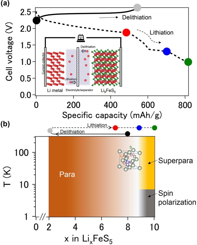
(a) Delithiation (solid) and lithiation (dashed) profiles for the Li8FeS5/C electrode at 298 K. The lithiation plateaus at approximately 2.0 V and 1.4 V correspond to the reduction of sulfur and Fe–S components, respectively. Inset: Schematic illustration of the Li8FeS5/Li cell. Li, Fe and S atoms are represented as red, blue and green spheres, respectively. (b) Schematic phase diagram of the Li–Fe–S system. The color symbols correspond to those in (a).
We therefore select the system as an underexplored but intriguing target, and report the magnetic and electronic properties of the products after Li ion propagation out of (delithiation) and into (lithiation) the pristine material by bulk magnetization, scanning spreading resistance microscopy (SSRM), ultraviolet photoemission spectroscopy (UPS) and magnetic force microscopy (MFM) measurements. We prepared, in a first step, several materials by fixing x in LixFeS5 using an electrochemical technique and investigated their magnetic properties to obtain an overview of the phase diagram. Perturbations by Li ions that have no net magnetization of their own transformed the pristine phase into a Pauli paramagnetic (PM) phase and a superparamagnetic (SPM) phase (Fig. 1b). In a second step, the two end members (x = 2 and 10) were studied in detail to understand their electronic properties, electronic states and local structures. As a result, the LixFeS5 system was found to exhibit electronic phase switching between a low-x conductive state and a high-x insulating state. Counter to our common belief, density functional theory (DFT) calculations suggest the monovalent Fe ion for x = 9.1 plays key roles in spin polarization.
Results and Discussion
Magnetic properties
The magnetization data were collected at five stages in the voltage profile (Fig. 1a). The χ(T) curve of pristine Li8FeS5 followed the Curie – Weiss law and yielded an effective magnetic moment (μeff) of 3.7 μB, where μB is the Bohr magneton. Both XRD analyses and high-energy X-ray total scattering measurements indicated that the pristine material was Fe-substituted (Li, Fe)2S9. The estimated μeff was consistent with μeff = 3.9 μB of Li8FeS5 (=(Li0.8Fe0.1)2S) with Li off-stoichiometry, in which the Fe2+ ions in the FeS4 tetrahedra are in a mixed state between an intermediate-spin state and a high-spin state.
Upon delithiation process, the Li ions were extracted from the Li8FeS5 host lattice (inset of Fig. 1a). The χ(T) curve for Li2FeS5 showed a Pauli-like lack of temperature dependence down to 100 K. The density of states at the Fermi level, N(EF), was estimated as 6.8 × 10²³ eV−1 cm−3 using the relation χ0 = μB2N(EF), where χ0 is the temperature independent χ. On the contrary, the χ for x ≥ 9 in LixFeS5 increased during lithiation (Fig. 2a) and there was a branch between the zero-field cooling (ZFC) and field cooling (FC) data at low temperature (Tirr). A cusp at a lower temperature in the ZFC curve appeared after the second plateau at approximately 1.4 V during the lithiation process (Fig. 1a). The peak temperature (Tp) for Li10FeS5 was 10 K at 100 Oe and shifted to lower temperatures with increasing magnetic field, maintaining the relationship Tp < Tirr. Such field variation of Tp is described by the power law, Tp ∝ [1 − (H/H0)]210 characteristic of superparamagnetism rather than antiferromagnetism (inset of Fig. 2a). Here, superparamagnetism appears in ferromagnetic (FM) or ferrimagnetic nanoscale particles. Magnetization analyses above 250 K where the Curie-like contribution with a Curie temperature of 90 K is dominant indicate the formation of magnetic polarons with an unusually high spin quantum number (S = 16), assuming that the g factor is 2 (Fig. S1). The concave, rather than convex, shape of the χ(T) curve also supports this scenario11.
Figure 2.
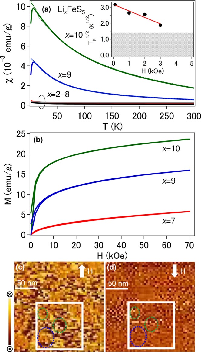
(a) Temperature dependence of magnetic susceptibility measured in the ZFC mode (solid) and the FC mode (dotted) in a field of 1 kOe. The color corresponds to that in Fig. 1a. Inset: Magnetic field dependence of Tp for x = 10. The solid line is the result of fitting Tp ∝ [1 – (H/H0)]210 to the data. Above 4 kOe, Tp was not observed down to 2 K. The temperature range below 2 K is described by gray. (b) Plot of 2 K magnetization versus magnetic field. (c,d) Two 200 nm × 200 nm MFM images taken of the same area at 150 K (>Tp) after lithiation (x = 10). A magnetic field of 5 kOe is applied (c) along the arrow and (d) in the reversed direction. Scale bar: 50 nm; MFM z-range: 3.6°. The frizzy or fuzzy appearance induced by the scanning process is visible, but we cannot exclude that part. The squares show the MFM images over a 100 nm × 100 nm area.
The magnetization at 2 K after the second plateau approached saturation at higher magnetic fields did not completely saturate even at 70 kOe (Fig. 2b). A magnetic hysteresis with a residual magnetization was observed and disappeared at 150 K (Fig. S2). As the particle size decreases to the nanoscale, the FM domain wall can no longer be defined. Thus, once an external field is removed above Tp, the thermal fluctuation cancels the residual magnetization. Based on the χ(T) and M(H) curves, Tp was assigned as the blocking temperature characteristic of SPM behavior, where the thermal energy becomes comparable with the energy required for spins to freeze. Here, binding and conductive additives are extrinsic since they are nonmagnetic.
MFM measurements
We obtained the FM spin polarization signal in the nanoparticles (NPs) after lithiation from the bulk magnetization measurements, but there was no evidence that the magnetic signal was intrinsic as this macroscopic technique once in a while captures signals originating from trivial sources. MFM is probably the most suitable method for investigating the SPM state as with the presence of NPs though we have used muons and neutrons to detect short/long-range FM order12,13. Dark and bright contrasts associated with the positive and negative phase shifts, respectively, were observed together with a high population of NPs (Fig. 2c,d). This indicates that the in-plane dipole moments arose from the NPs in the in-plane magnetic field. When the direction of the magnetic field is reversed, the contrast in the same region is reversed for the ideally isolated SPM NPs due to the flexible rotation of spins. In fact, the dark contrast turned the bright one with a magnetic field reversal and vice versa (green circles in Fig. 2c,d). The reason why the partial rotation is observed elsewhere is unclear, but the magnetic polarons quench the flexible rotation of spins. In particular, when one localized impurity spin and the carrier spins around the impurity form the magnetic polaron, the antiferromagnetic interaction between the localized impurities and the FM interaction between the magnetic polarons result in the small phase-shift change of the dark region, while remaining as the bright contrast (blue circles in Fig. 2c,d). There was also an area where the MFM image did not show a phase shift corresponding to the nonmagnetic acetylene black and binder. Since MFM measurements monitor a superposition of the magnetic and electrostatic signals, the displayed MFM data call into question the magnetic mechanism to some extent, but provide a plausible explanation reflecting most of the features of the FM spin-polarized NPs.
Resistance measurements
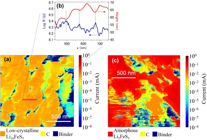
After lithiation, the local electronic resistance was position-dependent and its span varied by six orders of magnitude even in the area with no height corrugations (Fig. 3a color bar). There were some regions with high (blue), medium (yellow) and low (orange) resistance originating from the binder, acetylene black and the active material (Li10FeS5), respectively. The light-blue region may also correspond to a phase produced by the decomposition of electrolyte solution. The local resistance of the active material was generally in the range of semiconductors, which rules out the possibility of metallic Fe being included. The height profiles showed a periodic array of NPs 5–10 nm in height (Fig. 3b). The electronic resistance exhibited a cusp at these interfaces (Fig. 3b). These results are consistent with the properties of NPs. Attempts to measure the Hall effect for the compressed pellet have failed because of a high resistivity.
Figure 3.
SSRM images of the samples after (a) lithiation and (c) delithiation. (b) Height and resistance profiles along the marked path. Scale bar: 500 nm.
In contrast, after delithiation, also shown in Fig. 3c are some regions with high (blue), medium (yellow) and low (red) resistance, which correspond to the binder, acetylene black and the active material (Li2FeS5), respectively. The region with lower resistances corresponded well with the distribution of Fe and S atoms (Fig. S3). The resistance of the active material after delithiation was almost one-fiftieth of that after lithiation. Most interestingly, the electrons were predominately delocalized.
UPS measurements
Next, we performed UPS to investigate the electronic states around the EF (Fig. 4). No states near the EF were observed for the lithiated sample (Li10FeS5); in contrast, finite states at the EF were visible for the delithiated sample (Li2FeS5). The drastic change in the electronic states suggests switching between the insulating state and the conductive state by Li ions.
Figure 4.
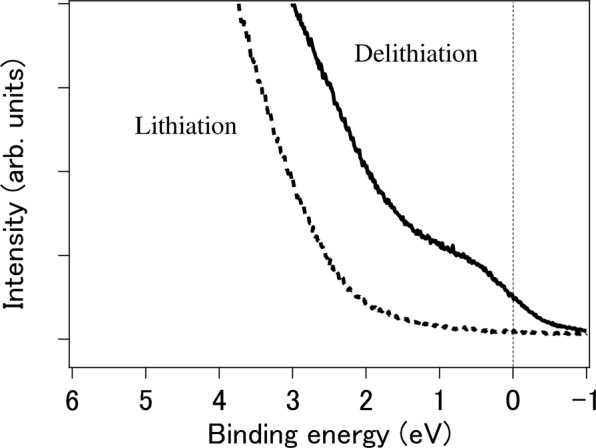
UPS spectra of the samples after delithiation (solid, x = 2) and lithiation (dashed, x = 10) at room temperature. The vertical line shows the Fermi level.
Local structural models
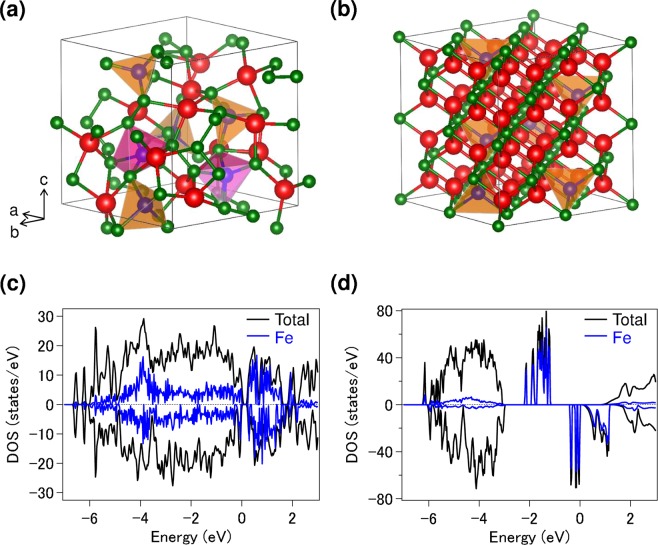
Finally, the local structural models that we consider by DFT calculations are shown in Fig. 5a,b. Pristine Li8FeS5 crystallizes in the Fmm space group, in which the Fe ions partially occupy the Li sites in Li2S9. LiS4 and FeS4 tetrahedra are included in the lattice and they are edge-shared. Delithiation (lithiation) induces the following two unique local structural changes: (i) formation of FeS5 trigonal bipyramids (FeS4 tetrahedra) and (ii) formation (dissociation) of S–S bonds. When Li is extracted from the pristine material, partial Li–S bond breaking is facilitated and the discrete S–S bonds are formed. In addition, FeS5 trigonal bipyramids and FeS4 tetrahedra coexist in the lattice. Since Fe ions are generally coordinated either teterahedrally or ocahedrally, the local coordination geometry in Li2.2Fe0.94S5 is counterintuitive. The existence of FeS5 trigonal bipyramids is hard to envisage experimentally. Specially, to the best of our knowledge, this coordination in inorganic compounds is the rare example. The displacement of the central Fe in FeS4 tetrahedra is a key to explain the formation of FeS5 trigonal bipyramids because the 4S tetra-framework remains. In overall, the lack of long-range periodicity (amorphous structure) in the predicted structure (Fig. 5a) is consistent with the previous experimental report8. On the contrary, for Li9.1Fe0.94S5, each element is arranged more periodically than in Li2.2Fe0.94S5. As shown in Fig. 5b, the framework of Li2S is predicted to be stable in the lattice, although Li is partially replaced by Fe, resulting in the formation of FeS4 tetrahedra and the dissociation of isolated S–S bonds.
Figure 5.
Models of local structures for (a) Li2.2Fe0.94S5 and (b) Li9.1Fe0.94S5. Fe–S clusters are shown by FeS5 trigonal bipyramids (purple) and FeS4 tetrahedra (brown). Lithium, iron and sulfur atoms are represented by red, blue and green spheres, respectively. Calculated density of states (DOS) for (c) Li2.2Fe0.94S5 and (d) Li9.1Fe0.94S5. Positive and negative values of DOS correspond to spin-up and -down, respectively.
DFT calculations also predict that the spin-up and -down Fe states are almost symmetrical for Li2.2Fe0.94S5, indicating a non-magnetic nature (Fig. 5c). However, for Li9.1Fe0.94S5, there is a band gap and the overall DOS feature becomes partially asymmetrical (Fig. 5d). Such imbalance in the up and down spins gives rise to ferromagnetism. The valence band near the EF is dominated by the Fe component. Spin polarization analyses suggest that the Fe+ ions are in the high-spin state (S = 3/2), which would be the origin of FM behavior. In addition, Bader charge analyses show that the average valences of Li, Fe and S ions are 0.77, 0.51 and −1.5, respectively. These results are reasonable each other. Although the prediction of the low valence state of Fe ions looks surprising, a low-valence state has also been predicted for LixTiS4 (e.g., Ti0.269+; x = 4)14.
Conclusion
In conclusion, Li ions drive a drastic phase transformation in the LixFeS5 system. Delithiation and lithiation accompanied by up to eight Li ions transform pristine Li8FeS5 into a Pauli paramagnetic conductor (amorphous Li2FeS5) and a superparamagnetic insulator (low-crystalline Li10FeS5), respectively. The findings boost our still-limited understanding of the ionic perturbations of magnetism and conduction. By carefully selecting fragile/reconfigure materials, the ionic perturbations extend far beyond other ones to realize new phases and emergent properties.
Methods
The primary electrochemical studies that carried out on Li8FeS5 have been reported elsewhere8. The bulk magnetization measurements were performed as described previously to avoid air exposure15. The local electronic resistance was measured by SSRM (AFM5000II, Hitachi High-Tech Science). The technique enables simultaneous local topographic and electronic resistance mapping on the surface of samples in real space. To confirm the repeatability, element distribution and absence of magnetic impurities, element mapping combined with SSRM (Park NX10, Park Systems) was performed using an Auger electron spectrometer (JAMP-9510F, JEOL) at room temperature. To investigate the electronic states near the EF in detail, HeI (21.22 eV) UPS measurements were performed at room temperature (PHI5000 VersaProbe I, ULVAC-PHI). To detect probe – sample interactions and analyze the magnetic properties of the NPs after lithiation, we conducted MFM measurements (AFM5300E, Hitachi High-Tech Science) under vacuum conditions (6.6 × 10⁻⁶ torr) at 150 K. First-principles calculations were performed using the projector augmented-wave (PAW) method16,17. The exchange-correlation functional was used within the generalized gradient approximation (GGA-PBE)18. The selected energy cutoff was 340 eV, and Brillouin zone integration was performed on a 2 × 2 × 2 k-point mesh. The structural parameters were fully optimized until the atomic Hellmann-Feynman forces were less than 0.05 eV Å−1 and all stress components were less than 0.01 eV Å−3. To model the Li2.2Fe0.94S5 (Li9.1Fe0.94S5) material, a 2 × 2 × 2 supercell containing 52 (96) atoms was applied. The structure models were visualized using the VESTA program19.
Supplementary information
Acknowledgements
This work was supported by the New Energy and Industrial Technology Development Organization (NEDO) of Japan under the Research and Development Initiative for Scientific Innovation of New Generation Batteries 2 (RISING2) project. The work related to the magnetization and MFM measurements was supported by the Nanotechnology Platform Program of the Ministry of Education, Culture, Sports, Science and Technology (MEXT), Japan. We thank N. Taguchi and H. Sakaebe of AIST for their contributions in the SSRM experiments. We are grateful to J.-S. Zhou and J. Sugiyama for discussion, A. Kitajima for his contributions in the MFM measurements and M. Usami for his contributions in the DFT calculations.
Author contributions
T.T. conceived and designed the research. T.T. measured the chemical/physical properties and wrote the manuscript. T. Take characterized the materials and performed the electrochemical tests. T.F. managed the project. All authors discussed the results.
Competing interests
The authors declare no competing interests.
Footnotes
Publisher’s note Springer Nature remains neutral with regard to jurisdictional claims in published maps and institutional affiliations.
Supplementary information
is available for this paper at 10.1038/s41598-019-56244-x.
References
- 1.Volbeda A, et al. Crystal structure of the nickel-iron hydrogenase from Desulfovibrio gigas. Nature. 1995;373:580–587. doi: 10.1038/373580a0. [DOI] [PubMed] [Google Scholar]
- 2.Peters JW, Lanzilotta WN, Lemon BJ, Seefeldt LC. X-ray crystal structure of the Fe-only hydrogenase (CpI) from clostridium pasteurianum to 1.8 angstrom resolution. Science. 1998;282:1853–1858. doi: 10.1126/science.282.5395.1853. [DOI] [PubMed] [Google Scholar]
- 3.Shima S, Lyon EJ, Thauer RK, Mienert B, Bill E. Mössbauer studies of the ironsulfur cluster-free hydrogenase: the electronic state of the mononuclear Fe active site. J. Am. Chem. Soc. 2005;127:10430–10435. doi: 10.1021/ja051895o. [DOI] [PubMed] [Google Scholar]
- 4.Berry JF, et al. An octahedral coordination complex of iron(VI) Science. 2006;312:1937–1941. doi: 10.1126/science.1128506. [DOI] [PubMed] [Google Scholar]
- 5.Kawasaki S, Takano M, Takeda Y. Ferromagnetic properties of SrFe1−xCoxO3 synthesized under high pressure. J. Solid State Chem. 1996;121:174–180. doi: 10.1006/jssc.1996.0025. [DOI] [Google Scholar]
- 6.Takano M, et al. Charge disproportionation in CaFeO3 studied with the Mössbauer effect. Mater. Res. Bull. 1977;12:923–928. doi: 10.1016/0025-5408(77)90104-0. [DOI] [Google Scholar]
- 7.Long YW, et al. intersite charge transfer in an A-site-ordered LaCu3Fe4O12 perovskite. Nature. 2009;458:60–63. doi: 10.1038/nature07816. [DOI] [PubMed] [Google Scholar]
- 8.Takeuchi T, et al. Preparation of Li2S–FeSx composite positive electrode materials and their electrochemical properties with pre-cycling treatments. J. Electrochem. Soc. 2015;162:A1745–A1750. doi: 10.1149/2.0301509jes. [DOI] [Google Scholar]
- 9.Takeuchi T, et al. Structure analyses of Fe-substituted Li2S-based positive electrode materials for Li–S batteries. Solid State Ionics. 2018;320:387–391. doi: 10.1016/j.ssi.2018.03.028. [DOI] [Google Scholar]
- 10.Bitoh T, Ohba K, Takamatsu M, Shirane T, Chikazawa S. Field-cooled and zero-field-cooled magnetization of superparamagnetic fine particles in Cu97Co3 alloy: comparison with spin-glass Au96Fe4 alloy. J. Phys. Soc. Jpn. 1995;64:1305–1310. doi: 10.1143/JPSJ.64.1305. [DOI] [Google Scholar]
- 11.Kaminski A, Sarma SD. Polaron percolation in diluted magnetic semiconductors. Phys. Rev. Lett. 2002;88:247202. doi: 10.1103/PhysRevLett.88.247202. [DOI] [PubMed] [Google Scholar]
- 12.Sugiyama J, et al. Evidence of two dimensionality in quasi-one-dimensional cobalt oxides. Phys. Rev. Lett. 2006;96:197206. doi: 10.1103/PhysRevLett.96.197206. [DOI] [PubMed] [Google Scholar]
- 13.Nozaki H, et al. Neutron diffraction and mSR study on the antiferromagnet BaCoO3. Phys. Rev. B. 2007;76:014402. doi: 10.1103/PhysRevB.76.014402. [DOI] [Google Scholar]
- 14.Sakuda A, et al. Amorphous metal polysulfides: electrode materials with unique insertion/extraction reactions. J. Am. Chem. Soc. 2017;139:8796–8799. doi: 10.1021/jacs.7b03909. [DOI] [PubMed] [Google Scholar]
- 15.Takami T, et al. Magnetic behavior of Fe nanoparticles driven by phase transition of FeF3. J. Alloys Compd. 2018;769:539–544. doi: 10.1016/j.jallcom.2018.08.040. [DOI] [Google Scholar]
- 16.Blochl PE. Projector augmented-wave method. Phys. Rev. B. 1994;50:17953–17979. doi: 10.1103/PhysRevB.50.17953. [DOI] [PubMed] [Google Scholar]
- 17.Kresse G, Joubert D. From ultrasoft pseudopotentials to the projector augmented-wave method. Phys. Rev. B. 1999;59:1758–1775. doi: 10.1103/PhysRevB.59.1758. [DOI] [Google Scholar]
- 18.Perdew JP, Burke K, Ernzerhof M. Generalized gradient approximation made simple. Phys. Rev. Lett. 1996;77:3865–3868. doi: 10.1103/PhysRevLett.77.3865. [DOI] [PubMed] [Google Scholar]
- 19.Momma K, Izumi F. VESTA: a three-dimensional visualization system for electronic and structural analysis. J. Appl. Crystallogr. 2008;41:653–658. doi: 10.1107/S0021889808012016. [DOI] [Google Scholar]
Associated Data
This section collects any data citations, data availability statements, or supplementary materials included in this article.


