Abstract
Purpose
This study was performed to investigate the effects of energy level, reconstruction kernel, and tube rotation time on Hounsfield unit (HU) values of hydroxyapatite (HA) in virtual monochromatic images (VMIs) obtained with dual-energy computed tomography (DECT) (Siemens Healthineers, Erlangen, Germany).
Materials and Methods
A bone density calibration phantom with 3 HA inserts of different densities (CTWATER®; 0, 100, and 200 mg of HA/cm3) was scanned using a twin-beam DECT scanner at 120 kVp with tube rotation times of 0.5 and 1.0 seconds. The VMIs were reconstructed by changing the energy level (with options of 40 keV, 70 keV, and 140 keV). In order to investigate the impact of the reconstruction kernel, virtual monochromatic images were reconstructed after changing the kernel from body regular 40 (Br40) to head regular 40 (Hr40) in the reconstruction phase. The mean HU value was measured by placing a circular region of interests (ROIs) in the middle of each insert obtained from the VMIs. The HU values were compared with regard to energy level, reconstruction kernel, and tube rotation time.
Results
Hydroxyapatite density was strongly correlated with HU values (correlation coefficient=0.678, P<0.05). For the HA 100 and 200 inserts, HU decreased significantly at increased energy levels (correlation coefficient= −0.538, P<0.05) but increased by 70 HU when using Hr40 rather than Br40 (correlation coefficient=0.158, P<0.05). The tube rotation time did not significantly affect the HU (P>0.05).
Conclusion
The HU values of hydroxyapatite were strongly correlated with hydroxyapatite density and energy level in VMIs obtained with DECT.
Keywords: Computed Tomography, Hydroxyapatite, Image Reconstruction
Introduction
Dual-energy computed tomography (DECT) uses different X-ray spectra to enhance material differentiation and tissue characterization.1 The main technical approaches for DECT are dual-source CT (DSCT) and fast kVp-switching CT.2 DSCT obtains low- and high-energy data using 2 separate data acquisition systems (i.e. tube and detector) and performs material decomposition in the image space. Fast kVp-switching CT acquires high- and low-energy data sets using rapid tube voltage switching between 80 and 140 kVp and performs material decomposition in the projection space.3 Another method, dual-layer spectral CT (DLSCT), acquires energy-sensitive data through a dual-layer detector. The upper detector accepts lower-energy photons, and the lower layer simultaneously accepts higher-energy photons.4 Split-filter DECT uses a gold/tin filter to split the beam into 2 different energy spectra. Filtration using gold results in a low-energy spectrum, while filtration using tin yields a high-energy spectrum. The spectral separation makes reconstruction of low-energy (Au 120 kV) or high-energy (Sn 120 kV) images possible, for which only the corresponding half of the detector is used.5
Because it uses 2 different X-ray energy spectra, DECT has several applications, including mono-energetic extrapolation. Reconstruction of virtual monochromatic images (VMIs) at several different energy levels is possible using a post-processing algorithm and reveals various image parameters from a single CT exposure, such as attenuation and noise.6 DECT can be used to perform material decomposition to determine the concentration of iodine present in blood vessels or tissues, which improves diagnostic accuracy.7
CT numbers, or Hounsfield units (HU), can provide information about the X-ray attenuation characteristics of parts of a patient's body relative to water. HU values are used for tissue characterization during diagnosis and obtained values can be compared with normal HU values reported in the radiological literature.8
However, HU values are also affected by the energy spectrum and X-ray beam filtration, as well as manufacturer specifications, reconstruction artifacts, beam hardening, scanner linearity, object orientation and size, the scanning method used, and the geometric features of the patient.9,10,11
With DECT, the difference between the theoretical attenuation coefficient and the measured attenuation coefficient in soft tissue at various iodine concentrations has been found to vary according to energy level.12 Additionally, with DLSCT, the HU values of iodine in VMIs were found to be affected by the radiation dose.3
Hydroxyapatite (HA) is a naturally-occurring mineral form of calcium apatite with the formula Ca10(PO4)6(OH)2. Material containing up to 50% by volume and 70% by weight of human bone is considered a modified form of HA, known as bone mineral.13 HA has been used to investigate the accuracy of bone mineral density quantification using DLSCT for the evaluation of osteoporosis.14
The reconstruction kernel, also referred to as the filter or algorithm by some CT vendors, is one of the most critical parameters affecting image quality. A smooth kernel generates images with relatively low noise, but relatively low spatial resolution. A sharp kernel generates images with higher spatial resolution, but increased image noise. Selection of the reconstruction kernel should be based on specific clinical applications. Smooth kernels are usually used in brain exams or liver tumor assessments to reduce image noise and enhance low-contrast detectability, whereas sharper kernels are typically used to assess bony structures because of the clinical requirement for greater spatial resolution.15 In contrast-enhanced DSCT coronary angiography, HU values have been found to change according to the reconstruction kernel used.16
The purpose of this study was to investigate the effects of energy level, reconstruction kernel, and tube rotation time on the HU values of hydroxyapatite in VMIs obtained with DECT.
Materials and Methods
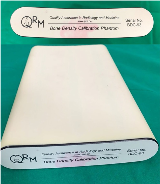
A bone density calibration phantom (QRM, Moehrendorf, Germany) was used for this study. This phantom contained 3 HA inserts of different densities, specifically 0, 100, and 200 mg of HA/cm3. As a base material for the 3 inserts, CTWATER® (QRM, Moehrendorf, Germany) was used. CTWATER® is a solid water-equivalent plastic that offers the same X-ray attenuation properties as water. In this study, CTWATER® represented an insert of 0 mg of HA/cm3, which was used instead of water. HA 100 and HA 200 represented HA inserts with densities of 100 mg and 200 mg of HA/cm3, respectively (Fig. 1).
Fig. 1. A bone density calibration phantom (QRM, Moehrendorf, Germany) contained 3 inserts of different densities (0, 100, and 200 mg of hydroxyapatite [HA]/cm3). As a base material for the 3 inserts, CTWATER® (QRM, Moehrendorf, Germany) was used. CTWATER® is a solid water-equivalent plastic offering the same X-ray attenuation properties as water. In this study, CTWATER® represents 0 mg of HA/cm3. HA 100 and HA 200 represent 100 mg and 200 mg, respectively, of HA/cm3.
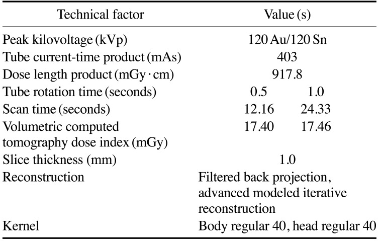
DECT images of the phantom were obtained with a SOMATOM Definition EDGE (Siemens Healthineers, Erlangen, Germany) device, a third-generation twin-beam scanner. The technical factors involved in DECT use are described in Table 1.
Table 1. Technical factors for twin-beam dual-energy computed tomography used in this study.
Image acquisition of the phantom was taken at 120 Au/120 Sn kVp in DECT twin-beam mode, with tube rotation times of 0.5 and 1.0 seconds, a tube current-time product of 403 mA, and a slice thickness of 1.0 mm. The scan times were 12.16 and 24.33 seconds at 0.5 and 1.0 seconds of tube rotation time, respectively. The volumetric CT dose (CTDIvol) indexes were 17.40 and 17.46 mGy at 0.5 and 1.0 seconds of tube rotation time, respectively. Each individual image was reconstructed using the body regular 40 (Br40) reconstruction kernel (a smooth kernel commonly used for body reconstruction) and the head regular 40 (Hr40) reconstruction kernel (a sharp kernel commonly used for head reconstruction). The number specifies the sharpness. Reconstructed data were imported into special software (SYNGO.via, Siemens Healthineers, Erlangen, Germany) to obtain the VMIs at 40 keV, 70 keV, and 140 keV.
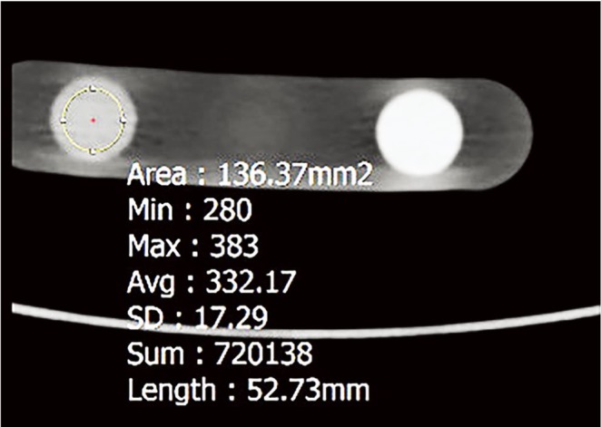
All measurements were carried out using a commercially available picture archiving and communication system workstation (Inifinitt Healthcare, Seoul, Korea) by 1 oral and maxillofacial radiology postgraduate student. On the phantom images, mean HU values were measured via placing a circular region of interests (ROIs) in the center of the CTWATER®, HA 100, and HA 200 inserts. The ROIs were kept at a constant area of approximately 136.0 mm2 using the copy-and-paste function of the workstation. To avoid a partial volume averaging effect, the ROIs were determined so as not to include the edge of the HA inserts. The window-level setting was set to a width of 1800 and a level of 500 (Fig. 2). For each image, the HU values of the inserts were measured repeatedly in 11 consecutive slices. The HU value of each insert was measured 33 times in total for each scan protocol.
Fig. 2. On the cross-sectional image of the phantom, the mean Hounsfield (HU) is measured via placing a circular region of interests (ROIs) in the center of the HA 100 insert. Min: minimum value, Max: maximum value, Avg: average value, SD: standard deviation.
Using the obtained HU data, the linear attenuation coefficient of HA was estimated at each energy level.
| [1] |
| [2] |
where ρHA refers to the HA density, is the HA mass attenuation coefficient at energy E, and (ρHA) is the linear attenuation coefficient of the HA.3,17
Mass attenuation coefficients were obtained from the National Insitute of Standard and Technology XCOM database.18
The Pearson correlation coefficient was determined to estimate the correlations between HA density, energy level, reconstruction kernel, and the rotation time and the HU of the VMIs. Commercially available software (SPSS version 21.0 for Windows; IBM Corp., Armonk, NY, USA) was used for statistical analyses. A P-value<0.05 was considered to indicate statistical significance.
Results
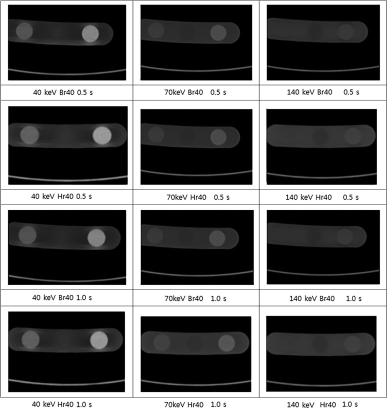
The VMIs of HA inserts of various densities obtained by DECT displayed differences in image contrast and image noise depending on energy level, reconstruction kernel, and rotation time (Fig. 3).
Fig. 3. Virtual monochromatic images of hydroxyapatite inserts of various densities obtained with dual-energy computed tomography show the differences in the image contrast and image noise depending on energy level, reconstruction kernel, and rotation time (seconds).
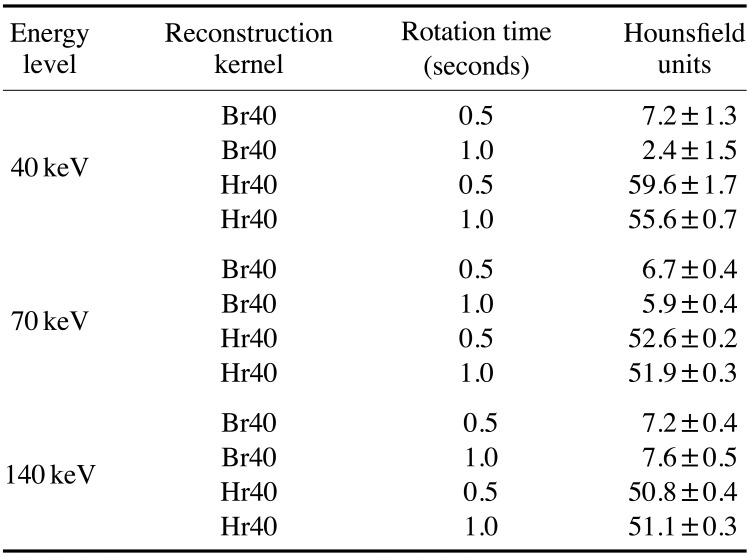
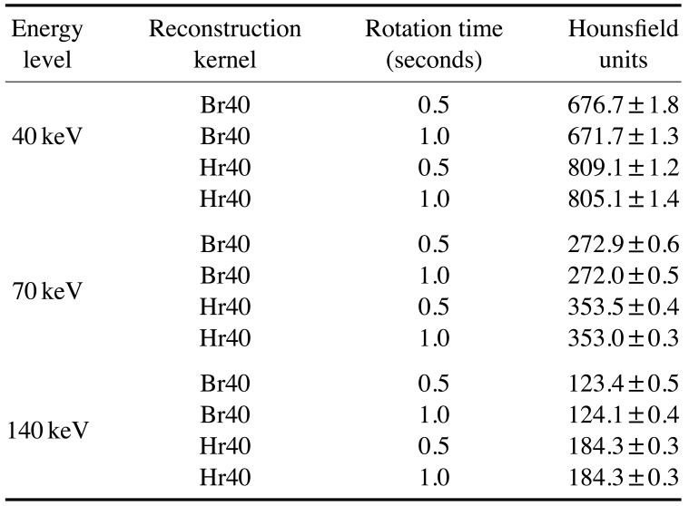
Virtually no difference in HU values were observed according to the energy level or rotation time used with the CTWATER® insert. However, the HU value was 40–50 HU higher when Hr40 was used than when Br40 was used (Table 2), with a weak correlation (correlation coefficient=0.158, P<0.05, Table 5).
Table 2. Mean Hounsfield unit values for 0 mg of hydroxyapatite/cm3 (CTWATER®) according to energy level, reconstruction kernel, and rotation time.
Table 5. Pearson correlation coefficients of variables affecting Hounsfield units.
*P<0.05
As the energy level increased with the HA 100 insert, the HU values markedly decreased (Table 3). Furthermore, values of 50-100 HU higher were found when using the Hr40 than when using the Br40 kernel (Table 3). However, the change in HU values due to the reconstruction kernel used was not large compared to that due to HA density or energy level (correlation coefficient=0.158, P<0.05, Table 5). Rotation time did not significantly affect HU values (correlation coefficient= −0.003, P>0.05, Table 5).
Table 3. Mean Hounsfield unit values for 100 mg of hydroxyapatite/cm3 (HA 100) according to energy level, reconstruction kernel, and rotation time.
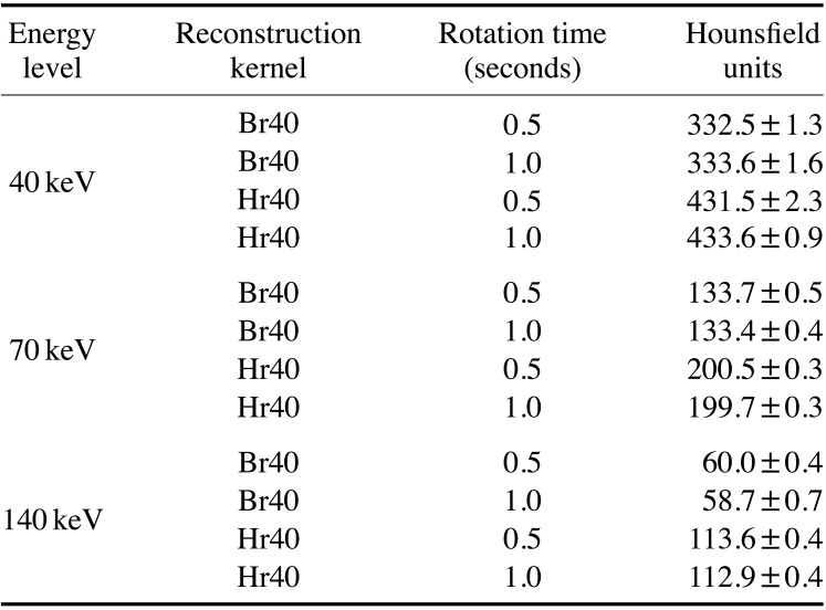
Similar to the 100 HA insert, with the 200 HA insert, as the energy level increased, the HU values decreased (Table 4). The value was 60-130 HU higher when using Hr40 than when using Br40 (Table 4), showing a weak correlation (correlation coefficient=0.158, P<0.05). Rotation time did not significantly affect HU values (correlation coefficient= −0.003, P>0.05, Table 5).
Table 4. Mean Hounsfield unit values for 200 mg of hydroxyapatite/cm3 (HA 200) according to energy level, reconstruction kernel, and rotation time.
HU values were strongly correlated with HA density, and the correlation coefficient for this relationship was 0.678 (P<0.05). In contrast, HU and energy levels were negatively correlated (correlation coefficient= −0.538, P<0.05, Table 5).
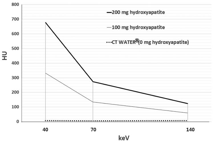
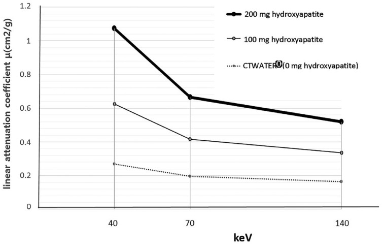
Additionally, HU values increased with HA density, but decreased with increasing energy levels (Fig. 4). Virtually no difference was found in the linear attenuation coefficient according to energy level with CTWATER®. The linear attenuation coefficient increased with HA density, but decreased with increasing energy levels (Fig. 5).
Fig. 4. Hounsfield units (HU) for CTWATER® (0 mg), 100, and 200 mg of hydroxyapatite/cm3 according to energy level (40, 70, or 140 keV) with a body regular 40 kernel and a 0.5 second tube rotation time. Virtually no difference in HU is observed according to the energy level of CTWATER®. The HU value increases with hydroxyapatite density, but decreases markedly with increasing energy levels.
Fig. 5. Linear attenuation coefficient µ (cm2/g) of CTWATER® (0), 100, and 200 mg of hydroxyapatite/cm3 according to energy level (40, 70, or 140 keV). Virtually no difference is observed in the linear attenuation coefficient according to the energy level of CTWATER®. The linear attenuation coefficient increases with hydroxyapatite density but decreases with increasing energy level.
Discussion
HU values are inherently based on substance concentration and are often used to perform density comparisons for diagnostic purposes. Okayama et al.19 reported that the influence of effective energy on HU in monoenergetic cardiac imaging varies depending on the material and tissue type. In their study, graphs of the linear attenuation coefficient, or µ(E), and the energy (in kiloelectron volts, keV), which are factors related to HU, were shown for iodine mass densities of 0.1 g/cm3 and 1.0 g/cm3. Their results showed that the µ(E) of both materials decreased as the energy level increased. Overall, the µ(E) value was higher at an iodine density of 1.0 g/cm3.20 In our experiment, the linear attenuation coefficient of HA decreased as the energy level increased (Fig. 5). HA is composed of various elements, with a chemical formula of Ca10(PO4)6(OH)2 however, the HU values of HA change according to the energy level and density, as shown in previous studies of iodine. Therefore, radiologists should consider this correlation when comparing the HU values of HA for VMIs reconstructed with DECT.
Fornaro et al.21 presented the linear attenuation coefficient according to the energy level in bone, iodine, and water. They estimated the linear attenuation coefficient of bone but did not report the difference in density. The linear attenuation coefficient of CTWATER® in our study was similar to that of the previous study. Additionally, in this study, a linear attenuation coefficient curve similar to that of bone was obtained using the HA 200 insert. The HA 100 insert showed a decrease in slope of the linear coefficient curve from −0.0045 to −0.0007 as the energy level increased. With the HA 200 insert, the slope decreased from −0.0067 to −0.0009 as the energy level increased. Since the slope changes according to the energy level, HA density at a certain energy level can be measured if the slope is obtained at that same level.
When observing atherosclerotic plaques on a DSCT system according to the sharpness of the reconstruction kernel value, the medium soft kernel for cardiac applications (B26f) yielded 113 HU, while the sharp kernel (B46f) yielded 79 HU.16 Birnbaum et al. reported that CT attenuation values obtained with multislice computed tomography may vary depending on the combination of the scanner and the reconstruction kernel.22 The Br40 kernel that was used in this study is a smooth kernel and is mainly utilized in brain and body observations to reduce image noise and to increase contrast. The Hr40 kernel is a sharp kernel that is primarily used to improve spatial resolution and to observe bony structures. This study also showed a difference of about 70 HU depending on the type of reconstruction kernel (Br40 or Hr40) used, but this difference was not statistically significant (correlation coefficient= 0.158). However, when reconstructing an image to calculate bone density, it is recommended to compare values obtained with the same kernel to reduce errors.
Lu et al.3 showed that in VMIs, HU accuracy was significantly degraded when the CTDIvol was 10 mGy or lower. At a CTDIvol of 10 mGy or lower, VMI CT values tended to be affected by radiation dose. In our experiment, with rotation times of 0.5 seconds and 1.0 seconds, the CTDIvol was 17.40 mGy and 17.46 mGy, respectively. Neither of the HU correlation coefficients for these rotation times was statistically significant. However, when evaluating low-HU structures, such as fat or muscle, which are mainly observed in the head and neck, even small changes can produce significant results.
In conclusion, the HU values of HA are strongly correlated with HA density and energy level during DECT imaging. Based on this finding, we believe that DECT can accurately express bone density in HA units, but further research is needed.
Footnotes
This study was supported by grant no 04-2015-0082 from the SNUDH Research Fund.
Conflicts of Interest: None
References
- 1.Forghani R, De Man B, Gupta R. Dual-energy computed tomography: physical principles, approaches to scanning, usage, and implementation: part 1. Neuroimaging Clin N Am. 2017;27:371–384. doi: 10.1016/j.nic.2017.03.002. [DOI] [PubMed] [Google Scholar]
- 2.Johnson TR. Dual-energy CT: general principles. AJR Am J Roentgenol. 2012;199(5 Suppl):S3–S8. doi: 10.2214/AJR.12.9116. [DOI] [PubMed] [Google Scholar]
- 3.Lu X, Lu Z, Yin J, Gao Y, Chen X, Guo Q. Effects of radiation dose levels and spectral iterative reconstruction levels on the accuracy of iodine quantification and virtual monochromatic CT numbers in dual-layer spectral detector CT: an iodine phantom study. Quant Imaging Med Surg. 2019;9:188–200. doi: 10.21037/qims.2018.11.12. [DOI] [PMC free article] [PubMed] [Google Scholar]
- 4.Rassouli N, Etesami M, Dhanantwari A, Rajiah P. Detector-based spectral CT with a novel dual-layer technology: principles and applications. Insights Imaging. 2017;8:589–598. doi: 10.1007/s13244-017-0571-4. [DOI] [PMC free article] [PubMed] [Google Scholar]
- 5.Euler A, Parakh A, Falkowski AL, Manneck S, Dashti D, Krauss B, et al. Initial results of a single-source dual-energy computed tomography technique using a split-filter: assessment of image quality, radiation dose, and accuracy of dual-energy applications in an in vitro and in vivo study. Invest Radiol. 2016;51:491–498. doi: 10.1097/RLI.0000000000000257. [DOI] [PubMed] [Google Scholar]
- 6.Yu L, Leng S, McCollough CH. Dual-energy CT-based monochromatic imaging. AJR Am J Roentgenol. 2012;199(5 Suppl):S9–S15. doi: 10.2214/AJR.12.9121. [DOI] [PubMed] [Google Scholar]
- 7.Fulton N, Rajiah P. Abdominal applications of a novel detector-based spectral CT. Curr Probl Diagn Radiol. 2018;47:110–118. doi: 10.1067/j.cpradiol.2017.05.001. [DOI] [PubMed] [Google Scholar]
- 8.Hamrahian AH, Ioachimescu AG, Remer EM, Motta-Ramirez G, Bogabathina H, Levin HS, et al. Clinical utility of noncontrast computed tomography attenuation value (Hounsfield units) to differentiate adrenal adenomas / hyperplasias from nonadenomas: Cleveland Clinic experience. J Clin Endocrinol Metab. 2005;90:871–877. doi: 10.1210/jc.2004-1627. [DOI] [PubMed] [Google Scholar]
- 9.Levi C, Gray JE, McCullough EC, Hattery RR. The unreliability of CT numbers as absolute values. AJR Am J Roentgenol. 1982;139:443–447. doi: 10.2214/ajr.139.3.443. [DOI] [PubMed] [Google Scholar]
- 10.Lamba R, McGahan JP, Corwin MT, Li CS, Tran T, Seibert JA, et al. CT Hounsfield numbers of soft tissues on unenhanced abdominal CT scans: variability between two different manufacturers' MDCT scanners. AJR Am J Roentgenol. 2014;203:1013–1020. doi: 10.2214/AJR.12.10037. [DOI] [PMC free article] [PubMed] [Google Scholar]
- 11.Sande EP, Martinsen AC, Hole EO, Olerud HM. Interphantom and interscanner variations for Hounsfield units - establishment of reference values for HU in a commercial QA phantom. Phys Med Biol. 2010;55:5123–5135. doi: 10.1088/0031-9155/55/17/015. [DOI] [PubMed] [Google Scholar]
- 12.Jacobsen MC, Schellingerhout D, Wood CA, Tamm EP, Godoy MC, SUN J, et al. Intermanufacturer comparison of dual-energy CT iodine quantification and monochromatic attenuation: a phantom study. Radiology. 2018;287:224–234. doi: 10.1148/radiol.2017170896. [DOI] [PubMed] [Google Scholar]
- 13.Junqueira LC, Carneiro J. Basic histology: text & atlas. 10th ed. New York: McGraw-Hill Companies; 2003. p. 144. [Google Scholar]
- 14.van Hamersvelt RW, Schilham AM, Engelke K, den Harder AM, de Keizer B, Verhaar HJ, et al. Accuracy of bone mineral density quantification using dual-layer spectral detector CT: a phantom study. Eur Radiol. 2017;27:4351–4359. doi: 10.1007/s00330-017-4801-4. [DOI] [PMC free article] [PubMed] [Google Scholar]
- 15.Yu L, Leng S. Image reconsgruction techniques [Internet] Reston: American College of Radiology; 2016. [cited 2019 Sep 11]. Availaboe from: https://www.imagewisely.org/Imaging-Modalities/Computed-Tomography/Image-Reconstruction-Techniques. [Google Scholar]
- 16.Achenbach S, Boehmer K, Pflederer T, Ropers D, Seltmann M, Lell M, et al. Influence of slice thickness and reconstruction kernel on the computed tomographic attenuation of coronary atherosclerotic plaque. J Cardiovasc Comput Tomogr. 2010;4:110–115. doi: 10.1016/j.jcct.2010.01.013. [DOI] [PubMed] [Google Scholar]
- 17.NDT Education Resource Center [Internet] Ames: Iowa State University; 2001–2014. [cited 2019 Sep 11]. Transmitted intensity and linear attenuation coefficient. Available from: https://www.nde-ed.org/EducationResources/CommunityCollege/Radiography/Physics/attenuationCoef.htm. [Google Scholar]
- 18.Hubbell JH, Seltzer SM. NIST Standard Reference Database 126. Tables of X-ray mass attenuation coefficients and mass energy-absorption coefficients from 1 keV to 20 MeV for elements Z=1 to 92 and 48 additional substances of dosimetric interest [Internet] Gaithersburg: National Institute of Standards and Technology; 1996. [cited 2019 Sep 11]. Available from: https://www.nist.gov/pml/x-ray-mass-attenuation-coefficients. [Google Scholar]
- 19.Okayama S, Soeda T, Takami Y, Kawakami R, Somekawa S, Uemura S, et al. The Influence of effective energy on computed tomography number depends on tissue characteristics in monoenergetic cardiac imaging. Radiol Res Pract. 2012;2012:150980. doi: 10.1155/2012/150980. [DOI] [PMC free article] [PubMed] [Google Scholar]
- 20.McCollough CH, Leng S, Yu L, Fletcher JG. Dual- and multi-energy CT: principles, technical approaches, and clinical applications. Radiology. 2015;276:637–653. doi: 10.1148/radiol.2015142631. [DOI] [PMC free article] [PubMed] [Google Scholar]
- 21.Fornaro J, Leschka S, Hibbeln D, Butler A, Anderson N, Pache G, et al. Dual- and multi-energy CT: approach to functional imaging. Insights Imaging. 2011;2:149–159. doi: 10.1007/s13244-010-0057-0. [DOI] [PMC free article] [PubMed] [Google Scholar]
- 22.Birnbaum BA, Hindman N, Lee J, Babb JS. Multi-detector row CT attenuation measurements: assessment of intra- and interscanner variability with an anthropomorphic body CT phantom. Radiology. 2007;242:109–119. doi: 10.1148/radiol.2421052066. [DOI] [PubMed] [Google Scholar]


