Abstract
Regular monitoring of blood flow and pressure in vascular reconstructions or grafts would provide early warning of graft failure and improve salvage procedures. Based on biocompatible materials, we have developed a new type of thin, flexible pulsation sensor (FPS) which is wrapped around a graft to monitor blood pressure and flow. The FPS uses carbon black (CB) nanoparticles dispersed in polydimethylsiloxane (PDMS) as a piezoresistive sensor layer, which was encapsulated within structural PDMS layers and connected to stainless steel interconnect leads. Because the FPS is more flexible than natural arteries, veins, and synthetic vascular grafts, it can be wrapped around target conduits at the time of surgery and remain implanted for long-term monitoring. In this study, we analyze strain transduction from a blood vessel and characterize the electrical and mechanical response of CB-PDMS from 0–50% strain. An optimum concentration of 14% CB-PDMS was used to fabricate 300-μm thick FPS devices with elastic modulus under 500 kPa, strain range of over 50%, and gauge factor greater than 5. Sensors were tested in vitro on vascular grafts with flows of 0–1,100 mL/min. In vitro testing showed linear output to pulsatile flows and pressures. Cyclic testing demonstrated robust operation over hundreds of cardiac cycles, with ±2.6 mmHg variation in pressure readout. CB-PDMS composite material showed excellent potential in biologic strain sensing applications where a flexible sensor with large maximum strain range is needed.
Index Terms—: Carbon Black, Flexible Pulsation Sensor, PDMS, Strain Sensing, Vascular Graft
I. Introduction
Synthetic arteriovenous vascular grafts are widely used for bypass or for vascular access in hemodialysis, and over one million grafts are implanted annually in the US [1]. Maintaining the graft’s functional blood flow (patency) is critical to avoid thrombosis (occlusion) which can lead to loss of the graft. Vascular grafts most commonly fail due to intimal hyperplasia, in which the graft lumen diameter is reduced as endothelial cells migrate to the graft surface [1]. This reduces graft blood flow, changes pressure gradients, and increases the risk of blood clotting [2]. Early detection of changing blood flow or pressure in a graft can enable the use of medical imaging or early interventions to best salvage the graft before it is lost [3]. Current technologies, however, mostly rely on imaging and expert interpretation. They are therefore too costly for widespread and regular surveillance of all implanted grafts [4–6]. As a result, 20–38% of vascular grafts fail in the first year [7], resulting in hospitalizations and other major health complications. Real-time detection of 25% drop in blood flow [8]could identify patients for early intervention to prevent graft loss. This requires frequent measurements of graft function, ideally in the patient’s natural environment.
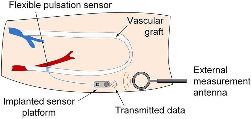
One approach to chronic, non-blood-contacting vascular monitoring is to use polymeric strain sensors wrapped around the blood vessel or graft. These flexible pulsation sensors (FPS) could be applied at the time of surgery and monitored using nearfield electronic transceivers (Fig. 1). Changes in blood flow would indicate endovascular leakage or a failing graft in near real time.
Fig. 1.
An implanted flexible pulsation sensor can be wrapped around a blood vessel or synthetic graft during surgery and coupled to a miniature electronic platform for on-demand monitoring of vascular pressure and flow.
Blood pressure and flow can also be measured with sensors placed in the lumen of the graft [9–10], but this approach could accelerate graft failure by altering the graft mechanical structure [1, 11]. Transcutaneous Doppler flow probes are wrapped on the outside of blood vessels; these devices are removed after several days and generally provide qualitative confirmation of vascular patency. More complex ultrasonic probes are in development to quantify blood flow volumes, and to potentially support implantable chronic use.
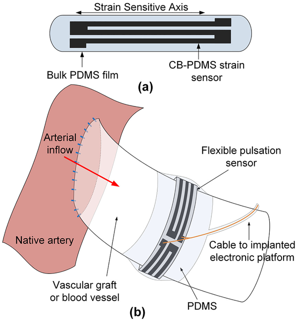
Prior examples of FPS devices have focused exclusively on monitoring synthetic grafts using polymer films such as polyvinyl-fluoride [12–14] or aluminum nitride [15] or sensors constrained to rigid metal rings [16]. These approaches relied on the low elasticity and fixed geometry of synthetic grafts [17], and required sensors to be adhered to the grafts before implantation. Here, we present the development of FPS devices with greatly enhanced flexibility, which enables operative placement during graft implantation or vascular repair (Fig. 2). The FPS device can be wrapped around natural blood vessels or synthetic grafts at the time of surgery and remain implanted without constriction if the material is more flexible than the host vessel or graft [18]. The silicone-based cuffs of temporary Doppler flow probes, for example, remain permanently wrapped around blood vessels even after the monitoring leads are removed [19]. Use of these invasive devices is justified by the surgical environment in which vascular repairs and graft implantations are performed.
Fig. 2.
The FPS is a piezoresistive CB-PDMS implantable strain sensor (a) which is wrapped around a vessel or graft and secured with a PDMS film. As the FPS moves with the vessel wall it transduces pulsatile blood flow (b).
To enable an FPS that could be used on natural blood vessels or synthetic grafts, we developed piezoresistive elastomer composites to be used as the FPS transduction material. Unlike metals or other piezoelectric polymers, these elastomeric strain sensors can measure >20% strain without damage [20]. Prior work established that polydimethylsiloxane (PDMS) doped with conductive particles or nanotubes demonstrated a robust piezoresistive strain response over large strain ranges [20–25].
Here, we expand upon previous work using carbon black (CB) nanoparticle polydimethylsiloxane (PDMS) composite PDMS (CB-PDMS) [25] as a strain sensitive bio-material for FPS applications. We present an analysis of pressure-flow transduction using a strain sensor wrapped around a blood vessel and select an optimum CB-PDMS composite from mechanical and electrical characterization. Finally, we present in vitro data showing that CB-PDMS based FPS devices can sense physiologic blood pressure and flow without blood contact in vascular grafts.
This paper is organized as follows: first, we present a simplified transduction analysis relating FPS strain to graft pressure and flow for natural arteries, veins, and synthetic grafts. Second, we present electrical and mechanical characterization of CB-PDMS composites. Third, we present fabrication details of FPS sensors. Finally, we demonstrate in vitro FPS test results on vascular grafts under physiologic pressures and flows.
II. Flexible Pulsation Sensor Pressure-Flow Transduction
Arteries and veins expand during the systolic cardiac phase, due to the incompressible properties of blood. In one representative study, 6-mm femoral arteries expanded by an average 0.12 mm during the systolic phase of normal pulsatile blood flow (2.0% diameter expansion). Similarly, large 13.7-mm femoral veins expanded by 0.19 mm on systole (1.4% diameter expansion) [26]. Although veins are more compliant than arteries, they are exposed to lower pressures and so have similar expansion during pulsatile flow [17, 27, 28].
Synthetic vascular grafts are engineered, in part, to approximate the elasticity of human vessels, but even widely used expanded polytetrafluoroethylene (ePTFE) grafts have elastic modulus greater than natural vessels [15, 26, 28]. As a result, pulsatile expansion of 6-mm diameter ePTFE grafts is significantly lower than arteries and veins.
A. FPS and Blood Vessel Pressure-Strain Relationship
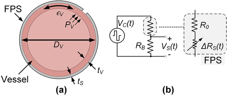
The FPS was designed to measure the small wall deflection occurring during pulsation in synthetic vascular grafts or in natural vessels. Here, we analyze a simplified transduction model relating vessel pressure and flow to FPS mechanical strain and voltage conversion (Fig. 3a). This model was based on several assumptions. First, the FPS was assumed to be more compliant than the vessel, such that the addition of the FPS did not change the strain of the vessel. This assumption holds because the FPS has a lower elastic modulus than the graft material (described in Section IIIC). Second, we assumed perfect mechanical coupling between the FPS and the vessel so they expand and contract together. This assumption holds in practice when the FPS is mechanically wrapped around the graft under slight tension so the two materials move as one (described in Section IV). Third, we assumed laminar blood flow and applied the Poiseuille equation to linearly relate vessel flow QV and pressure PV by a factor η, i.e. ηQV = PG [29]. This simplified model is widely used in vascular physiology. Finally, we assumed a cylindrical vessel undergoing isotropic expansion during pulsation. This assumption holds as long as the graft/vessel has no defects or thickness changes around the circumference.
Fig. 3.
A simple graft model (a) assumes that the FPS experiences the graft strain ∈G generated by pressure PV. The FPS in a half bridge circuit (b) is modeled as a fixed R0 in series with a strain-dependent RS.
For a cylindrical tube, circumferential stress σθ is approximated by Barlow’s equation and related to the vessel Young’s modulus by Ev by
| (1) |
where ∈v is the circumferential strain in the vessel, DV is the vessel diameter, and tv is the vessel thickness. The FPS thickness ts ≪ tv, implying that the vessel’s thickness is mechanically dominant and that the diameter of the FPS is approximately equal to DV.
During pulsation the change in circumferential length ΔL can be calculated through circumferential strain (∈G = ΔL/L0):
| (2) |
Under a pressure Pv, the FPS strain ∈s is approximately
| (3) |
which is the same as (1) with the assumption ∈s = ∈v. To first order, ∈s is therefore linearly proportional to both vessel pressure and flow.
For the FPS in a half bridge circuit with RB (Fig. 3b), R0 is the nominal FPS resistance and ΔRs(t) is the time-variant sensor resistance under periodic pulsatile pressure wave Pv(t). ΔRs(t) can be derived using a strain sensor gauge factor (GF) conversion
| (4) |
The change in sensor resistance is related to vessel flow through the Poiseuille equation, ηQv(t) =Pv(t). If RB is chosen as RB=R0, the flow-dependent sensor output is given by
| (5) |
where Vc(t) is the bridge excitation waveform or DC bias level.
If all mechanical factors (relating to sensor geometry and vessel properties) are grouped into a single term γFPS, the FPS output signal is approximately
| (6) |
B. Nominal FPS Transduction Amplitude in Blood Vessels and Vascular Grafts
The FPS transduces vessel blood flow Qv(t) through a mechanical factor γFPS which includes material properties of the blood vessel or graft, and the gauge factor of the FPS. Sensitivity is improved by increasing the sensor gauge factor and increasing the full-scale strain experienced by the FPS. Because the full-scale strain is determined by the blood vessel or graft thickness and elastic modulus, sensitivity is improved by optimized selection of FPS strain sensitive polymer.
The nominal response of the FPS was calculated using typical values for arteries, veins, and ePTFE grafts (Table I). Because arteries and veins have dynamic elasticity depending on pulse pressure, a static Young’s Modulus was derived for the case of 50 mmHg systolic-diastolic pulse pressure. Assuming a half bridge bias voltage of 3V and FPS gauge factor of 5, nominal FPS output voltages of 187, 77, and 40 mVPP are expected for peripheral arteries, veins, or ePTFE grafts, respectively. Since peripheral arterial pressures can range from 90–250 mmHg, even greater values of strain are feasible in vivo, especially for certain diseases [30, 31, 32, 33][31–34].
TABLE I.
Estimated FPS Strain Response in Vessels and Grafts
| Nominal Value | Radial Artery | Cephalic Vein | ePTFE vascular graft |
|---|---|---|---|
| Diameter | 2.2 mm* [34] | 2.5 mm* [34] | 6.0 mm [32] |
| Systolic-Diastolic Pulse Pressure Difference | 50 mmHg | 50 mmHg | 50 mmHg |
| Diameter expansion in systole | 0.09 mm* | 0.04 mm* | 0.05 mm* |
| Wall thickness | 0.2 mm* [34] | 0.15 mm* [34] | 0.4 mm* [32] |
| Compliance (%/kPa) | 0.586* [28] | 0.234* [28] | 0.122* [28] |
| Static Young’s modulus | 939 kPa* | 3,561 kPa* | 6,148 kPa* |
| Peak FPS strain | 3.9% | 1.6% | 0.8% |
| Peak-to-peak output voltage | 589 mVPP | 235 mVPP | 123 mVPP |
nominal value or derived from presented data
III. CB-PDMS Electrical and Mechanical Characterization
In order to characterize the relevant electrical and mechanical properties of the conductive PDMS composites, test specimens from five groups of CB-PDMS were prepared with each group comprised of a unique weight percent of carbon black. For this study, samples containing carbon-black concentrations of 10%, 14%, 18%, 22% and 25% were prepared because previous studies have shown that other formulations of CB-PDMS in this range exhibit good electrical conductivity [10].
A. Preparation of Conductive PDMS
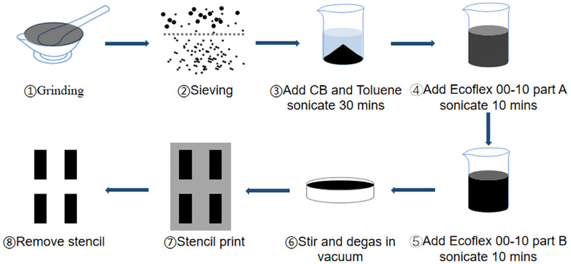
Each CB-PDMS sample regardless of carbon-black concentration was produced in the following manner (Fig. 4). Carbon black (Carbot, CAS#1333-86-4) of the proper particle size was prepared by gently grinding carbon granules in a ceramic mortar and sieving the resulting powder to 0.1 mm. Next, the appropriate amount of filtered powder to achieve the desired carbon-black concentration in the PDMS composite was dispensed into a clean beaker. Next, 10 mL of toluene was added to the carbon black and the beaker was sonicated for 30 min (Qsonica Q500 probe, 500W, 20 kHz, 30% duty cycle) to ensure thorough mixing. Next, Parts A and B of PDMS elastomer (Ecoflex 00–10, Smooth-On) were added to the beaker in that order, followed by a 10 min sonication. Ecoflex was used in the CB-PDMS layer because of its high elasticity and low hardness relative to other forms of PDMS. This was required because the addition of carbon-black reduced the elasticity of the composite structure. The CB-PDMS-toluene mixture was poured into an aluminum tray and magnetically stirred at room temperature to facilitate the evaporation of the toluene. Once the mixture became too viscous to stir, it was transferred to a vacuum desiccator and exposed to a vacuum environment until the composite reached a toluene concentration below 3%. At this point, the composite was cast into final dimensions, fully cured at room temperature, and completely degassed.
Fig. 4.
Process flow of CB-PDMS fabrication
B. Electrical Characterization
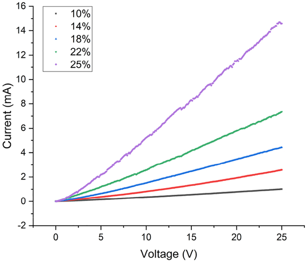
For resistance testing, 10 rectangular samples 20 mm in length, 5 mm in width and 0.1 mm in thickness were fabricated from each CB concentration group. Standard, two-point, current-voltage (I-V) measurements were made on each sample using a DC power supply (Keysight E3631A) and a picoammeter (Keithley 6485). Each sample was secured to a glass slide to ensure that there was no stretching or flexing during I-V sweeps. Electrical contact to each sample was made using standard probes. For the I-V measurements, the voltage was swept from 0 to 25 V in 0.1 V steps. The resistance was calculated from a linear fit of the I-V data. For each sample, five I-V sweeps were performed and an average resistance was calculated from the five individual resistances. Fig. 5 is a representative plot of an I-V sweep for composite samples from each of the CB concentration groups showing that each of the samples exhibits ohmic behavior.
Fig. 5.
I-V sweep for CB-PDMS samples with different CB concentrations.
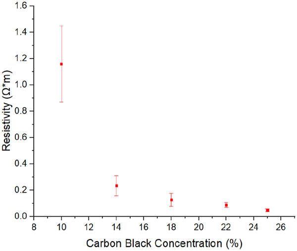
The resistivity of each test specimen was calculated from the average resistance measurements by assuming a uniform sample geometry. Fig. 6 is a plot of average resistivity versus carbon black concentration for the samples included in this study. The error bars represent the standard deviation in the measured data for 10 samples in each group. The data clearly showed a strong non-linear dependence of resistivity on carbon black concentration, ranging from 1.16 Ω*m for a concentration of 10% to 0.046 Ω*m at 25%. The resistivity changed by only 0.188 Ω*m when the carbon-black concentration increased from 14% to 25%. Because the percolation threshold for conductivity in CB-PDMS is in the range of 1–10% [35–36] the 10% carbon-black samples showed wide variance in resistivity. Conductivity is governed by the statistical likelihood of conductive paths formed in the composite, causing greater variance when near threshold.
Fig. 6.
Resistivity versus carbon-black concentration for CB-PDMS.
C. Mechanical Characterization
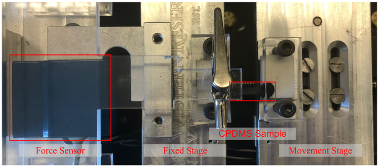
In order to characterize the mechanical properties of the CB-PDMS composites, samples from each group were subjected to a standard uniaxial tensile test. A photograph of our custom-built apparatus, which is capable of performing simultaneous I-V measurements during a tensile test, is shown in Fig. 7. For this particular test, test specimens from each group were fabricated into rectangular test coupons of the same dimensions used in the static resistance measurements. One side of each sample was mounted to a fixed stage which is connected to a commercialized force sensor (DPM-3, Transducer Techniques) to monitor applied force. The opposite side of each sample was mounted to a screw-driven movable stage which has a stepper motor that is controlled by a Labview program. The apparatus measures the applied force as the sample is elongated along its principal axis. Force measurements are made in increments of 5 μm. The instrument generates a force versus displacement curve for each test, and from this information, a stress versus strain curve is generated. The maximum applied strain for each test was capped at 50% to ensure that the measurements remained in the elastic regime. As such, the Young’s modulus of each sample can be determined directly from the slope of a fitted line to the stress-strain curve.
Fig. 7.
Photograph of the custom-built uniaxial tensile testing apparatus with a CB-PDMS sample mounted on the sample stage.
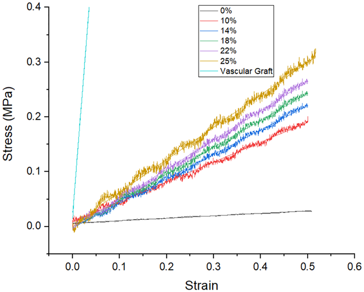
Fig. 8 presents stress-strain curves for representative CB-PDMS samples from each group as well as neat PDMS and an ePTFE vascular graft (GORE-TEX Stretch graft). From these plots, we find the Young’s modulus to range from a low of 45 kPa for neat PDMS to 592 kPa for a composite sample with a carbon-black concentration of 25%. The ePTFE graft had a uniaxial Young’s modulus of ~10.7 MPa, which is 20× to 230× less elastic than the PDMS samples.
Fig. 8.
Stress-strain measurement results for CB-PDMS composites with different CB concentration. Also included is the stress-strain plot for the ePTFE vascular graft.
D. CB-PDMS Strain Gauge Factor
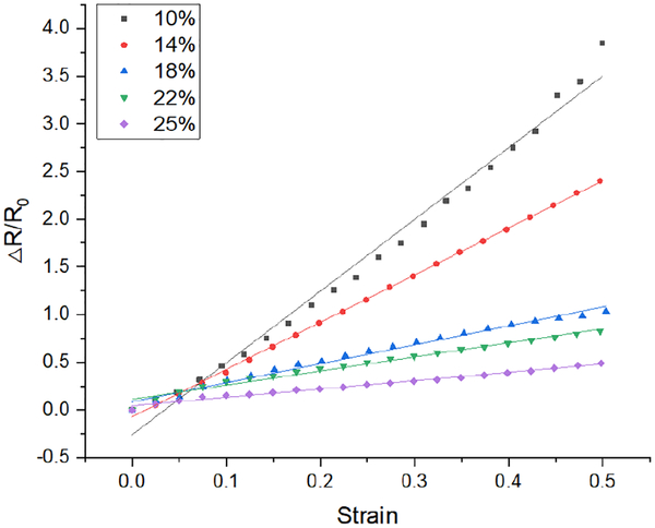
To evaluate the utility of CB-PDMS as a strain gauge material, conventional serpentine resistors from each group were fabricated and tested using the tensile testing apparatus. The fabrication method to create these structures is described in Section III. As with the aforementioned tensile tests, these samples were also subjected to tensile strains up to 50%. Fig. 9 shows plots of the relative change in resistance versus applied strain for samples from each of the five CB composition groups. All samples exhibit the linear behavior that is desired of high-quality strain gauges.
Fig. 9.
Relative change in resistance versus strain for CB-PDMS composites of different carbon-black concentrations.
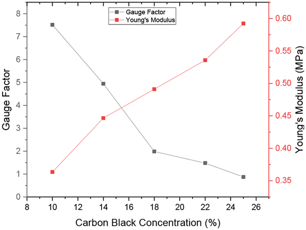
Fig. 10 shows plots of gauge factor and Young’s modulus as a function of carbon black concentration. The gauge factor decreased with increasing carbon black concentration from a high of 7.5 for a carbon-black concentration of 10% to a low of 0.87 for a concentration of 25%. In contrast, the Young’s modulus increased with increasing CB content, ranging from 364 kPa to 592 kPa for carbon-black concentrations between 10% and 25%. The FPS device requires a strain sensitive material that exhibits both a relatively high gauge factor, reasonably low stiffness and relatively low electrical resistivity. Considering the data shown in both Fig. 10 and Fig. 6, although the 10% CB-PDMS was the most stretchable and had the highest gauge factor, the uncertainty of the resistance was too large for a sensor application. The 14% CB-PDMS had high gauge factor, low Young’s modulus and low resistance variability, so it was selected for the FPS device.
Fig. 10.
Gauge factor and Young’s modulus for CB-PDMS as a function of carbon-black concentration.
E. Bending Test on Cylindrical Tubes
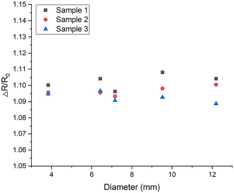
To investigate the effect of bending on resistance change of the sensor, 3 sensors were measured flat and after wrapping around different diameter tubes (Fig. 11).
Fig. 11.
Relative change in resistance versus bending radius. Resistance change was calculated relative to the flat sensor (infinite curvature diameter).
Bending increased the sensor resistance by 9–11%, with no clear dependence on radius of curvature. The resistance increase caused by bending indicates that the bending effect should be considered when designing an interface circuit for electronic readout.
F. Cyclic Tensile Testing of CB-PDMS Samples
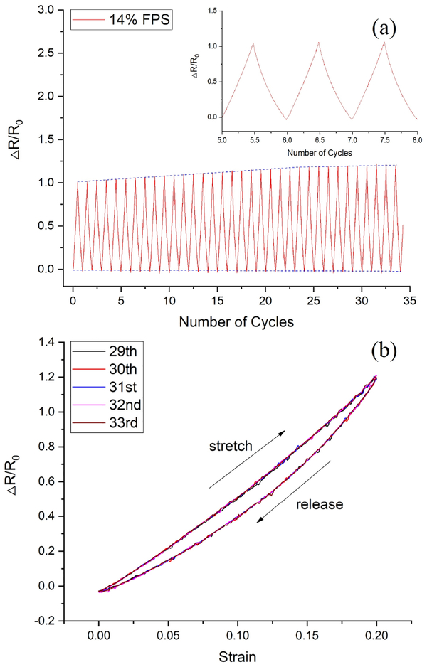
In order to evaluate the electrical and mechanical stability of the CB-PDMS under periodic loading, a cyclic tensile test was performed on a sample fabricated using a CB content of 14%. This test structure was subjected to cyclic loading over a strain range of 0 to 20%. The test was performed using the previously described tensile tester for 35 identical cycles. In this case, the tensile testing apparatus performed simultaneous measurements of both the applied force and the I-V characteristics as a function of sample displacement. From these data, plots of relative resistance versus loading cycle (Fig. 12a) and hysteresis loops (Fig. 12b) were generated. For this particular sample, the gauge factor using the data from cycles 5 to 8 was ~5. However, the gauge factor associated with data from cycles 25 to 30 increased to ~6. This suggests that the CB-PDMS undergoes a short burn-in period before stabilizing. Fortunately, the burn-in period resulted in an increase in gauge factor. The constant baseline of the data in Fig. 12a suggests that the unstrained resistance remains stable under cyclic loading, and that the increase in gauge factor is a result of an increase in resistance under mechanical load. It should be noted that this cyclic test was performed using maximum strain that greatly exceeds the maximum strain that will be experienced by the FPS device, which we estimate to be 1–10% for arteries, veins, or grafts (Table I) for flow rates and pressures in the physiologic range.
Fig. 12.
(a) Relative change in resistance as a function of load/unload cycles for a CB-PDMS sample with a carbon-black concentration of 14%. (b) Hysteresis effect of strain-resistance for 5 loops.
IV. FPS Design and Fabrication
An FPS device was designed to operate over a strain range of 0–20% to match the strain range arteries, veins, and synthetic grafts [7]. The FPS was constructed from two materials: 14% CB-PDMS composite, and MED-4210 medical PDMS (A-103, Factor-II). CB-PDMS and bulk PDMS were patterned while wet and cured together to improve bonding strength. The uncured CB-PDMS composite was prepared as described previously and the bulk PDMS was mixed conventionally, then degassed for 15 minutes in 28 inHg vacuum.
Sensor construction involved three steps: strain sensor patterning, electrical lead attachment, and overcoating. This produced a three-layer structure consisting of a CB-PDMS strain sensor pattern embedded between two structural PDMS layers. The structural PDMS layers provided waterproofing and mechanical support so the CB-PDMS strain sensor deformed isotropically during pulsation.
Sensor fabrication used stencil printing with 0.1 mm-thick mylar sheets laser cut into the required patterns for the FPS design. Each strain gauge was comprised of three, 0.1 mm-thick stripes that were 20 mm long, 1 mm wide, and spaced 1 mm apart. The sensor layer was 0.1 mm thick and included two, 4 mm2 contact pads. Conservative dimensions were used for this sensor fabrication; lithographic, micro-stamping, or polymer deposition methods could be used to create finer structures to improve strain sensitivity [21].
Sensor fabrication followed a simple process relying on PDMS-PDMS bonding during curing. First, a bulk PDMS structural layer was cast onto a quartz substrate in a 0.1-mm thick layer. Next the CB-PDMS sensing layer was stencil printed onto the uncured structural PDMS layer. This structure was cured in a vacuum oven at 60 °C for 15 minutes. Next, 0.2-mm diameter, PTFE-coated stainless-steel leads were attached to the CB-PDMS contact pads using silver epoxy (MG Chemicals 8330). A 0.1-mm encapsulating layer of bulk PDMS was applied on top of the CB-PDMS and epoxied leads and fully cured at 60°C for 30 minutes. This produced a waterproof FPS sensor exposing only biocompatible PDMS to the biologic environment. The FPS was mounted on an ePTFE vascular graft for in vitro testing and secured with PDMS film (Fig. 13).
Fig. 13.
Electrical contacts for the FPS were formed using stainless steel wires and silver epoxy (Top). The FPS was wrapped around a 6-mm vascular graft and secured with PDMS film for pressure-flow characterization (Bottom).
V. FPS Flow Sensing on Vascular Graft Phantom
A. Vascular graft phantom
An in vitro vascular flow loop was created based on prior reports of benchtop systems simulating blood flow through a vascular graft [37] (Fig. 14). The phantom used blood-mimicking fluid (BMF) to simulate the shear-thinning properties of human blood [38]. This solution consisted of 83.76% pure water, 10.06% pure glycerol, 3.36% dextran, 0.90% surfactant (Synperonic PE84), 0.1% sodium benzoate (preservative), and 1.8% polyimide particles. The water, glycerol, dextran, surfactant were first combined using magnetic stirring for one hour to dissolve the soluble materials. The polyimide particles were sieved through a 40 μm nylon mesh before being dispersed in the BMF. BMF was degassed and the particles dispersed in an ultrasonic bath for 15 minutes.
Fig. 14.
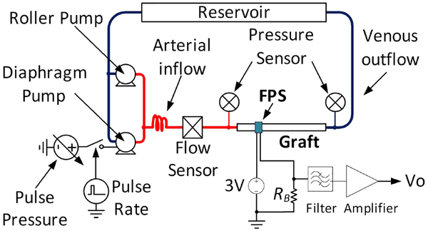
Schematic of the pulsatile graft flow circuit used for FPS in vitro test, after [25].
The system used a peristaltic roller pump (Cole Parmer Masterflex L/S 07522) and a variable-voltage diaphragm pump (Shurflo 4008) to produce arterial pressure waveforms. A vascular graft was connected between the high pressure and low pressure systems of the phantom to simulate an arteriovenous graft such as those used for hemodialysis vascular access. Low resistance pressure sensors (Pendotech PREPS-N-50) monitored the graft inlet (arterial) and outflow (venous) pressures and an electromagnetic flow meter (Omega FMG90) measured pulsatile and average flow rate.
In all experiments the roller pump was set to a constant 300 mL/min flow to set the diastolic pressure and the diaphragm pump was pulsed at 10% duty cycle to simulate a systolic pulse [39]. Pulsatile pressure was controlled by varying the diaphragm pump voltage from 3–12 V. A data acquisition system (National Instruments cDAQ-9178) controlled by National Instruments Labview software was used to record pressure and flow sensors, and to control the pulsatile pump at 60 beats per minute. Before all recordings, pumps were run for 30 minutes to homogenize the BMF and to saturate the vascular graft in fluid by driving out air from the pores.
B. In vitro FPS response speed
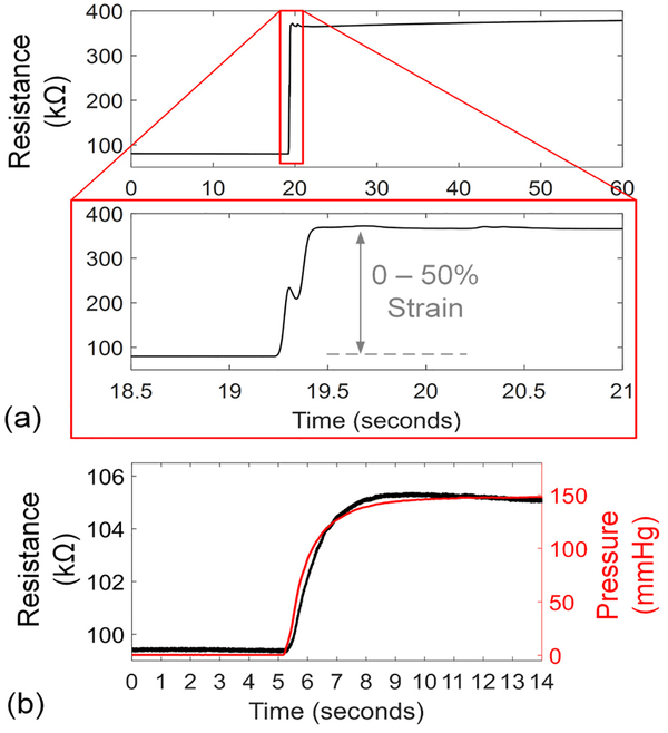
The response speed of the 14% CB-PDMS FPS was tested in in free air and in vitro. For free air response, the FPS was mounted horizontally with one end clamped. The other end was attached to a motion stage which was rapidly moved to produce 50% strain in the FPS (Fig. 15a). In this test the FPS demonstrated an average resistance change of 1.42 kΩ/ms, or 0.25% strain per millisecond. A dual-phase response was observed where the FPS reacted quickly to the initial strain change, reaching 90% of the final value within 200 ms. Then, a slower settling occurred due to mechanical relaxation within the polymer composite. For pulsatile blood flow monitoring this issue can be mitigated by AC-coupling sensor readings.
Fig. 15.
Step response of the FPS to 0–50% strain change in free air (a) with average strain response of 0.25%/ms. When tested in vitro on a 6-mm vascular graft with 0–1,100 mL/min change in flow, the response time constant of 0.89 s was produced by the graft wall expansion rate.
The FPS in vitro response speed was validated by wrapping the device around a 6-mm diameter thin-wall vascular graft (GORE-TEX stretch graft, W.L Gore & Associates). In this arrangement, the FPS response speed was damped by the time for the graft to expand under a sudden pressure change (Fig. 15b). A 140-mmHg pressure step was created with a flow change of 0–1,100 mL/min generated by the pumps. The FPS measured the step change in graft diameter with a time constant of 0.89 s.
C. In vitro pressure and flow sensing using FPS
The 14% CB-PDMS FPS was mounted on a 20-mm long, 6-mm diameter thin-wall vascular graft (GORE-TEX stretch graft, W.L Gore & Associates). The graft was pressurized at 180 mmHg when the FPS was applied to avoid kinking and to ensure intimate connection. The FPS was wrapped around the graft and secured in place with a 0.1-mm thick PDMS film which was wrapped around the FPS-graft structure. Test leads were connected to a reference 100 kΩ resistor and to a 3 V power supply to form a half bridge configuration. The voltage across the reference resistor was lowpass filtered to 5 Hz using a 4th-order analog Butterworth filter (Stanford Research Systems SIM965), and the filtered signal was amplified by 10× using a precision amplifier (Stanford Research Systems SIM910). Data recordings from the FPS, flow, and pressure sensors on the vascular phantom were sampled at 100-Hz using a data acquisition system (National Instruments cDAQ-9178).
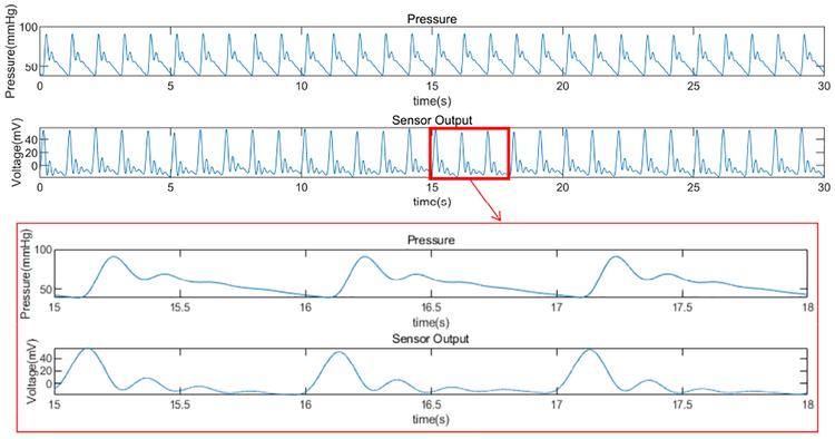
The FPS was tested over graft flows within the common physiologic range (0 – 1,100 mL/min). The FPS strain response varied periodically in each simulated cardiac cycle, with peaks correlating with the main systolic pulse and dicrotic notch (Fig. 16). Although the FPS waveform could be used to assess hemodynamic waveform shape or pulsatile phases, we simply calculated RMS amplitude of the resulting FPS signal. The RMS value was proportional to total fluid flow and pressure for each level of pump power.
Fig. 16.
Representative hemodynamic pressure waveform and FPS output waveform for 14% CB-PDMS FPS. The vascular phantom controlled for systolic pulse amplitude, diastolic pressure, and dicrotic notch (secondary peak after systole). Strong correlation in systolic, diastolic and dicrotic portions were seen in the FPS waveform.
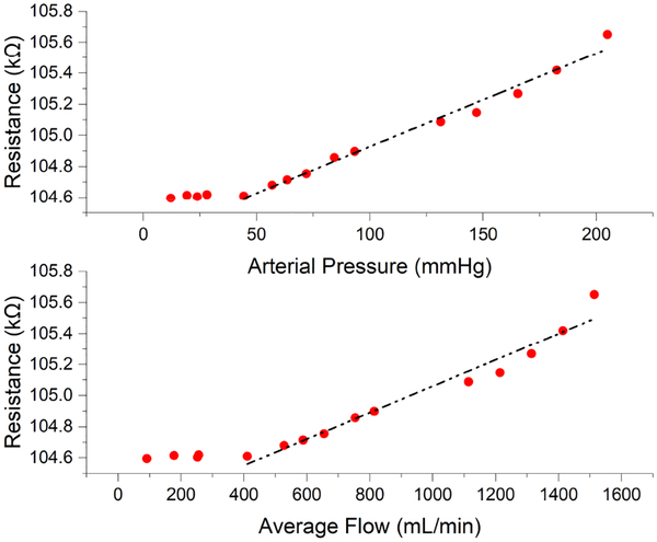
The amplitude of the FPS signal was strongly correlated with arterial pressure and graft flow rate, suggesting that graft diameter expansion causes significant strain changes in the FPS (Fig. 17). Below a threshold of approximately 30 mmHg (flow < 400 mL/min) pressure in the graft was too low to distend the graft walls. At pressures above this inflection point (e.g. in the normal range of arterial pressures >30 mmHg), a linear response to flow and pressure was obtained. The FPS errors were obtained by calculating the offset of the data points from the fitting curves. The RMS errors were 4.8 mmHg (3.0%) and 51.7 ml/min (5.2%) for pressure and flow. The maximum errors for pressure and flow were 15.3 mmHg (9.6%) and 182.7 ml/min (18.5%), which occurred at the highest pressure and flow values in the test range. Therefore, the reliability of the FPS working in high pressure and flow rate range should be studied carefully in the future.
Fig. 17.
FPS response relative to arterial pressure and graft flow. The FPS output correlated with arterial pressure, with a linear response above 30 mmHg. Similar correlation to graft flow was observed, with linear response to physiologic flows in functional grafts.
D. In vitro FPS stability
To determine the in vitro stability of the FPS, 960 mL/min pulsatile flow was maintained in the vascular graft for 20 minutes (Fig. 18a, b) with physiologic pulse pressures (170 mmHg systolic, 60 mmHg diastolic). The FPS maintained a relatively constant response throughout this test of over 1,100 cardiac cycles. Extracted peak-to-peak values per cycle showed a mean FPS resistance change of 0.94 kΩPP, standard deviation (σ) of 26.2 ΩPP, and a coefficient of variation (CV) of 2.8% (Fig. 18c). This test demonstrated stable in vitro response over hundreds of cardiac cycles with input-referred FPS sensitivity of 8.0 Ω/mmHg. Random variation in FPS output showed cycle-to-cycle flow measurement within ±24 mL/min and pulse pressure accuracy within ±2.9 mmHg.
Fig. 18.
Measured results of a 14% FPS on the vascular graft for over 1,100 cardiac cycles showed good stability and repeatability (a), with 2.8% RMS variation in peak-to-peak value (b).
VI. Discussion
This study provided an overview of CB-PDMS conductivity and gauge factor as a function of carbon black particle percentage but did not perform microstructure analysis as others have [40–41]. Scanning electron microscopy could be used to quantify carbon black particle distribution, which could further improve sensor performance. Our results suggest a conductivity percolation threshold below 10% for CB-PDMS which agrees with previous findings [35–36]. We also found that 10% CB-PDMS had a large variance in resistivity, possibly because it was near the percolation threshold for conductivity for this carbon black particle size. Our results also showed that CB-PDMS had a “burn in” period over which the gauge factor stabilized. While the gauge factor improved and stabilized over 1,100 cardiac cycles, we have not shown stability of gauge factor to the level needed for long-term clinical monitoring. Our results also showed that a thin CB-PDMS sensor can achieve very fast strain response speeds up to 0.25 % per ms, but a long relaxation time at large strain changes was observed. However, because cardiac cycles are repetitive this issue did not affect performance of the FPS when sensing pulsatile flow.
The FPS is intended for surgical implantation along with vascular graft implantation or endovascular repair. In this situation, it could be wrapped around a blood vessel in the same manner as a Cook-Swartz probe [42]. Unlike this probe, which uses a transcutaneous wire that needs to be removed after several days, the FPS could be coupled to a wireless transceiver for long-term monitoring of vessel patency. Clinical guidelines for graft monitoring recommend that reduction in blood flow by 25%, or flow below 600 mL/min is a threshold for surgical intervention to prevent thrombosis [8]. Interestingly, our results showed a distinctive change in sensor response starting at about 500 mL/min flow rate in a vascular graft, due to lack of wall distension under this flow rate. Above 500 mL/min, our results indicated that the FPS can measure blood pressure and flow within 4.8 mmHg and 51.7 mL/min respectively, suggesting that a 50% drop would be identifiable.
Several issues remain for future investigation. Future in vivo studies are needed to validate the sensor accuracy over longer implant periods. The initial 30 days after implant are critical for monitoring, but sensors must potentially remain stable for years. Concerns for CB-PDMS materials include temperature stability, tissue ingrowth, and biocompatibility. While the human body maintains temperature in a narrow range of +/− 3 °C, this could be sufficient to disrupt sensor baseline resistance. Temperature drift could be mitigated by using unstrained CB-PDMS reference resistors in a bridge circuit. Tissue growing between the FPS and the vessel could disrupt the sensor response, but this concern would be limited for biocompatible materials. CB-PDMS is biocompatible depending on carbon black granule size [43–44]. The FPS uses pure medical-grade PDMS as outer encapsulation layers to shield the CB-PDMS sensor layer from cells, but long-term in vivo demonstrations will be needed to assess device stability.
VII. Conclusion
This study demonstrated the potential for using piezoresistive, biocompatible polymers for dynamic strain sensing applications over large strain ranges. Because CB-PDMS composites have large strain ranges and elastic moduli lower than natural blood vessels and synthetic grafts, they are well suited to long-term monitoring of vascular pulsation. Our work suggests that an optimum concentration of 14% CB nanoparticles can produce accurate, stable polymeric strain sensors with comparable gauge factor to thin metal films. In vitro testing of flexible pulsation sensors wrapped on conventional ePTFE vascular grafts showed that graft pressure and flow can be measured over hundreds of cycles of pulsatile blood flow. Because the CB-PDMS pulsation sensors had good sensitivity and a relatively low sensor resistance, they can be interfaced to low-power implanted electronics for chronic monitoring applications.
ACKNOWLEDGMENTS
The authors thank Dr. Yongkun Sui at Case Western Reserve University for his assistance with the tensile tests.
This work was supported by RX001968–01 from the US Dept. of Veterans Affairs Rehabilitation Research and Development Service, the Advanced Platform Technology Center, and Case Western Reserve University. The contents do not represent the views of the US Government.
Biographies

Hao Chong was born in Tianjin, China, in 1993. He received the B.E. degree in measuring and control technology and instruments from Tianjin University, Tianjin, China, in 2015. He is currently pursuing the Ph.D. degree in electrical engineering at Case Western Reserve University, Cleveland, Ohio, USA.
He has also been a Research Assistant with the Louis Stokes Cleveland VA Medical Center in Cleveland, Ohio, USA since August 2017. His research interests include the development of biomedical sensors using carbon black-based polymer materials, fabrication of electrochemical sensors using inkjet printing technology, and non-hermetic packaging technologies for flexible and implantable medical devices.

Jiongcheng Lou was born in Shanghai, China, in 1999. He is currently pursuing a Bachelor of Science degree in electrical engineering at Case Western Reserve University, Cleveland, Ohio, USA.
His research interests include developing, fabricating, and testing polymer and carbon-based biomedical sensors. He looks forward to leverage his knowledge and skills to further contribute to biomedical circuit research.

Kath M. Bogie received the BSc(Hons) degree in Metals and Materials Technology from the University of Manchester Institute of Science and Technology (UMIST) and a D.Phil in Biomedical Engineering from the University of Oxford, England.
She is a biomedical engineer committed to pursuing patient-centered translational research. She currently holds appointments as Associate Professor in the Dept of Orthopaedics at Case Western Reserve University (CWRU) and as Research Career Scientist at the Louis Stokes Cleveland Dept of Veterans Affairs Medical Center, where she is also Director of Health Maintenance and Monitoring within the Advanced Platform Technology Center. She serves on several editorial boards, is on the Board of the Wound Healing Society and is a member of the RESNA Standards Committee on Wheelchair and Related Seating, and holds patents for wound healing technology. She has published over 60 papers and book chapters and given multiple national and international presentations.

Christian A. Zorman received a B.S. cum laude in physics and a B.A. cum laude in economics from the Ohio State University in 1988, followed by M.S. and Ph.D. in physics from Case Western Reserve University in 1991 and 1994, respectively. He joined the MEMS program at CWRU in 1994 as a Research Associate, was promoted to Senior Research Associate in 1997 and Researcher in 2000. From 2000 to 2002, he held an appointment as Adjunct Assistant Professor in the Department of Electrical Engineering and Computer Science.
He joined the EECS faculty at CWRU in 2002 as an Associate Professor and currently holds an appointment as Professor with secondary appointments in the Departments of Biomedical Engineering and Mechanical and Aerospace Engineering. In 2018, Prof. Zorman was awarded the Leonard Case Jr. Professor of Engineering. Dr. Zorman is also a Research Associate at the Louis Stokes Cleveland VA Medical Center where he serves as Co-Director of Research and Scientific Affairs for the Advanced Platform Technology Center of Excellence. He currently serves as Faculty Director of the Microfabrication Laboratory at CWRU. Prof. Zorman has authored over 300 peer-reviewed technical publications, is a Senior Member of IEEE and chairman of the MEMS Technical Group in the American Vacuum Society (AVS). He serves as a Senior Editor for IEEE Sensors Letters. In 2017, he was elected a Fellow of the AVS for pioneering work in the development of CVD deposition techniques and mechanical characterization of silicon carbide thin films for harsh environment MEMS. In 2009, Professor Zorman received the John S. Diekhoff Award for Excellence in Graduate Mentoring, CWRU’s highest honor in this area. His research centers on the development of novel, enabling materials and the requisite processing techniques for micro- and nanoelectromechanical systems with an emphasis on applications in challenging environments. Since September 1, 2017 Prof. Zorman has been serving as Associate Dean for Research in the Case School of Engineering.

Steve J.A. Majerus (M’07–SM’16) received the B.S. and M.S. degrees in electrical engineering from Case Western Reserve University (CWRU) in 2007 and the Ph.D. degree in electrical engineering with a focus in integrated circuit design and implantable medical devices from the same university in 2014.
He was a Biomedical Engineer in the Advanced Platform Technology Center (APTC) at the Louis Stokes US Dept of Veterans Affairs (VA) Medical Center in Cleveland, Ohio, USA from 2007 to 2015. He also worked as a Senior Research Associate at CWRU in wide bandgap SiC JFET ASICs from 2014 to 2016 and as a high-temperature aeronautic CMOS ASIC designer for Scientific Monitoring, Inc. from 2010 to 2014. Since 2015, he has been a Research Scientist with the APTC. He also holds a secondary appointment in the Nephrology Service of the Northeast Ohio VA Healthcare System after receiving the Louis Stokes Research Fellowship Award in 2018. He has contributed to more than 40 peer-reviewed publications, and holds 6 issued or pending patents. His current research interests include passive acoustic detection of vascular access stenosis, temporal-spectral signal processing of blood sounds, flexible microphone arrays, implantable ultra-low-power bio-sensors, and flexible sensor systems for cardiovascular health monitoring.
Contributor Information
Hao Chong, Department of Electrical Engineering and Computer Science, Case Western Reserve University, Cleveland, OH, 44106, USA.
Jiongcheng Lou, Department of Electrical Engineering and Computer Science, Case Western Reserve University, Cleveland, OH, 44106, USA.
Kath M. Bogie, Department of Orthopaedics, Case Western Reserve School of Medicine, Cleveland, OH, 44106, USA Advanced Platform Technology Center, Louis Stokes Cleveland Veterans Affairs Medical Center, Cleveland, OH, 44106, USA.
Christian A. Zorman, Department of Electrical Engineering and Computer Science, Case Western Reserve University, Cleveland, OH, 44106, USA; Advanced Platform Technology Center, Louis Stokes Cleveland Veterans Affairs Medical Center, Cleveland, OH, 44106, USA.
Steve J.A. Majerus, Advanced Platform Technology Center, Louis Stokes Cleveland Veterans Affairs Medical Center, Cleveland, OH, 44106, USA.
REFERENCES
- [1].Greenwald S and Berry C, “Improving vascular grafts: the importance of mechanical and haemodynamic properties,” Journal of Pathology, vol. 190, pp. 292–299, 2000. [DOI] [PubMed] [Google Scholar]
- [2].Singh N et al. Singh, “Factors associated with early failure of infrainguinal lower extremity arterial bypass,” Journal of Vascular Surgery, vol. 47, pp. 556–561, 2008. [DOI] [PubMed] [Google Scholar]
- [3].Mills JL et al. , “The natural history of intermediate and critical vein graf stenosis: Recommendations for continued surveillance or repair,” Journal of Vascular Surgery, vol. 33, pp. 273–280, 2001. [DOI] [PubMed] [Google Scholar]
- [4].Koobatian M, Koenigsknecht C, Row S, Andreadis S and Swartz D, “Surgical Technique for the Implantation of Tissue Engineered Vascular Grafts and Subsequent In Vivo Monitoring,” Journal of visualized experiments: JoVE, p. e52354–e52354, 2015. [DOI] [PMC free article] [PubMed] [Google Scholar]
- [5].Oresanya LM et al. “Factors associated with primary vein graft occlusion in a multicenter trial with mandated ultrasound surveillance,” Journal of Vascular Surgery, vol. 59, p. 996–1002, 2014. [DOI] [PubMed] [Google Scholar]
- [6].Norgren L et al. , “Inter-Society Consensus for the Management of Peripheral Arterial Disease (TASC II),” Journal of Vascular Surgery, vol. 45, pp. S5–S67, 2007. [DOI] [PubMed] [Google Scholar]
- [7].Roll S et al. , “Dacron® vs. PTFE as bypass materials in peripheral vascular surgery – systematic review and meta-analysis,” BMC Surg, vol. 8, no. 22, pp. 1–8, 2008. [DOI] [PMC free article] [PubMed] [Google Scholar]
- [8].Allon Michael et al. “Monitoring and surveillance of hemodialysis arteriovenous grafts to prevent therombosis,” in UpToDate, Post Ted.W., Ed., Waltham, MA: UpToDate, 2014. [Google Scholar]
- [9].Chen X, Brox D, Assadsangabi B, Hsiang Y and Takahata K, “Intelligent telemetric stent for wireless monitoring of intravascular pressure and its in vivo testing,” Biomedical Microdevices, vol. 16, no. 5, pp. 745–759, 2014. [DOI] [PubMed] [Google Scholar]
- [10].Cheong JH et al. , “An Inductively Powered Implantable Blood Flow Sensor Microsystem for Vascular Grafts,” IEEE Transactions on Biomedical Engineering, vol. 59, no. 9, pp. 2466–2475, 2012. [DOI] [PubMed] [Google Scholar]
- [11].Sarkar S, Salacinski H, Hamilton G and Seifalian A, “The Mechanical Properties of Infrainguinal Vascular Bypass Grafts: Their Role in Influencing Patency,” European Journal of Vascular and Endovascular Surgery, vol. 31, pp. 627–636, 2006. [DOI] [PubMed] [Google Scholar]
- [12].Dario P, Richardson P and Galletti P, “Monitoring of prosthetic vascular grafts using piezoelectric polymer sensors.,” Transactions of the American Society of Artificial Internal Organs, vol. 29, pp. 318–22, 1983. [PubMed] [Google Scholar]
- [13].Neville RF, Gupta SK and Kuraguntla DJ, “Initial in vitro and in vivo evaluation of a self-monitoringprosthetic bypass graft,” Journal of Vascular Surgery, vol. 65, no. 6, pp. 1793–1801, 2017. [DOI] [PubMed] [Google Scholar]
- [14].Gupta SK et al. , “Use of a piezoelectric film sensor for monitoring vascular grafts,” The American Journal of Surgery, vol. 160, no. 2, pp. 182–186, 1990. [DOI] [PubMed] [Google Scholar]
- [15].Natta L et al. , “Soft and fexible piezoelectric smart patch for vascular graft monitoring based on Aluminum Nitride thin film,” Sci Reports, vol. 9, p. 8392, 2019. [DOI] [PMC free article] [PubMed] [Google Scholar]
- [16].Mehdian M and Rahnejat H, “Blood flow measurement using a highly filled carbon polymer sandwich sensor and an elasto-pseudo compressible vascular flow,” Proceedings of the Institution of Mechanical Engineers, Part H: Journal of Engineering in Medicine, vol. 210, no. H4, pp. 289–296, 1996. [DOI] [PubMed] [Google Scholar]
- [17].Byrom MJ, Ng MK and Bannon PG, “Biomechanics and biocompatibility of the perfect conduit—can we build one?,” A of Cardiothor Surg, vol. 2, no. 4, pp. 435–443, 2013. [DOI] [PMC free article] [PubMed] [Google Scholar]
- [18].Gozna ER, Mason WF, Marble AE, Winter DA and Dolan FG, “Necessity for elastic properties in synthetic arterial grafts,” Can J Surg, vol. 17, pp. 176–179, 1974. [PubMed] [Google Scholar]
- [19].French RJ, O’Brien JP, Sparkes GL and Lalonde DH, “Free flap monitoring using an implantable Doppler probe,” Canadian Journal of Plastic Surgery, vol. 9, no. 6, pp. 233–238, 2001. [Google Scholar]
- [20].Liu C-X and Choi J-W, “Analyzing resistance response of embedded PDMS and carbon nanotubes composite under tensile strain,” Analyzing resistance response of embedded PDMS and carbon nanotubes, vol. 117, pp. 1–7, 2014. [Google Scholar]
- [21].Majerus SJA, Dunning J, Potkay J and Bogie K, “Flexible, structured MWCNT/PDMS sensor for chronic vascular access monitoring,” in Internal IEEE Sensors Conference, Orlando, 2016. [DOI] [PMC free article] [PubMed] [Google Scholar]
- [22].Khan S, Tinku S, Lorenzelli L and Dahiya RS, “Flexible Tactile Sensors Using Screen-Printed P(VDF-TrFE) and MWCNT/PDMS Composites,” IEEE Sensors Journal, vol. 15, no. 6, pp. 3146–3155, 2015. [Google Scholar]
- [23].Liu C-X and Choi J-W, “Strain-Dependent Resistance of PDMS and Carbon Nanotubes Composite Microstructures,” IEEE Transactions on Nanotechnology, vol. 9, no. 5, pp. 590–595, 2010. [Google Scholar]
- [24].Hassouneh SS, Yu L, Skov AL and Daugaard AE, “Soft and flexible conductive PDMS/MWCNT composites,” Journal of Applied Polymer Science, vol. 134, pp. 44767–44776, 2017. [Google Scholar]
- [25].Majerus SJA et al. , “Vascular Graft Pressure-Flow Monitoring Using 3D Printed MWCNT-PDMS Strain Sensors,” in IEEE Engineering in Medicine and Biology Conference, Honolulu, 2018. [DOI] [PMC free article] [PubMed] [Google Scholar]
- [26].Santana D and Armentano R, “Reduced Elastic Mismatch Achieved by Interposing Vein Cuff in Expanded Polytetrafluoroethylene Femoral Bypass Decreases Intimal Hyperplasia,” Artificial Organs, vol. 29, no. 2, pp. 122–130, 2005. [DOI] [PubMed] [Google Scholar]
- [27].Hertzberg B et al. , “Sonographic assessment of lower limb vein diameters: implications for the diagnosis and characterization of deep venous thrombosis,” Am J of Roentgenology, vol. 168, no. 5, pp. 1253–1257, 1997. [DOI] [PubMed] [Google Scholar]
- [28].Chandran KB, Gao D, Han G, Baraniewski H and Corson JD, “Finite-element analysis of arterial anastomoses with vein, Dacron and PTFE graffs,” Med Biol Eng Comp, vol. 30, no. 4, pp. 413–418, 1992. [DOI] [PubMed] [Google Scholar]
- [29].Ahlqvist J, “Atherosclerosis, and Newton, Poiseuille, Reynolds and Prandtl,” Medical Hypotheses, vol. 57, no. 4, pp. 446–452, 2001. [DOI] [PubMed] [Google Scholar]
- [30].Jindal K, Chan CT, Deziel C, Hirsch D, Soroka SD, Tonelli M and Culleton BF, “Vascular Access,” J Am Soc Neph, vol. 17, no. 3, pp. 16–23, 2006. [DOI] [PubMed] [Google Scholar]
- [31].Hall JE, “Role of the Kidneys in Long-Term Control of Arterial Pressure and in Hypertension,” in Guyton and Hall Textbook of Medical Physiology, Philadelphia, Elsevier, 2016, pp. 227–243. [Google Scholar]
- [32].Jørgensen C and Paaske W, “Physical and Mechanical Properties of ePTFE Stretch Vascular Grafts Determined by Time-resolved Scanning Acoustic Microscopy,” Euro J Vasc Endovasc Surg, vol. 15, no. 5, pp. 416–422, 1998. [DOI] [PubMed] [Google Scholar]
- [33].Li W, “Biomechanical property and modelling of venous wall,” Progress in Biophysics and Molecular Biology, vol. 133, pp. 56–75, 2018. [DOI] [PubMed] [Google Scholar]
- [34].Lindström SB et al. , “Computer-Aided Evaluation of Blood Vessel Geometry From Acoustic Images,” J of Ultrasound Med, vol. 37, pp. 1025–1031, 2018. [DOI] [PubMed] [Google Scholar]
- [35].Ruhhammer J et al. “Highly elastic conductive polymeric MEMS,” Sci Technol Adv Mater, Vols. 16, 015003, 2015. [DOI] [PMC free article] [PubMed] [Google Scholar]
- [36].Niu X et al. , “Characterizing and patterning of PDMS-based conducting composites,” Advanced Materials, vol. 19, pp. 2682–2686, 2007. [Google Scholar]
- [37].Nemati M et al. , “Application of full field optical studies for pulsatile flow in a carotid artery phantom,” Biomed Opt Expr, vol. 6, no. 10, p. 4037–4050, 2016. [DOI] [PMC free article] [PubMed] [Google Scholar]
- [38].Ramnarine KV, Nassiri DK, Hoskins PR and Lubbers J, “Validation of a New Blood-Mimicking Fluid For Use in Doppler Flow Test Objects,” Ultrasound in Medicine & Biology, vol. 24, no. 3, pp. 451–459, 1998. [DOI] [PubMed] [Google Scholar]
- [39].Elgendi M, “On the Analysis of Fingertip Photoplethysmogram Signals,” Current Cardiology Reviews, vol. 8, pp. 14–25, 2012. [DOI] [PMC free article] [PubMed] [Google Scholar]
- [40].Wu H, Feng L, Jiang A, Zhang B, “Effect of the processing of injection-molded, carbon black-filled polymer composites on resistivity,” Polymer Journal, vol. 43, pp. 930–936, 2011. [Google Scholar]
- [41].Chen Y et al. , “Super-hydrophobic, durable and cose-effective carbon black/rubber composites for high performance strain sensors,” Composites Part B, Vols. 176, 107358, 2019. [Google Scholar]
- [42].Guillemaud JP, Seikaly H, Cote D, “The Implantable Cook-Swartz Doppler Probe for Postoperative Monitoring in Head and Neck Free Flap Reconstruction,” Arch Otolaryngol Head Neck Surg, vol. 134, no. 7, pp. 729–734, 2008. [DOI] [PubMed] [Google Scholar]
- [43].Lin X et al. , “Mechanically durable superhydrophobic PDMS-candle soot composite coatings with high biocompatibility,” Journal of Industrial and Engineering Chemistry, pp. 79–85, 2019. [Google Scholar]
- [44].Lee C, Jug L and Meng E, “High strain biocompatible polydimethylsiloxane-based conductive graphene and multiwalled carbon nanotube nanocomposite strain sensors,” Applied Physics Letters, vol. 102, no. 18, e183511, 2013. [Google Scholar]


