Abstract
Movement impairments resulting from neurologic injuries, such as stroke, can be treated with robotic exoskeletons that assist with movement retraining. Exoskeleton designs benefit from low impedance and accurate torque control. We designed a 2 degree-of-freedom tethered exoskeleton that can provide independent torque control on elbow flexion/extension and forearm supination/pronation. Two identical series elastic actuators (SEAs) are used to actuate the exoskeleton. The two SEAs are coupled through a novel cable-driven differential. The exoskeleton is compact and lightweight, with a mass of 0.9 kg. Applied RMS torque errors were less than 0.19 Nm. Benchtop tests demonstrated a torque rise time of approximately 0.1 s, a torque control bandwidth of 3.7 Hz and an impedance of less than 0.03 Nm/deg at 1 Hz. The controller can simulate a stable maximum wall stiffness of 0.45 Nm/deg. The overall performance is adequate for robotic therapy applications and the novelty of the design is discussed.
Keywords: Biomechatronics, exoskeleton, rehabilitation robotics, upper extremity
I. Introduction
NEUROLOGICAL disorders such as stroke are one of the leading causes of long term disability worldwide and negatively affects quality of life [1]. Stroke survivors often experience movement impairments related to inability to activate muscles appropriately for the task [2, 3] and abnormal synergies between different muscle groups [4]. Current approaches to neurorehabilitation focus on task-specific repetitive movement practice and there is growing interest in robotic approaches that assist completion of movements and can enhance the effectiveness of the movement practice [5]. A large meta-analysis of 34 studies reported that use of upper extremity robots had advantages over other interventions in promoting recovery of strength, arm function and ability to perform activities of daily living [6].
Flexibility in designing treatment modes is increased with devices that can deliver accurate torque control over an appropriate range. For this application, the device must simulate a wide range of impedances, from highly transparent modes where the torques applied are negligible during “free” movements to higher stiffness modes for assisting movements. State-of-the-art rehabilitation robots include [7], [8], [9]. In the case of robots for planar end point movements, one approach is using large direct drive motors that drive a 2-DOF linkage [10]. However, there are many challenges to achieving adequate performance in upper extremity exoskeletons designed to support realistic reaching movements, which can have as many as 7-DOF. Achieving low impedance in “free” modes is particularly challenging where the mass and inertia of the robot links are often much larger than the mass and inertia of the human upper extremity. Gravity compensation is straightforward, but the dynamics of robot structure and actuators can only be partially cancelled by active compensation schemes [11]. When wearing an exoskeleton, the patient must adapt to added inertia and altered mass distributions, which may limit the effectiveness of the device as a training tool, when the goal is to improve the patient’s ability outside of the robot.
Additionally, the potential for a wearable exoskeleton is severely limited by the mass of many current designs. Exoskeletons commercially available or under development vary widely in terms of kinematics, redundancy level and actuation methods. Limpact utilizes hydraulic actuators, has a max torque of 36 Nm and weighs 8 kg [12]. The Armin III robot [13] uses DC motors and harmonic drives, and has a maximum moving mass of 7.06 kg. The Caden-7 weighs 6.8 kg, uses a combination of gears and cable drive transmissions to provide 62 Nm of peak torque [14]. These robots all have masses that far exceed the mass of the human upper extremity, which is approximately 5% of body-weight (~3.5 kg) [15].
In this paper, we describe the design and testing of the forearm component of an upper extremity robot called Ultra Low Impedance eXoskeleton (ULIX). This component actuates elbow flexion/extension (FE) and forearm supination/pronation (SP). The actuation of SP is particularly challenging because the axis of rotation is along the long axis of the forearm, so a mechanism is needed that allows rotation along this axis while avoiding the human forearm volume. Circular tracks are the most common solution, but actuation often leads to bulky structures and high friction. Our solution uses a novel cable driven differential that couples the elbow FE and SP joints, allowing load sharing of actuators, a compact design and application of pure SP torques, reducing loads and the size of structural members.
We adopted a second mass reduction method commonly used by wearable robotics devices that separate actuation hardware from worn elements through use of flexible Bowden cable transmissions, which have been used previously for elbow exoskeletons [16]. This approach provides a low worn mass, high torque capacity solution, which is ideal for our application. However, the friction in the cable can be problematic. To minimize the effects of Bowden cable friction and reflected inertia from gearing speed reduction, we used series elastic elements (SEE) to reduce impedance and mask the dynamics of the actuators from the user. However, maximum controllable stiffness is limited by the stiffness of the SEE. Bowden cables and SEE have been used effectively in other rehabilitation robots [17]. The design of our series elastic element is novel in that inexpensive linear springs are used in an arrangement that provides a nonlinear torsional spring, which gives better performance in free mode than linear springs. Additional novelty is related to the combination of these elements with a differential transmission for load sharing of two motors when actuating elbow flexion/extension and forearm supination/pronation. The usage of differentials is very common among robotic arms and in motor vehicles. Here we present a cable driven differential assembled around a user’s arm to produce a compact, form-fitting design. We believe we are the first group to integrate these features on an exoskeleton. The development of a coupled control algorithm for controlling the two motors is also novel. Performance of the system is described in bench-top testing and the effects of critical design choices will be discussed.
II. Design
We designed and constructed a novel 2-DOF exoskeleton for torque control at elbow flexion/extension (FE) and forearm supination/pronation (SP). We characterized system performance in benchtop testing with measurement of torque accuracy, bandwidth, step response time, impedance, max stiffness and 2-DOF coordination. Fig. 1 shows CAD models and a picture of the final prototype. The design specifications were maximum continuous torque of 10 Nm and 5 Nm of continuous torque in FE and SP, respectively, free mode impedance of .02 Nm/deg at 1 Hz, and maximum stiffness of .5 Nm/deg. The peak torque specifications are comparable to what was implemented in our prior clinical trial using the ARMin robot [18], but the target free mode impedance is significantly lower.
Fig. 1.
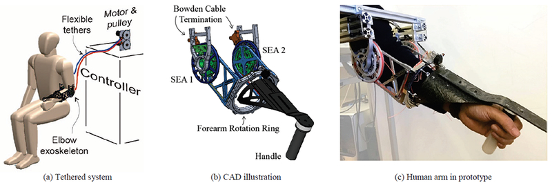
Mechanical design of the tethered system. (a) The system consists of off-board actuation and control hardware, flexible Bowden cable, and end-effector worn by the subject. (b) The end-effector has two independent series elastic actuator (SEA) on each side of the elbow. Their coordination provides the desired torque for elbow flexion/extension and supination/pronation. The two SEAs are connected together through the forearm ring, which is free to rotate relative to the frame. Carbon fiber extension and handle are bolted to the ring. (c) Prototype of exoskeleton.
A. Mechanical Design
To reduce the moving mass of the exoskeleton, we decided to use a cable transmission to locate the motors remotely, a strategy used by many wearable robotic devices [17, 19]. A novel cable-driven differential is integrated to couple the two DOFs and allows load sharing at each DOF. Each motor and gear can provide up to 13.8 Nm continuous torque (10 Nm, after reduction for gear friction), which is adequate for generating our target torques.
The transmission is compact and has the potential of becoming part of a wearable, mobile exoskeleton. Series elastic elements are included in the transmission to facilitate high accmacy torque control as well as low impedance. Most structural parts are aluminum alloy and made with computer numerical control (CNC) machining. Stress analysis and finite element analysis (FEA) simulations were done as part of the design process. Manual optimization was done to decrease weight. “I” shaped cantilever structures were widely used. To further reduce inertia and maintain structure rigidity, carbon fiber material was used for distal components supporting the handle. The overall weight is less than 0.9 kg.
1). Series elastic actuator module
Series elastic elements can be used to partially mask the reflected inertia and friction in motors and transmissions, allowing accurate torque control and low impedance [12, 17, 20–22]. We used two identical SEA modules (Fig. 2). A DC motor and gear head (RE40, GP42C, Maxon Motor AG, Sachsein, Switzerland) are selected to power each SEA. The torque of each motor is transmitted to the end-effector through a flexible Bowden cables (Lexco Cable Mfg., Norridge, IL) and high stiffness fishing line with 300 lbs capacity (Hercules Pro, LA, CA). We chose fishing line because it has high strength-to-diameter ratio. Also, from a practical standpoint, it is easy to tie knots on fishing line. For each SEA module, two Bowden cables and two lengths of fishing line are needed. One challenge is maintaining the tension in the fishing line while keeping the friction low. The motor pulley is a two-part assembly. The two parts can have relative motion. Each Bowden cable has two lengths of cable that are anchored to the assembly, with each length of cable anchored to only one part of the two-part assembly. Cable pretension is achieved by increasing the relative motion of the two parts. After desired pretension is achieved, the two parts are locked together manually with screws. Idler rollers are positioned so that the fishing lines wrap around nearly the entire circumference of the pulley, so that the radial force applied to the pulley shaft by the fishing line is minimized.
Fig. 2.
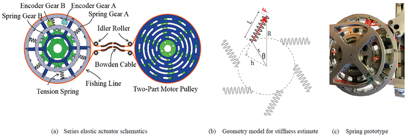
Mechanical design of the modularized series elastic actuator. (a) The series elastic element is a two-part assembly, consisting of a large wheel (blue) and a small wheel (green). These two wheels can rotate relative to each other within ±12° and they are connected by tension springs in a circular pattern, forming a custom torsion spring assembly. There are two digital encoders measuring the position of the big wheel and small wheel. On the motor end, a two-part motor pulley keeps the tension in the fishing line. The arched slots on the motor pulley ensure that the two pulley discs can be clamped down at any relative position. Idler rollers are used to regulate the winding of the fishing line on the pulley as well as the angle to enter the Bowden cable tether. (b) Simplified SEE geometry for calculating its stiffness. (c) A close up picture of the series elastic element.
On the end-effector end, a two-part torsion spring, made of aluminum 6061, acts as the elastic element. The component has two concentric wheels. The larger wheel is attached to the distal sections of the Bowden cables and converts the force in the Bowden cable to torque. The smaller wheel is attached to the distal forearm components. Linear springs connect the 2 wheels and provide a torsional stiffness between the 2 wheels. To measure the rotary deflection of the wheels relative to ground, we used spur gears laser cut from Delrin. Two incremental encoders (E4T, US Digital, Vancouver, WA) measure these rotations. Each encoder has a resolution of 0.25 degree, and the gear ratio further increases the resolution by 184:19 and 140:19, respectively, yielding a final resolution of 0.03 degree. The relative rotation of these 2 wheels represents the rotary deflection of the torsion spring.
The torsion spring can hold up to 12 tension springs and a variety of stiffness values can be achieved by choosing different type and number of spring. To ensure balanced forces, springs should be evenly spaced. Smaller spring free lengths and higher initial tension result in a more linear stiffness. For our application, however, an exponential-shaped profile was selected. To decrease impedance in free mode, we should use a low stiffness elastic element. In order to meet peak torque requirements, we need to use high stiffness elastic elements. This is our motivation to design a spring with nonlinear exponential stiffness. This way, near the neutral position the stiffness is low, and at high deformation the stiffness is high. This kind of stiffness better meets our design criteria compared to linear stiffness. The number and type of linear springs used was based on a design criteria of approximately 5 Nm torque at 12 deg of rotation at each SEA, in order to meet our target of 10 Nm of FE torque before the rotation limit of the SEA was reached.
2). Cable driven differential
Mechanical differentials can be found in robotic joints with gimble-like kinematics. The human elbow flexion/extension and forearm supination/pronation joints move as a gimble and motivated the use of a mechanical differential. There are several advantages of this approach compared to using two independent actuators. A more compact and lightweight design could be developed because of more balanced forces applied to the structure. Classical differentials usually contain bevel gears since right angle transmission is needed. Bevel gears have high weight, bulkiness, backlash and high customization cost. A novel cable-driven differential was presented in [23]. The structure is very compact and requires minimal mechanical parts. By carefully designing the path of the cable and its pre-tension, a low friction, small backlash right angle transmission can be achieved. We designed a similar mechanism and constructed a cable driven differential with 4 additional rollers to regulate the path of the cable, as shown in Fig 3.
Fig. 3.
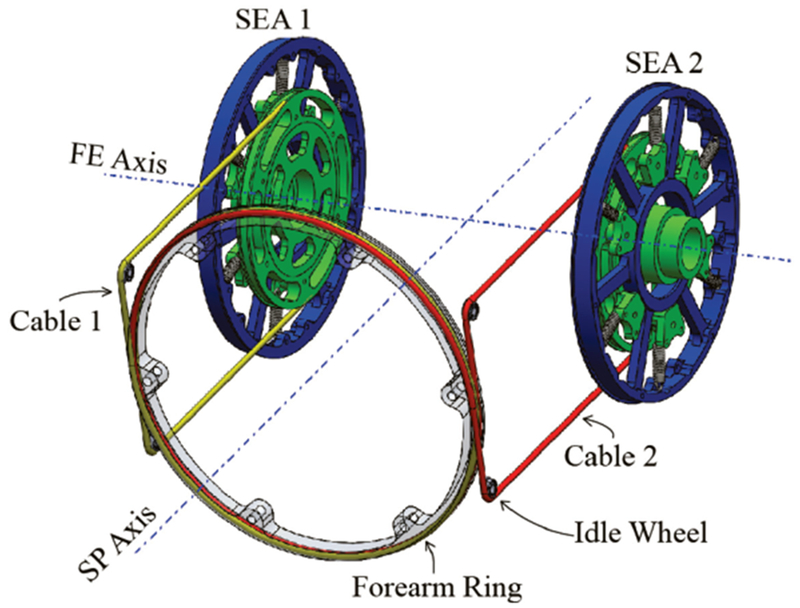
CAD illustration of cable-driven differential. Each SEA pulley (green) is tied to the forearm ring with cable (yellow and red).
For each side of the differential, two lengths of cable tie the SEA to the forearm ring, forming a closed loop. When the two SEAs rotate in the same direction, the two SEAs are locked to each other through the ring, and the exoskeleton will rotate around FE axis with no SP rotation. When the two SEAs rotate in opposite direction, the forearm ring will rotate around SP axis with no FE rotation. It is clear that undesirable coupling between DOF is possible if control of the SEA units is not coordinated.
Supination/pronation range of motion is designed to be at least 180°, or 90° for supination and 90° for pronation. Considering a gear ratio of R= 1.78, each SEA needs to be able to rotate ± 159°. In the differential design, each SEA contributes to motion at both the FE and SP DOFs, so must accommodate the full ROM at these DOF. To satisfy FE only motion (no SP motion), each SEA needs to have a ROM of 0 to 135 deg. To satisfy SP only motion (no FE motion), each SEA needs to have a ROM of −159 to 159 deg. Therefore to satisfy FE motion and SP motion at the same time, the overall ROM of each SEA need to be −159 to 294 deg. The two cables are tied to each SEA and forearm ring with enough revolutions to satisfy range of motion requirements.
Torque generated by the two SEA modules, T1, and T2, contribute to FE torque and SP torque in the following manner:
| (1) |
| (2) |
where TFE is FE torque, TSP is SP torque, and R=1.78 is the gear ratio between the forearm ring and SEA.
The forearm ring is a custom 4-point-contact ball bearing. The outer ring of the bearing is fixed to the forearm frame and the inner ring can rotate freely around SP axis and is connected to the handle. To reduce weight, the 4-piece bearing was CNC milled from aluminum 7075. And the ball-contact surface was polished by hand. The balls, however, are hardened alloy steel. An aluminum-steel contact is not the best option because of possible deformation of the aluminum surfaces. We used undersized plastic balls in between every two steel balls to further reduce weight and keep steel balls evenly spaced. The two sets of cables enter the ring with 180 degree offset. They each wrap 180 degree to a tie-down point (so there’s not sliding between the ring and the cable), then continue to wrap another 180 degree to exit the ring. This arrangement is similar to the shape of a DNA double helix model. It has two chains winding around each other but has no interference. Not only does this minimizes the overall width of the winding, but also ensures that the pretension in the two lengths of cable are perfectly balanced, causing no moment or force on the bearing.
B. Control
A physical model of the system is shown in Fig. 4. The physical model consists of three mass-spring-damper modules. The motor pulley is connected to the series elastic element through Bowden cables, and the series elastic element is connected to the handle through the cables in the differential mechanism. The SEE stiffness was approximately 0.2 Nm/deg near its neutral position. We measured the torsional stiffness of the pulley and Bowden cable assembly and found it to be 1.85 Nm/deg, more than 9 times stiffer than the SEE. This high stiffness was achieved by pretensioning the cable assembly. The two encoders measure the angular displacement of the series elastic element. Their difference is the spring deflection, which we used to calculate spring torque. The SEA encoders that measure the angles of the large (blue) and small (green) pulley wheels (Fig. 3) can be used to measure FE and SP angles for feedback PID control. SP angle is given by the angle of the small pulley wheel divided by the gear ratio of 1.78. When we pretensioned the differential cables to a high force, performance in free mode was poor due to stiction in the differential cable routing system and an effective SP stiffness that was 3.2 times higher than FE stiffness. During movement onset, the feedback error terms in the PID controller do not increase until stiction is overcome and the small pulley wheel rotates relative to the larger wheel, which is resisted by the high SP stiffness of the SEA. To improve performance, we decreased the tension in the differential cables to a low level and added a 5th encoder to measure the SP angle directly from the angle of the forearm ring (Fig. 3). When the human attempts SP movement, this is measured by the 5th encoder and there is very little initial resistance because of slack in the cables. During movement onset, we measured a change in the 5th encoder signal approximately 25ms earlier than in the SEA encoders. Error derived from the 5th encoder is differentiated into a velocity error term that works in parallel with the PID controller. The net result is a velocity error that rises even before the small pulley wheel rotates, allowing better performance in free mode.
Fig. 4.
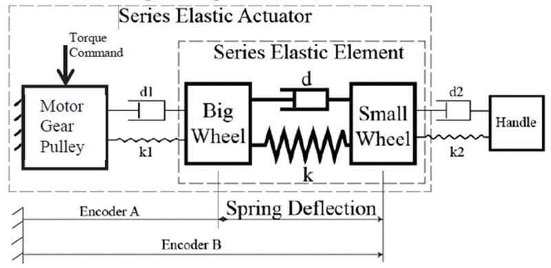
Diagram of physical model of series elastic actuator.
The primary control term was a feedforward term associated with the torque/current constant of the motor and gearing ratio. To reduce errors from model inaccuracy, inertia and friction, we included a PID feedback control term and tuned the gains of each SEA separately using Ziegler-Nichols method [24]. Reference torque signal is the input and is converted into a command spring deflection angle for the feedback term.
We designed and implemented different control modes, including a) free mode, b) wall mode and c) torque control mode (Fig. 5). In free mode, the exoskeleton follows the movement of the user with minimal residual force felt by the user. Reference torque is zero and thus the motors work to keep spring deflection zero. For wall mode, we allow free mode within a certain angular range, and outside the range, the motor regulates spring length so that the user feels resistance to movement similar to hitting a wall of predefined stiffness. For torque control mode, the desired torque profile is converted into a desired spring deflection pattern.
Fig. 5.
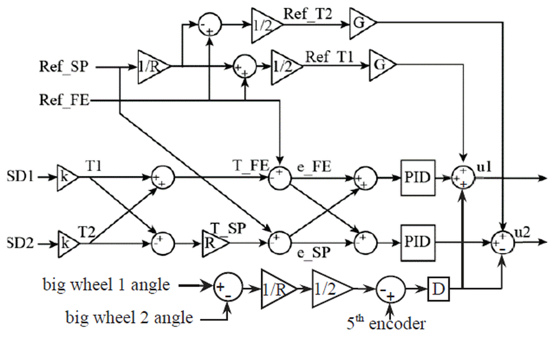
Control diagram illustrating torque control approach. Current spring deflections (SD1 and SD2) are the difference between encoders on each SEA. They are converted to current torque T1 and T2 through the SEE stiffness k, which varies nonlinearly with spring deflection. Flexion-extension torque and supination-pronation torque T_FE and T_SP are calculated according to (1) and (2). Ref_FE and Ref_SP represents reference torque in flexion-extension and supination-pronation. The flexion-extension torque error, e_FE, is feed into both controllers with the same sign so that both SEA can work together to decrease e_FE. The supination-pronation error, e_SP, is fed in to the controllers with opposite sign. At the output stage, control voltages voltage, u1 and u2, are sent to the motor amplifiers.
III. Experimental Method And Results
We conducted benchtop testing and quantified the performance in terms of the stiffness profile estimation, single SEA module bandwidth, flexion/extension and supination pronation step response, torque accuracy bandwidth, impedance in free mode, max wall stiffness and 2-DOF coordination. Bowden cable friction increases as the bend of the cable increases [25]. We set the cable at 90 degrees for testing, which we estimate as the largest angle necessary when this elbow device is integrated into a whole arm exoskeleton.
A. Stiffness Profile Estimate
The stiffness of the SEA was characterized by loading and unloading known loads 10 times and measuring deflection angles [Fig. 6(a)]. This setup contains 6 tension springs with a stiffness of 9.57 N/mm and rest length of 15.75 mm. A theoretical model stiffness was calculated based on the geometry of the SEA, known spring parameters, and assuming the springs pivot around their ends and do not bend. Simplified deformation of SEE is depicted in Fig. 2(b). With a deformation angle of θ, the torque generated by each spring is given by:
| (3) |
With F being spring force, h being effective lever arm, k being spring stiffness, l0 being spring rest length, r and R being SEE inner and outer diameter. Equation (3) describes the SEE’s torque at any given angle, and can be simply treated as the SEE’s theoretical stiffness function.
Fig. 6.
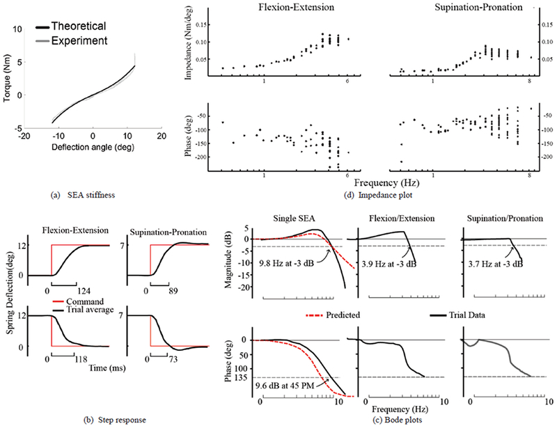
Benchtop test on system dynamics and performance. (a) Series elastic element stiffness. Experimental data vs simulation data. The complete system is composed of 2 of these elastic elements in parallel, so the total system stiffness profile would be the profile depicted scaled by a factor of 2. (b) System step response on F.E. and S.P. (c) System dynamic response bode plots. Single SEA module was measured independently. F.E. and S.P. performance is measured afterward. (d) Experimental data on system impedance in free mode. End-effector was moved by human in different frequency and reactive force and torque is measured with ATI Gamma torque sensor.
Comparison between experimental and theoretical results found a 0.16 Nm RMS error, which is less than 3.3% of applied load. The close correlation between experimental data and theoretical predictions shows we can accurately predict stiffness profiles with different spring set ups in the future without the need to confirm experimentally. The theoretical model predicts the stiffness increases from 0.17 Nm/deg at zero deflection to 0.73 Nm/deg at 12 degrees.
B. FE and SP Step Response
Step response tests were performed for both flexion/extension and supination/pronation with the output of the device rigidly fixed. For flexion/extension, a 8.6 Nm torque step was commanded, with each SEA providing 4.3 Nm torque. For supination/pronation, 6.9 Nm torque was commanded, with each SEA providing 3.45 Nm in torque. The 8.6 Nm step choice for FE was chosen because higher torque steps caused collision of the two wheels of the SEA. The 6.9 Nm choice for SP exceeds the target torque of 5 Nm. Five trials were done for each setup.
Data is presented in Fig. 6(b). For flexion/extension, the 90% rise and fall times were 0.125 ± 0.007 s (mean ± s.d.) and 0.119 ± 0.011 s, with −4.8 % and 5.1 % overshoot, respectively. For supination/pronation, the 90% rise and fall times were 0.089 ± 0.004 s and 0.073 ± 0.002 s, with 7.52 % and 10.95 % overshoot, respectively.
C. SEA Module Bandwidth
Open loop bandwidth tests were done to each SEA independently with 5 trials. Experimental spring deflection data were collected from the open loop system with an input chirp signal and the output side of the SEA grounded. The open loop system can be modeled as a mass spring damper system and the open loop transfer function from spring deflection angle (SD) to command voltage (u) is:
| (4) |
in which Km is motor constant times amplifier gain and SEE stiffness, d is damping ratio and k is spring stiffness and M is the mass of the system, including the reflected inertia from the motor-gear. Using Matlab System Identification Toolbox, with 2 poles and 0 zero, the open loop transfer function, Hestimate was determined. The variance-accounted-for (VAF) factor of this estimation was 77.11%.
The closed loop transfer function with a controller C and feed forward gain G has a transfer function of
| (5) |
With a known controller C (from Ziegler-Nichols method) and feed forward compensation G, the closed loop transfer function is known and thus its dynamic response can be predicted.
The experimental Bode plots for a single SEA are shown in Fig. 6(c). With a desired spring oscillation amplitude of ±6 degree, corresponding to ±1.15 Nm, the SEA’s −3 dB magnitude crossover frequency is 9.8 Hz. The 45 degree phase margin crossover frequency is 9.6 Hz.
D. FE and SP Bandwidth
Both flexion/extension and supination/pronation torque bandwidth was measured. SEA output torque can be estimated by measuring spring deflection angle. However, many factors can result in a different torque applied to the user, such as friction and springiness in the differential transmission. We used an ATI Gamma 6-axis torque sensor (ATI Industrial and Automation, Apex, NC) to measure applied torque in both flexion/extension and supination/pronation. One side of the torque sensor was fixed to a rigid work bench and the other side was bolted to the forearm ring of the exoskeleton. The torque measured by the torque sensor is the torque applied to the user.
A torque chirp signal with frequency from 0.01 to 15 Hz was applied as input. The amplitudes were 5.5 Nm in FE and 5.6 Nm in SP. This corresponded to spring deflection angles of 9 degree for FE and 6 degree for SP. This exceeds the target SP torque of 5Nm. For FE, it was not possible to test at higher target torque levels due to the resonance peak which caused the SEAs to hit their end stops as the chirp signal passed through the resonant frequency of the system. For each setup, 5 trials were collected. For FE, the −3 dB magnitude crossover frequency was 3.94±0.01 Hz; 45° phase margin crossover frequency was not reached. For supination pronation, −3 dB magnitude crossover frequency was 3.68 ± 0.09 Hz and the 45° phase margin crossover frequency was not reached.
A single SEA bandwidth was 9.8 Hz, while FE and SP bandwidth decreased to 3.9 and 3.7 Hz. This was caused by the low stiffness in the differential. We measured the stiffness of the differential and found it to be approximately 0.16 Nm/deg. This low differential stiffness was due to minimal pre-tensioning in the cable. The same cables were used for the series elastic actuator bowden cables and the differential. Differences in the pulley diameters resulted in a decrease in differential stiffness by a factor of .46 compared to the stiffness in the bowden cable-pulley transmission. However, the main cause of the low differential stiffness was that the bowden cables were highly pre-tensioned and the differential cables were minimally pre-tensioned. Therefore, the lack of tension in the differential cables resulted in low stiffness around zero load as slack in the line was taken up before force from the SEA could be felt by the user. We incorporated this additional stiffness into the model, and through simulations (Matlab, Simulink, Mathworks), found that the predicted bandwidth decreases from approximately 10 Hz for a single SEA to 4.5 Hz for output of the differential. This is consistent with the drop in bandwidth observed in the empirical data.
E. Impedance Measurement
In a free mode, the exoskeleton should be able to follow the user’s arm movement with minimal resistance felt by the user. Spring deflection angle is regulated to zero. ATI Mini40 6-axis torque sensor was installed at the base of the handle to measure interaction force and torque between the user and the exoskeleton, while the user moves the robot in sinusoidal patterns at different frequencies. The user only focused on either flexion/extension or supination/pronation movements for any given trial.
An added velocity feedback term was used to increase performance in SP free mode. The 5th encoder at the forearm ring detects SP movement. This signal is differentiated and compared to the velocity of the large wheel of the SEE. This error signal drives the velocity control feedback loop. This control loop parallels the PID controllers for each SEA (Fig. 5). However the PID controller uses the small wheel angle as reference signal, but is less effective because movement of the small wheel is resisted by stiction and stiffness in the SEE. Movement of the 5th encoder is less restrained because of slack in the differential cables. We have also tried to add a proportional controller driven by the 5th encoder signal, but within stability, the term was less effective.
Measured torque T is the output and joint displacement angle θ is the input. Experimental impedance can be expressed as:
| (6) |
Ideally, impedance is small, but will increase with frequency of imposed movement. Theoretically at high frequencies, the impedance will plateau at the inherent stiffness of the SEA, corresponding to the case where the large wheel of the SEA stops rotating and the movement frequency is too high for the controller to follow.
We first measured performance in free mode (0 Nm applied output torque) as the arm is moved in sinusoidal trajectories at different frequencies. Measured torque T for both flexion/extension and supination/pronation remained small at low frequency. As the frequency increased, impedance Z showed some increase but never reached SEA stiffness [Fig. 6(d)]. For flexion/extension, impedance stayed around 0.03 Nm/deg at frequencies less than 1 Hz. Max impedance of 0.12 Nm/deg occurred at 3.5 Hz. Maximum residual torque for all trials was 0.5 Nm. For SP, impedance stayed below 0.02 Nm/deg at frequencies less than 1.6 Hz. Max impedance of 0.09 Nm/deg occurred at 3.1 Hz. Max residual torque over all trials was 0.2 Nm.
We also measured the ability to apply a constant torque during free movement. Testing was similar to the impedance mode testing, except a constant SEA deflection was commanded instead of zero deflection. Fig. 7 shows flexion torque and angle as constant torque was commanded and the handle was moved in a sinusoidal pattern at approximately 1 Hz. There were clear fluctuations in torque that increased in magnitude as the desired torque increased. At a desired flexion torque of 9.86 (corresponding to SEA angular deflection of 9 deg), the RMS angular and torque errors were 0.37 deg and 0.56 Nm, respectively [Fig. 7(a)]. At desired flexion torque of Nm (corresponding to SEA angular deflection of 7 deg), the RMS angular and torque errors were 0.29 deg and 0.27 Nm, respectively [Fig. 7(b)]. Similar data was collected for supination/pronation. When holding a 2.9 Nm supination torque, RMS error was 0.37 deg and 0.46 Nm. When holding a 5.5 Nm supination torque, the angular error was 0.38 deg and the torque error was 0.61 Nm. In both DOF, errors increased as the load increases. Also supination torque errors were higher than flexion torque errors. Both of these trends can be attributed to higher SEA stiffness in supination compared with flexion, and higher effective stiffness as load increases (due to the nonlinear spring property). Note that errors in positioning of the SEA results in torque errors that are proportional to effective stiffness. The fluctuations in applied torque shown in Fig. 7 are due to PID servo errors causing the large wheel of the SEA (encoder A) to lag behind the desired angle setpoint trajectory (encoder B) during these fast oscillations. It was not possible to increase feedback gains to remove these errors.
Fig. 7.
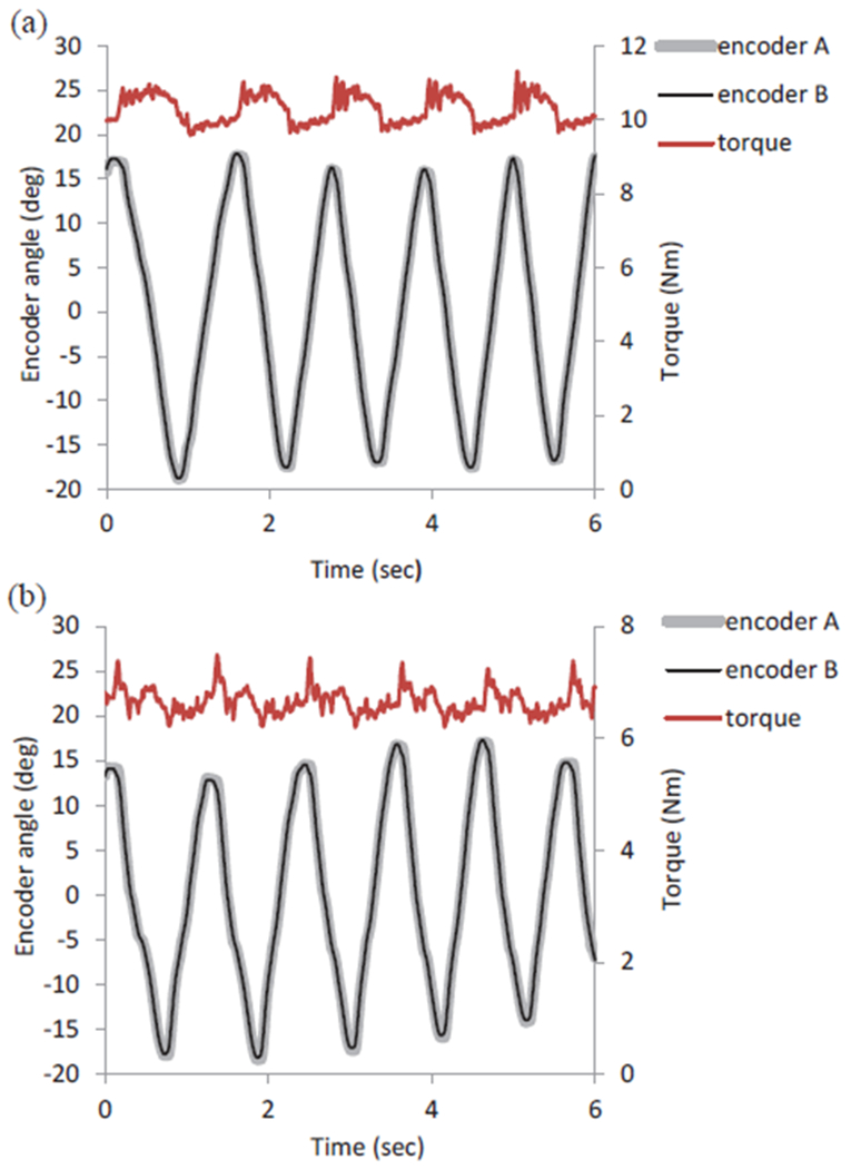
Torque and angle data as (a) 9.86 Nm and (b) 6.5 Nm constant flexion torque was commanded and the handle was moved in a sinusoidal pattern throughout the ROM. To allow visual inspection of servo errors, the targeted SEA deflection corresponding to the target torque level was added to encoder A values, so that encoder A and B profiles would overlay.
F. Wall Mode
Haptic interfaces require simulation of walls or a physical stiffness. The end-effector operates in free mode within a certain range of motion. When exceeding the range, the end-effector should behave as if hitting a rigid wall. The goal of this testing was to determine the maximum possible wall stiffness that can be simulated before instability. The FE wall was set so that below 10 degree, the system runs free mode. Above 10 degree, the system runs wall mode. With an angle of 9 degree into the wall, the measured wall stiffness for flexion/extension reached 0.45 Nm/deg. At a max SEE deflection angle of 12 degree, the theoretical pushback torque is around 9 Nm according to Matlab simulations. When the SEE reaches its max deflection, the two moving parts bottoms out and the SEE behaves like a rigid disc, providing infinite stiffness. According to [20], the max stiffness cannot exceed inherent stiffness while ensuring passivity. Our experimental data is consistent with this statement as shown in Fig. 8. Due to a gear ratio R of 1.78 in the differential, stiffness for SP is higher than FE stiffness by a ratio of R2.
Fig. 8.
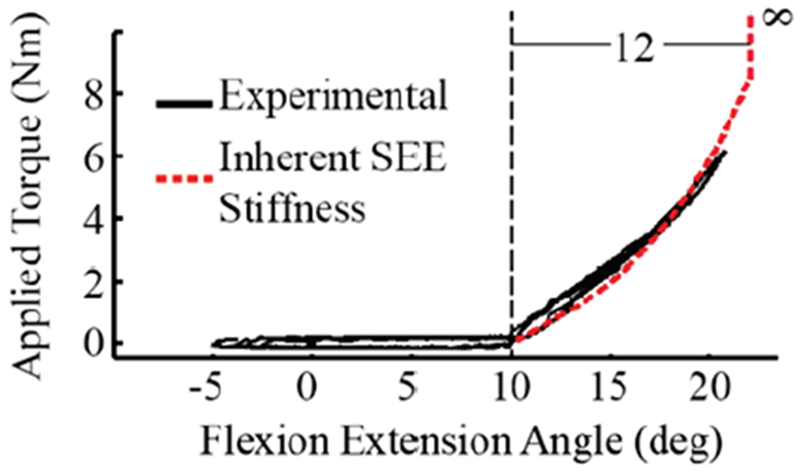
Experimental wall stiffness vs. inherent wall stiffness. Below 10 degree, the system runs free mode. The residual force felt by the subject is around 0.2 Nm or −0.2 Nm. Beyond 10 degree, the interactive force increases, as if hitting into a wall. Inherent stiffness becomes infinite at 12 degrees of spring deflection. The experimental wall stiffness is close to the inherent SEE stiffness. Lower stiffness can be simulated by moving the SEA setpoint to angles >10 deg as the user moves the joint into the wall.
G. Two DOF Coordination
We measured the undesirable coupling between FE and SP by simultaneously applying different command torque profiles to each DOF (Fig. 9). Output torque was measured with the ATI Gamma torque sensor and the forearm ring of the exoskeleton was grounded. FE and SP torques were commanded to the end-effector in the following three scenarios: A) 2 Nm ramp torque on FE and 1.5 Nm sinusoid SP torque [Fig. 9(a)], B) 1 Nm sinusoid FE torque and 2 Nm ramp SP torque [Fig. 9(b)], C) random FE and SP torques [Fig. 9(c)]. In scenario A, the RMS error was 0.08 Nm and 0.15 Nm for FE and SP. In scenario B, RMS error was 0.10 Nm for both DOFs. In scenario C, RMS error was 0.16 Nm for FE and 0.19 Nm for SP.
Fig. 9.
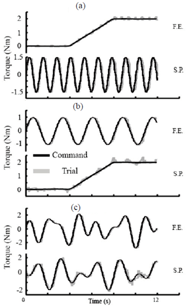
Flexion/extension and supination/pronation coordination. (a) 2 Nm ramp command on F.E. and 1.5 Nm sinusoid command on S.P. (b) 1 Nm sinusoid command on F.E and 2 Nm ramp command on S.P. (c) Random sinusoid torque with max torque of 3 Nm on FE and 2 Nm on SP.
We also measured the coordination of two DOFs in free mode, which is equivalent to setting both commanded torques to zero. The user grabbed the handle and moved randomly and the residual torque was less than 0.5 Nm for FE and 0.4 Nm for SP. RMS error was 0.10 Nm for FE and 0.07 Nm for SP.
The residual torques and joint angle in both DOFs are shown in Fig. 10. Note that angular position and resistance torque are out of phase. This occurs because the residual resistance is always in the opposite direction of movement, so the torque must cross zero as the movement changes direction, which also corresponds to the time points of maximum and minimum angular deflections during oscillatory movements. This is consistent with the large phase shifts shown in the Bode plots in Fig. 6(c), but this is not a negative as long as the peak resistance torque remains small.
Fig. 10.
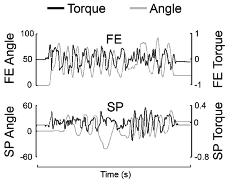
Joint angle and residual torque in free mode. At a moderate speed and range of motion, the user moved the end-effector randomly.
IV. Discussion
The additional gear ratio in SP built in the differential had large implications that should be considered for future designs. Recall that from (1) and (2), there is torque amplification in the SP DOF due to a gear ratio of R=1.78. The designed SP torque capacity is 50% of FE torque. Thus, theoretically a gear ratio of 0.5 would seem more logical, but we chose to use a larger ratio, partly to allow a compact design. A larger gear ratio does provide a larger range of operation.
Based on (1) and (2), the achievable FE and SP torque range has a diamond shape, as shown in Fig. 11. With R=1.78, the operational range is larger when compared to a smaller gear ratio and both SEAs work under smaller output load with the higher gear ratio.
Fig. 11.
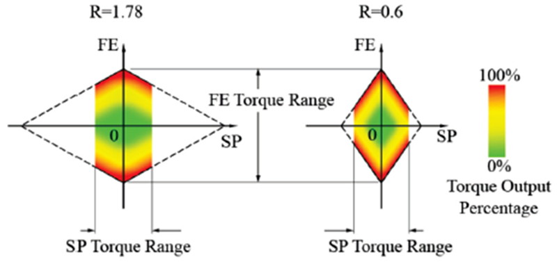
The achievable torque in both FE and SP forms a diamond area, as marked by the dashed line. Each corner of the diamond represents when both SEAs are working at 100% torque output. On each edge of the diamond, one SEA is providing 100% output. During normal operation, max SP torque is designed to be 50% of max FE torque. Therefore, the operation range is smaller, as marked by the colored range. The left figure shows our selection of R=1.78. The right figure shows a smaller gear ratio. Operation area is larger for larger gear ratios.
A downside of choosing this gear ratio for SP is that the physical stiffness in SP is increased by a factor equal to the gear ratio squared. Therefore the SP stiffness is 3.2 times stiffer than FE stiffness. For elbow FE, since there’s no additional gear ratio, the stiffness is given by:
| (7) |
Where K is the stiffness of each series elastic element. Stiffness in forearm SP is given by:
| (8) |
Therefore, errors in positioning of the SEAs are amplified in the SP DOF, and torque errors will be theoretically larger in SP than FE. There is evidence of this in the data in Fig. 9, where SP errors are larger than FE errors.
In general we would like to keep the stiffness low at small SEA deflections to decrease free mode impedance, while maintaining a higher stiffness overall for wall mode, especially for larger deflections. This motivated our choice of an exponential-shaped stiffness profile. We initially used a nearly linear stiffness profiles in the SEE, which resulted in a peak residual torque of 0.3 Nm in free mode testing, as measured by the torque sensor. However, when interacting with the exoskeleton, the human has a much smaller moment arm for SP movement than FE. This 0.3 Nm residual force was still noticeable in free mode. To further decrease residual torque, we implemented the nonlinear spring profile and an additional velocity feedback loop using the added extra encoder to the forearm ring to measure SP rotation directly, instead of indirectly through the SEA encoders. With these modifications, residual torque was decreased to below 0.2 Nm up to 8 Hz.
A single SEA has a bandwidth of 9.6 Hz, limited by the 45 degree phase margin. The motor was operated well under its current limit. The performance is limited by the low stiffness of the SEE and the reflected inertia of the motor and gear. In Fig. 6(c), the bandwidth measured for each DOF using the ATI Gamma torque sensor is less than half of the single SEA’s bandwidth. This can be explained by slack in the cable transmission of the differential. These cables were left minimally pre-tensioned, so their effective springiness was low near zero load, buffering the torque from the SEA, resulting in a lower bandwidth.
Because each SEA produces torque at both FE and SP DOFs simultaneously, independent control of each DOF might be limited by non-zero errors in feedback control. For example, if a constant torque is desired at FE and an oscillatory torque desired at SP, small oscillatory torques will appear in the FE torque as this requires perfectly matched oscillations in the SEA positions that are exactly 180 degrees out of phase. Any errors in these dynamic movements will produce oscillatory errors in the FE constant torque. This is evident in Fig. 9(a) and Fig. 9(b). However, in these cases, the RMS errors were less than 0.15 Nm, indicating the coupling is relatively small. Another form of coupling relates to the stiffness at each DOF (FE and SP). Because of the nonlinear SEA stiffness profile, the instantaneous stiffness (slope of the SEA stiffness profile) depends on the current SEA position. The SEA instantaneous stiffness is higher when the SEA has a large rotation compared to no rotation. Since the SEA position is dependent on both desired FE torque and SP torque, the effective stiffness in FE is dependent on SP commanded torque and vice versa. However, by using an accurate model of SEA stiffness and keeping feedback controller errors small, these coupling errors are kept small (see Fig. 9a and 9b).
Gains in the PID controller were limited by instability, resulting in a conservative position controller. Static friction in the Bowden cables played a significant role. The motors must work to overcome stiction and initiate the movement. At low frequency when the Bowden cable moves slowly, it’s more subject to stiction, especially when SEA deflection changes direction. Therefore, low-frequency performance is compromised to some extent.
Bi-directional Bowden cable transmission has its own pros and cons. One drawback is the maintenance of tension in the cable. Proper tension is necessary to decrease backlash. On the other hand, pretension also introduces friction. Because SEA deflection is measured directly at the SEE, we are less concerned with backlash in the Bowden cable. Lower pretension in the Bowden cable is acceptable to decrease friction, as long as the pretension is enough to ensure a proper winding of the cable. One method to achieve a lower friction and zero backlash is a hydraulic or pneumatic transmission [26]. In terms of friction and stiffness, this method generally performs better than cable transmissions, however maintenance of hydraulic fluid and sealing of lines is a negative. This should be considered for future work.
ULIX has the potential to be a very low mass arm exoskeleton. Our forearm device weighs 0.9kg, while other whole arm robots have masses of 6.8-8 kg [12–14]. However, direct comparison of masses is not possible as it is difficult to predict how the weight of ULIX will increase once the forearm device is extended to include 3DOF of shoulder motion. The cable driven approach used by CAREX has a very low mass of 1.35kg [27]. The ULIX has the advantage of potentially evolving into a lightweight wearable device, which is our ultimate goal, and not possible with the CAREX approach, because of the need for an overhead frame as the anchor points for cables. However, the cable driven approach of CAREX could be adapted to a wearable device if the cables can be routed through the device.
The use of SEA in ULIX effectively reduces the effect of static friction in the actuators and Bowden cables. Residual torque to overcome static friction and initiate movement was less than 0.5 Nm in both DOF. This breakaway torque is significantly higher in robots that rigidly couple the actuators and the joint. For example, the static breakaway torques reported for ARMin III are 0.95 Nm or higher [28].
The combination of a SEA and Bowden cable drive has been studied previously for the LOPES [17] and NEUROExos exoskeletons [21]. They reported torque control bandwidths of 10-11 Hz. Our single SEA bandwidth was similar at 9.6 Hz, but reduced to 3.7-3.9 Hz when measured by a sensor at the end point. Nevertheless, our bandwidth is in line with the 3-4 Hz bandwidth reported by other arm exoskeletons [29, 30]. Bandwidths as high as 35 Hz have been reported for the LIMPACT exoskeleton [31], which also uses SEA, but this required large and expensive hydraulic actuators, which are not compatible with our long term goal of a wearable device.
The LOPES [17] and NEUROExos [21] reported impedance values that increased with frequency of movement up to 0.17 Nm/deg at 4 Hz and 3.2 Hz respectively. The impedance of LIMPACT [12] appears higher, reaching 0.17 Nm/deg at only 2 Hz. Our impedance was less than 0.03 for lower frequencies, increasing to 0.12 Nm/deg at 3.5 Hz for FE and 0.09 Nm/deg at 3.1 Hz for SP. It appears our impedances are lower, but direct comparison is difficult as the testing conditions were slightly different. Furthermore, absolute impedance comparison is not the primary objective of the study. The primary objective is to report performance of a novel non-linear SEA element combined with Bowden cable drive and cable driven differential transmission. We are not aware of another robotic device with this unique combination of elements.
Our low impedance is not due to reduced torque capacity compared with these other robots. The max torque output of LOPES, NEUROExos and LIMPACT are 30 Nm, 15 Nm and 36 Nm, respectively (NEUROExos peak torque is limited by structural strength). The ULIX peak continuous torque (ignoring friction losses) in flexion/extension and supination/pronation is 27.7 Nm and 49.3 Nm, respectively. These torques are reduced to 19.9 Nm and 35.5 Nm after factoring in the efficiency of the gearing. These torque values are much higher than the target peak torques applied to the user (10 Nm and 5 Nm, respectively) because of the need for high torques to accelerate and decelerate the actuator in the face of significant Bowden cable friction and reflected inertia from the gearing. Peak available torque is also reduced when torque combinations are required (Fig. 11). It is also notable that low impedances were achieved in ULIX with potentially portable actuation. We used small motors with a gear reduction of 74/1, whereas LOPES uses very large motors with 8/1 speed reduction, and NEUROExos and LIMPACT use hydraulic actuation.
Similar to our design, the WRES device uses a tendon driven differential transmission for wrist flexion/extension and radial/ulnar deviation [32]. A novel mechanical design places all components on the dorsal side of the hand and provides continuous torque capacity of 1.62 Nm at each DOF. The key difference compared to our device is that we used Bowden cables, which allows actuators to be grounded remotely and not part of the moving mass. This allows for heavier higher torque motors to achieve our target torques of 5 and 10 Nm respectively for our 2 DOFs, with additional torque capacity to handle friction losses and reductions in peak torque when torque combinations are required. Therefore the dynamic performance of these two designs would be expected to be very different.
V. Conclusion
We have described the design of an exoskeleton with series elastic elements and a cable driven differential. The results of benchtop testing provide a detailed characterization of the system dynamics performance. The combination of series elastic elements and cable driven differential resulted in overall satisfying performance. Performance can be further improved with better controller tuning, mechanical design and part selection. The use of exponential-shaped SEE stiffness allowed simulation of an adequate wall stiffness while low stiffness at low SEE angles allowed low impedance values in free mode. Performance overall was adequate for our application of robotic therapy for stroke impaired individuals. More aggressive application, such as for motion augmentation in healthy individuals, are possible if SEE stiffness is increased. Future work includes building a shoulder module with similar features, and integrating a finger exoskeleton [33] to build a whole arm exoskeleton.
Acknowledgments
The research described here was supported by the U.S. Department of Veterans Affairs, Veterans Health Administration, Rehabilitation Research and Development Service (Award number 1I01RX001966-01A1, PI: Peter Lum, Washington DC VAMC). Additional support was provided by the U.S. National Institutes of Health (1R21 HD088783-01, 1R15 HD075166-01A1).
Biographies

Tianyao Chen received a B.S. in Aerospace Engineering from Beihang University in 2011 and an M.S. in Mechanical Engineering from Carnegie Mellon University in 2013. He is working toward his Ph.D. degree in Biomedical Engineering at the Catholic University of America. During his Ph.D. study he also worked as a research assistant at the National Rehabilitation Hospital and as a research associate in Disney Research Pittsburgh. His research interests focus on robotics devices that enhance human motion. He received Best Paper Award in the Medical Devices category at ICRA 2015.

Rafael Casas (SM’18) received a B.S. in Mechanical Engineering in 2010 and M.S. in Mechanical Engineering in 2012 from New Mexico State University. He is a PhD student in Biomedical Engineering at The Catholic University of America and working as a research assistant for Applied Biomechanics and Rehabilitation Research (CABRR) at the National Rehabilitation Hospital. Before working on his PHD, he was awarded the Technical Intramural Research Training Award (IRTA) as part of a three-year fellowship in the Center for Infectious Disease Imaging (CIDI), a joint initiative between Radiology and Imaging Sciences at the NIH Clinical Center and the National Institute of Allergy and Infectious Diseases (NIAID).

Peter S. Lum (M’09) received his B.S. from George Washington University in Mechanical Engineering in 1987. He received the M.S. degree in Applied Mechanics, from the California Institute of Technology, Pasadena CA in 1988. He received the PhD degree in Bioengineering from a joint program between the University of California at San Francisco and Berkley in 1993. He is currently a Professor in the Biomedical Engineering department at The Catholic University of America. He is also a Research Health Scientist at the Washington DC Veterans Affairs Medical Center and the Director of the Center for Applied Biomechanics and Rehabilitation Research (CABRR) at the National Rehabilitation Hospital.
Contributor Information
Tianyao Chen, Biomedical Department of The Catholic University of America, Washington DC 20064.
Rafael Casas, Biomedical Department of The Catholic University of America, Washington DC 20064.
Peter S. Lum, Biomedical Department of The Catholic University of America, Washington DC 20064.
References
- [1].Benjamin EJ, Muntner P, Alonso A, Bittencourt MS, Callaway CW, Carson AP, Chamberlain AM, Chang AR, Cheng S, and Das SR, “Heart Disease and Stroke Statistics—2019 Update: A Report From the American Heart Association,” Circulation. pp. CIR. 0000000000000659, 2018. [DOI] [PubMed] [Google Scholar]
- [2].Gowland C, deBruin H, Basmajian JV, Plews N, and Burcea I, “Agonist and antagonist activity during voluntary upper-limb movement in patients with stroke,” Physical therapy, vol. 72, no. 9, pp. 624–633, 1992. [DOI] [PubMed] [Google Scholar]
- [3].Lum PS, Burgar CG, and Shor PC, “Evidence for strength imbalances as a significant contributor to abnormal synergies in hemiparetic subjects,” Muscle & Nerve: Official Journal of the American Association of Electrodiagnostic Medicine, vol. 27, no. 2, pp. 211–221, 2003. [DOI] [PubMed] [Google Scholar]
- [4].Dewald JP, Pope PS, Given JD, Buchanan TS, and Rymer WZ, “Abnormal muscle coactivation patterns during isometric torque generation at the elbow and shoulder in hemiparetic subjects.” Brain, vol. 118, no. 2, pp. 495–510, 1995. [DOI] [PubMed] [Google Scholar]
- [5].Huang VS, and Krakauer JW, “Robotic neurorehabilitation: a computational motor learning perspective,” Journal of neuroengineering and rehabilitation, vol. 6, no. 1, pp. 5, 2009. [DOI] [PMC free article] [PubMed] [Google Scholar]
- [6].Mehrholz J, Pohl M, Platz T, Kugler J, and Elsner B, “Electromechanical and robot-assisted arm training for improving activities of daily living, arm function, and arm muscle strength after stroke,” Cochrane Database of Systematic Reviews, no. 11, 2015. [DOI] [PMC free article] [PubMed] [Google Scholar]
- [7].Kim B, and Deshpande AD, “An upper-body rehabilitation exoskeleton Harmony with an anatomical shoulder mechanism: Design, modeling, control, and performance evaluation,” The International Journal of Robotics Research, vol. 36, no. 4, pp. 414–435, 2017. [Google Scholar]
- [8].Garrec P, Friconneau J, Measson Y, and Perrot Y, “ABLE, an innovative transparent exoskeleton for the upper-limb,” 2008 IEEE/RSJ International Conference on Intelligent Robots and Systems, Nice, 2008, pp. 1483–1488. [Google Scholar]
- [9].Frisoli A, Salsedo F, Bergamasco M, Rossi B, and Carboncini MC, “A force-feedback exoskeleton for upper-limb rehabilitation in virtual reality,” Applied Bionics and Biomechanics, vol. 6, no. 2, pp. 115–126, 2009. [Google Scholar]
- [10].Krebs HI, Hogan N, Aisen ML, and Volpe BT, “Robot-aided neurorehabilitation,” IEEE transactions on rehabilitation engineering, vol. 6, no. 1, pp. 75–87, 1998. [DOI] [PMC free article] [PubMed] [Google Scholar]
- [11].Nguyen HB, and Lum PS, “Compensation for the intrinsic dynamics of the Inmotion2 robot,” Journal of neuroscience methods, vol. 214, no. 1, pp. 15–20, 2013. [DOI] [PubMed] [Google Scholar]
- [12].Otten A, Voort C, Stienen A, Aarts R, van Asseldonk E, and van der Kooij H, “LIMPACT: A hydraulically powered self-aligning upper limb exoskeleton,” IEEE/ASME transactions on mechatronics, vol. 20, no. 5, pp. 2285–2298, 2015. [Google Scholar]
- [13].Nef T, Guidali M, and Riener R, “ARMin III–arm therapy exoskeleton with an ergonomic shoulder actuation,” Applied Bionics and Biomechanics, vol. 6, no. 2, pp. 127–142, 2009. [Google Scholar]
- [14].Perry JC, Rosen J, and Burns S, “Upper-limb powered exoskeleton design,” IEEE/ASME transactions on mechatronics, vol. 12, no. 4, ppr408–417, 2007. [Google Scholar]
- [15].Plagenhoef S, Evans FG, and Abdelnour T, “Anatomical data for analyzing human motion,” Research quarterly for exercise and sport, vol. 54, no. 2, pp. 169–178, 1983. [Google Scholar]
- [16].Chiaradia D, Xiloyannis M, Antuvan CW, Frisoli A, and Masia L, “Design and embedded control of a soft elbow exosuit.” 2018 IEEE International Conference on Soft Robotics (RoboSoft), Livorno, 2018, pp. 565–571. [Google Scholar]
- [17].Veneman JF, Ekkelenkamp R, Kruidhof R, van der Helm FC, and van der Kooij H, “A series elastic-and bowden-cable-based actuation system for use as torque actuator in exoskeleton-type robots,” The international journal of robotics research, vol. 25, no. 3, pp. 261–281, 2006. [Google Scholar]
- [18].Brokaw EB, Nichols D, Holley RJ, and Lum PS, “Robotic therapy provides a stimulus for upper limb motor recovery after stroke that is complementary to and distinct from conventional therapy,” Neurorehabilitation and neural repair, vol. 28, no. 4, pp. 367–376, 2014. [DOI] [PubMed] [Google Scholar]
- [19].Collins SH, Kim M, Chen T, and Chen T, “An ankle-foot prosthesis emulator with control of plantarflexion and inversion-eversion torque.” 2015 IEEE International Conference on Robotics and Automation (ICRA), Seattle, WA, 2015, pp. 1210–1216. [Google Scholar]
- [20].Vallery H, Veneman J, Van Asseldonk E, Ekkelenkamp R, Buss M, and Van Der Kooij H, “Compliant actuation of rehabilitation robots,” IEEE Robotics & Automation Magazine, vol. 15, no. 3, pp. 60–69, 2008. [Google Scholar]
- [21].Vitiello N, Lenzi T, Roccella S, De Rossi SMM, Cattin E, Giovacchini F, Vecchi F, and Carrozza MC, “NEUROExos: A powered elbow exoskeleton for physical rehabilitation,” IEEE transactions on robotics, vol. 29, no. 1, pp. 220–235, 2012. [Google Scholar]
- [22].Agarwal P, and Deshpande AD, “Series elastic actuators for small-scale robotic applications,” Journal of Mechanisms and Robotics, vol. 9, no. 3, pp. 031016, 2017. [Google Scholar]
- [23].Whitney JP and Hodgins JK, “A passively safe and gravity-counterbalanced anthropomorphic robot arm,” 2014 IEEE International Conference on Robotics and Automation (ICRA), Hong Kong, 2014, pp. 6168–6173. [Google Scholar]
- [24].Ziegler JG, and Nichols NB, “Optimum settings for automatic controllers,” trans. ASME, vol. 64, no. 11, 1942. [Google Scholar]
- [25].Letier P, Schiele A, Avraam M, Horodinca M, and Preumont A, “Bowden cable actuator for torque-feedback in haptic applications,” 2006 Eurohaptics Conference, Paris, 2006, pp. 3–6. [Google Scholar]
- [26].Whitney JP, Chen T, Mars J, and Hodgins JK, “A hybrid hydrostatic transmission and human-safe haptic telepresence robot,” 2016 IEEE International Conference on Robotics and Automation (ICRA), Stockholm, 2016, pp. 690–695. [Google Scholar]
- [27].Mao Y, Jin X, Dutta GG, Scholz JP, and Agrawal SK. “Human movement training with a cable driven ARm EXoskeleton (CAREX),” IEEE Transactions on Neural Systems and Rehabilitation Engineering, vol. 23, no. 1, pp. 84–92, 2014. [DOI] [PubMed] [Google Scholar]
- [28].Nef T, and Lum P, “Improving backdrivability in geared rehabilitation robots,” Medical & biological engineering & computing, vol. 47, no. 4, pp. 441–447, 2009. [DOI] [PubMed] [Google Scholar]
- [29].Wolbrecht ET, Leavitt J, Reinkensmeyer DJ and Bobrow JE, “Control of a Pneumatic Orthosis for Upper Extremity Stroke Rehabilitation,” 2006 International Conference of the IEEE Engineering in Medicine and Biology Society, New York, NY, 2006. pp. 2687–2693. [DOI] [PubMed] [Google Scholar]
- [30].Ragonesi D, Agrawal S, Sample W, and Rahman T, “Series elastic actuator control of a powered exoskeleton,” 2011 Annual International Conference of the IEEE Engineering in Medicine and Biology Society, Boston, MA, 2011, pp. 3515–3518. [DOI] [PubMed] [Google Scholar]
- [31].Stienen AH, Hekman EE, ter Braak H, Aalsma AM, van der Helm FC, and van der Kooij H, “Design of a rotational hydroelastic actuator for a powered exoskeleton for upper limb rehabilitation,” IEEE Transactions on biomedical engineering, vol. 57, no. 3, pp. 728–735, 2009. [DOI] [PubMed] [Google Scholar]
- [32].Buongiorno D, Sotgiu E, Leonardis D, Marcheschi S, Solazzi M, and Frisoli A, “WRES: a novel 3 DoF WRist ExoSkeleton with tendon-driven differential transmission for neuro-rehabilitation and teleoperation,” IEEE Robotics and Automation Letters, vol. 3, no. 3, pp. 2152–2159, 2018. [Google Scholar]
- [33].Chen T, and Lum PS, “Hand rehabilitation after stroke using a wearable, high DOF, spring powered exoskeleton,” 2016 38th Annual International Conference of the IEEE Engineering in Medicine and Biology Society (EMBC), Orlando, FL, 2016, pp. 578–581. [DOI] [PubMed] [Google Scholar]


