Abstract
Background
An ultrasound image tracking algorithm (UITA) was combined with four-dimensional computed tomography (4DCT) to create a real-time tumor motion-conversion model. The real-time position of a lung tumor phantom based on the real-time diaphragm motion trajectories detected by ultrasound imaging in the superior-inferior (SI) and medial-lateral (ML) directions were obtained.
Methods
Three different tumor motion-conversion models were created using a respiratory motion simulation system (RMSS) combined with 4DCT. The tumor tracking error was verified using cone-beam computed tomography (CBCT). The tumor motion-conversion model was produced by using the UITA to monitor the motion trajectories of the diaphragm phantom in the SI direction, and using 4DCT to monitor the motion trajectories of the tumor phantom in the SI and ML directions over the same time period, to obtain parameters for the motion-conversion model such as the tumor center position and the amplitude and phase ratios.
Results
The tumor movement was monitored for 90 s using CBCT to determine the real motion trajectories of the tumor phantom and using ultrasound imaging to simultaneously record the diaphragm movement. The absolute error of the motion trajectories of the real and estimated tumor varied between 0.5 and 2.1 mm in the two directions.
Conclusions
This study has demonstrated the feasibility of using ultrasound imaging to track diaphragmatic motion combined with a 4DCT tumor motion-conversion model to track tumor motion in the SI and ML directions. The proposed method makes tracking a lung tumor feasible in real time, including under different breathing conditions.
Keywords: Cone-beam computed tomography (CBCT), four-dimensional computed tomography (4DCT), ultrasound imaging tracking, respiratory motion, lung tumors, accuracy
Introduction
The movement of organs during radiotherapy often has considerable negative impacts on the clinical diagnosis, the efficacy of radiation therapy, and the extent of radiation exposure. This expansion of the irradiated area results in normal organ tissues around the tumor also receiving radiation doses (1). The most important cause of intrafraction organ motion is respiratory movement, which mainly affects tumors in the thorax and abdomen such as lung, liver, and pancreatic cancers. Respiration produces considerable chest movements, especially in areas close to the diaphragm (2). Liu et al. (3) reported that the displacement of a lung tumor was maximal in the superior-inferior (SI) direction. They found that the 95% maximum displacements of lung tumors in the SI, medial-lateral (ML), and anterior-posterior (AP) directions were 1.34, 0.40, and 0.59 cm, respectively. Various methods can be used to address the problem of internal organ movement, with the most effective for motion compensation being real-time tumor tracking. This allows radiotherapy to be performed while the patient is freely breathing by adjusting the tumor position or the direction of the radiation beam in real time (4).
Real-time tumor tracking methods involve the use of tumor positioning techniques, which can be divided into direct and indirect methods (5). A direct positioning method is based on utilizing a high-resolution imaging system or implanting a location clip on a tumor, such as kilovolt X-ray imaging (6,7) or electromagnetic sensing (Calypso system) (8). Although such methods have very high accuracy, they can result in additional radiation doses or require the implantation of invasive objects, and thus increase the burden on the patient. An indirect positioning method involves determining the motion trajectories of the tumor based on the trajectories of a surrogate target whose motion is strongly correlated with that of the tumor, such as the displacement of the thoracoabdominal surface. Indirect positioning of the thoracic and abdomen surface generally involves using an optical image tracking system to track markers on the skin or analyzing the surface of the entire chest and abdomen for obtaining the external surface motion (9,10). This noninvasive method continuously monitors the motion trajectories of targets throughout the body during the treatment. However, the use of respiratory surrogates to predict the position of a target within the body requires a suitable model for converting the motion between the body surface and the internal organ. Reducing the uncertainty of such a motion-conversion model and the in vivo breathing pattern requires frequent verification (11). Fassi et al. (12) proposed a respiratory motion-conversion model derived using four-dimensional computed tomography (4DCT) and validated using a marker-free surface method to obtain the motion trajectory of the respiratory surrogate. This approach reduces the time required to estimate and validate the external and internal parameters, but it still involves using a motion-conversion model to convert from the body surface to the internal organ, and the internal organs can exhibit baseline shift (13,14). Therefore, various 4DCT parameters of the motion-conversion model must be updated before each medical treatment in order to reduce baseline shift errors.
The baseline shift errors can be reduced by creating a motion-conversion model of the tumor movement in vivo. An ultrasound monitoring system is a good approach for the in vivo monitoring of target motion, since it involves a noninvasive and nonradioactive scanning process that can operate at a high frame rate. Ultrasound image tracking has been applied at many tumor sites, including the prostate (15) and breast (16). However, ultrasound cannot directly scan a tumor located in the lungs, and so such tumors can only be tracked using indirect positioning. The indirect positioning of a tumor requires the selection of a suitable surrogate whose motion is strongly correlated with that of the tumor. The diaphragm is a good surrogate due to its motion being strongly correlated with that of a lung tumor (17,18), and it can also be tracked using ultrasound imaging (19).
The purpose of this study was to develop a method for the indirect positioning of lung tumors based on ultrasound imaging. The study was conducted in collaboration with the Department of Radiation Oncology at Taipei Medical University Hospital, and it combined an ultrasound image tracking algorithm (UITA) (20) and 4DCT technology. The trajectories of the diaphragm and the tumor phantom were monitored separately over the same time period. The tumor center position and the amplitudes and phases of the two measured target displacement signals were compared and used to indirectly derive the tumor motion-conversion model converted from the motion trajectories of the diaphragm phantom movement. In order to validate the proposed tumor motion-conversion model, a respiratory motion simulation system (RMSS) was used to simulate the relative movements of three objects: diaphragm, lung tumor, and abdomen. The RMSS was set up under the kilovolt imaging system of a linear accelerator (the Varian On-Board Imager) to perform experiments for verifying the target tracking error.
This study uses our previously developed UITA and combined with 4DCT for indirect localization of tumors because of the following advantages: (I) monitoring the tumor motion with ultrasound images is non-invasive; targets that are tracked by ultrasound are not limited to the diaphragm. As long as the organ related to the tumor movement can be tracked, and thus, it has a wide range of applications; (II) compared with the surface optical measurement method, the proposed system in this study can directly monitor and track the internal organ movement, and does not have radiation treatment problems caused by the baseline shift of internal organ movement; (III) 4DCT irradiation is a necessary process for patient before radiotherapy, which is used to plan the PTV position for the doctor, and thus, there is no extra treatment process in the proposed method in this study.
Methods
Materials
Experimental phantom
Three experimental phantoms were used in this study: diaphragm, abdomen, and lung phantoms. The design of the lung phantom structure and abdomen comes from the literature (21). In the referenced literature, the reproduction of abdominal motion is driven by a motor. In this study, the changes in physical properties were used to simulate the abdominal breathing movement in a manner that squeezed the ball. The diaphragm phantom is completely self-designed. The diaphragm phantom was constructed by attaching a rubber belt to the inner wall of a bucket, and filling the bucket with agarose and water as the ultrasound transmission medium to simulate the internal tissues of the human body, as shown in Figure 1A. The abdominal phantom was constructed from an acrylic ball filled with air, as shown in Figure 1B. The lung phantom comprised three layers of materials, as shown in Figure 1C: the outermost layer represented the lung outer skin, the middle layer was the lung structure, and the inner core layer simulated the lung tumor. This design of this lung phantom was based on that reported by Kim et al. (21).
Figure 1.
The experimental setup. (A) Photograph of the diaphragm phantom and the setup of the ultrasound probe. (B) Photograph of the ball representing the abdominal phantom. (C) Schematic of the lung phantom (21). The outermost layer “1” was a latex balloon representing the lung outer skin, the middle layer “1-2” was sponge representing the lung structure, and the inner core layer “1-1” was an elastic ball to simulate the lung tumor. The outer shell “2” was constructed of acrylic and filled with water.
RMSS
The RMSS used in this study can simulate the movements of the three different phantoms (the diaphragm, abdomen, and lung), as shown in Figure 2A. The principle of the simulation is to input prerecorded real human breathing signals to the RMSS, and the RMSS induces movement in the SI direction so that the water bucket (with the rubber belt attached inside) placed above the RMSS simulates breathing movement in the SI direction, and this simulated respiration-induced displacement of the diaphragm phantom is measured by the ultrasound probe. The RMSS also drives the push plate of the abdomen component to partially squeeze the ball (abdominal movement). Squeezing the ball results in motion in the AP direction, and 4DCT was used to detect the deformation of the surface of the ball. In addition, the RMSS drives the push plate of the lung component to compress the balloon (lung movement). Compressing the balloon induces deformation in the SI, AP, and ML directions, and 4DCT was used to measure the displacements of the elastic ball (the tumor phantom) inside the balloon in these three directions. The three phantom components exhibit their own trajectories over the same time period. There are two main states, namely inspiration and expiration, as shown in Figure 2B.
Figure 2.
Schematic diagram of the RMSS with the lung tumor phantom and diaphragm phantom. (A) Schematic of the RMSS; (B) schematic of the RMSS assembly of the lung tumor phantom (elastic ball), diaphragm phantom (rubber belt attached inside the bucket), and abdominal phantom (ball). RMSS, respiratory motion simulation system.
Experimental methods
Tumor motion-conversion model
For creating the tumor motion-conversion model, the lung phantom was scanned by 4DCT with simultaneous monitoring using ultrasound imaging. When the motion signal of the diaphragm phantom analyzed by the UITA in the SI direction, the proposed tumor motion-conversion model can automatically generate the instantaneous motion and position signals of the tumor in the SI and ML directions. This model is divided into two steps: (I) converting the diaphragm phantom position to the tumor phantom position in the SI direction {see Eq. [1]} and (II) converting the tumor phantom position in the SI direction to that in the ML direction {see Eq. [2]}. The parameters for the motion-conversion model obtained from the ultrasound images include the baseline position (DB) and the motion amplitude (DA) of the diaphragm phantom, while the baseline position (TB) and motion amplitude (TA) of the tumor phantom are obtained using 4DCT. The following two linear functions are used to convert the tumor phantom motion in the SI direction into the ML direction:
| SItumor = (SIdiaphragm − DB) × TA/DA + TB | [1] |
where SIdiaphragm is the real-time position of the diaphragm phantom in the SI direction as captured in ultrasound imaging and SItumor is the real-time position of the tumor phantom in the SI direction; and
| MLtumor = M × SItumor + b | [2] |
where MLtumor is the real-time position of the tumor phantom in the ML direction, SItumor is the real-time position of the tumor phantom in the SI direction, M is the slope, and b is the offset.
Ultrasound signal processing
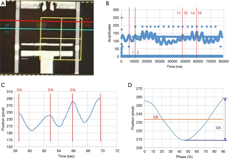
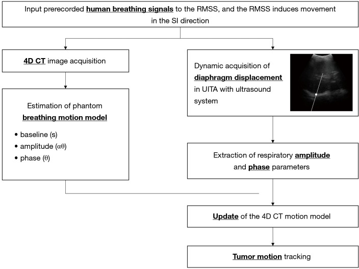
In this study we defined a specific period of time during which the ultrasound signals and 4DCT scanning of the tumor phantom were performed. In 4DCT, the respiratory belt records the amplitude and displacement of the abdominal motion and also the specific time, while computed tomography (CT) was used to scan the position of the tumor phantom, as shown in Figure 3A. The specific time at which CT was used to scan the tumor phantom was determined by the signals recorded using the respiratory belt. The time interval could be identified based on the number of respiratory waves, as shown in Figure 3B. One respiratory wave is defined as the distance from the first peak to the next, and in Figure 3B the respiratory wave number from 12th to 14th is the specific period of time that CT scanned the tumor, usually 2 to 4 respiratory waves. This time interval starts from the just-scanned tumor phantom, which is at the 12th respiratory wave, to the end of the scanned tumor phantom, which is at the 14th respiratory wave. The respiratory wave signals are extracted during this period (usually there are two to four respiratory waves), and each respiratory wave is divided into ten-time phases from 0% to 90%, as shown in Figure 3C. Adding each respiratory wave at the same phase and dividing by the total number of respiratory waves yields an average ultrasound respiratory waveform, as shown in Figure 3D. This figure shows how DB and DA are related to the average ultrasound respiratory waveform. Moreover, Figure 4 shows an overall figure describing the global process of tumor tracking work in this study.
Figure 3.
Ultrasound signal processing correspondence with CT scanning position and signals of the respiratory belt. (A) CT scanning position (blue and red lines) and the corresponding respiration wave numbers in 4DCT: coronal plane, (B) signals of the respiratory belt, (C) respiratory motion signals of the diaphragm phantom captured by ultrasound imaging at the same time as performing CT scans, and (D) average diaphragmatic motion signals. CT, computed tomography; 4DCT, four-dimensional computed tomography.
Figure 4.
Schematic diagram of tumor tracking. RMSS, respiratory motion simulation system; 4DCT, four-dimensional computed tomography.
Validation
Input signals to the RMSS
Four sets of human respiratory signals with individual characteristics and a set of sine waves were extracted from a database containing the respiratory signals of volunteers as captured by a UITA (22). The ultrasound probe was placed on the volunteer’s abdomen while adjusting the brightness and magnification of the ultrasound image so as to maximize image clarity. The UITA was used to capture the real-time motion signal of the volunteer’s diaphragm in the SI direction. The four characteristic patterns of human respiratory signals (22) were as follows: (I) pattern A, normal breathing with yawning; (II) pattern B, baseline shift; (III) pattern C, slow and deep breathing; and (IV) pattern D, rapid breathing. The sine-wave respiratory signal had an amplitude of 20 mm and a frequency of 0.2 Hz.
4DCT signal processing
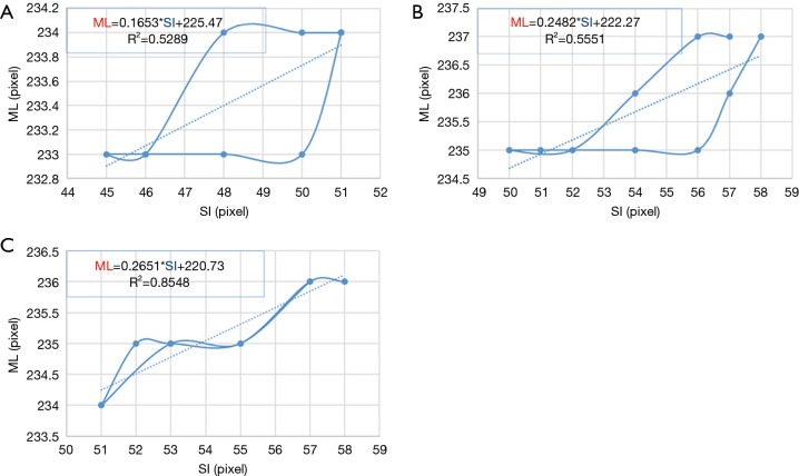
4DCT scanning can generally be used to obtain the three-dimensional motion of the tumor phantom. However, due to the use of verification equipment in this study, cone-beam computed tomography (CBCT) could only be used to perform verification in two dimensions. Thus, only two-dimensional motion signals—in the SI and ML directions—were recorded during this experiment. The motion trajectories of the tumor phantom in the SI direction can provide TB and TA, as shown in Figure 5A. The tumor phantom motion trajectories in the SI and ML directions constructed from the 10 phase trajectories of 4DCT and a linear trend line (dotted line in Figure 5B) was created using the trend-line formula of Microsoft Excel software. This linear formula corresponds to Eq. [2] for the tumor phantom motion in the SI direction converted into the ML direction, as shown in Figure 5B. As indicated in the figure, M in Eq. [2] (the slope) was 0.2651 and b (the offset) was 220.73.
Figure 5.
The tumor phantom motion trajectories in the SI and ML directions. (A) Phase diagram of the tumor phantom for motion trajectories in the SI direction; (B) the motion trajectories of the tumor phantom in the SI and ML directions (the solid line is the motion trajectory of the tumor phantom, and the dotted line is the linear trend line of the motion trajectory). SI, superior-inferior; ML, medial-lateral.
Experimental verification testing
The proposed tumor tracking method was verified using a novel RMSS in two parts. The first part was the creation of a tumor motion-conversion model experiment using a commercial 2D ultrasound imaging system (UF-4000, Fukuda Denshi or BSUS20-32C, Broadsound Corporation) and coupled with a transducer probe (center frequency 3.5 MHz). The parameters of the ultrasound imaging system in this study include the B-mode output pulse, the center frequency of the transducer (convex): 3.5 MHz, gain: 70 db, frame rate: 30 Hz, MI <1.9, and maximum scanning depth: 24 cm. A Philips Brilliance CT Big Bore machine was also used in the verification testing. The tumor motion-conversion model was created by acquiring 4DCT images over the 10 phases, and the motion trajectories of the diaphragm as detected by ultrasound.
The second part of the verification process was the tracking error verification experiment, which mainly involved the ultrasound imaging system and the Elekta Synergy System machine. The motion trajectories of the tumor phantom as observed by CBCT was used as a reference for comparison with the displacement signals of the diaphragm phantom detected by ultrasound imaging and the real-time motion trajectories after conversion through the tumor motion-conversion model. This experiment involved constructing three tumor motion-conversion models representing three patients with lung cancers. Four prerecorded human respiratory signals and one sine-wave respiratory signals were used for each tumor motion-conversion model in the experiment to verify the accuracy of the tracking method under different breathing conditions.
Experimental setup of the tumor motion model
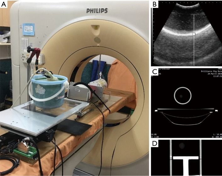
The RMSS and three phantoms were set up on the bed of a Cine-CT machine, the respiratory belt was tied to the ball, and the ultrasound probe was set up on the diaphragm phantom, as shown in Figure 6A. The real-time motion signal of the diaphragm phantom was detected by the ultrasound imaging system, as shown in Figure 6B, and recorded as time-series data. 4DCT was used to scan the area of the lung phantom to generate the original image of the axial section, as shown in Figure 6C. The respiratory belt was used to detect the movement signal of the ball, which was recorded as time-series data. The original 4DCT image corresponds to the time signal of the respiratory belt, which was divided into 10 groups of images obtained at phases 0–90%. These 10 groups of images can be recombined into a composite view of 10 coronal sections by 4DCT, which are the 10 phase diagrams of the tumor movement over a single respiratory cycle, as shown in Figure 6D.
Figure 6.
Experimental setup of the tumor motion model. (A) Photograph of the RMSS and three phantoms mounted on the Cine-CT machine; (B) ultrasound image of the diaphragm phantom; (C) 4DCT axial section; (D) photograph of the tumor position for a phase of 50% under 4DCT. RMSS, respiratory motion simulation system; 4DCT, four-dimensional computed tomography.
Experimental setup of the tracking error verification experiment
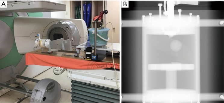
The RMSS and all phantoms were set up on the bed of CBCT, and the ultrasound probe was set up on the diaphragm phantom. The ball was not placed on the RMSS in this experiment since there was not need to use the respiratory belt; the experimental setup was as shown in Figure 7A. The ultrasound imaging system detects the real-time motion of the diaphragm phantom and records it as time-series data, which are then converted into a motion trajectory of the tumor phantom in the SI and ML directions using Eq. [1] and Eq. [2] of the 4DCT tumor motion-conversion model. The verified reference position is the location of the lung tumor phantom obtained by using continuous CBCT irradiation, which generates continuous projection images of the lung tumor phantom position. The CBCT projections will correspond to the time signal irradiated by the CBCT machine, thereby mapping all of the tumor locations during the irradiation. CBCT is only performed in the ML and SI directions, as shown in Figure 7B, and so only the tumor trajectories in these two directions are converted by the ultrasound signal for error verification.
Figure 7.
Experimental setup of the tracking error verification experiment. (A) Photograph of the RMSS and three phantoms mounted in the CBCT machine for error verification experiments; (B) photograph of a lung tumor phantom under CBCT (in the SI and ML directions). SI, superior-inferior; ML, medial-lateral; RMSS, respiratory motion simulation system; CBCT, cone-beam computed tomography.
Results
Tumor motion-conversion model
Figure 8 shows the results of 4DCT for the 10 phases of the motion trajectory map of a tumor phantom and the positional formula for converting the SI position into the ML position. Pearson’s R2 values for the tumor phantom ranged from 0.52 to 0.85, which indicates the correlation between the converted ML value—obtained using the SI-to-ML conversion formula—and the ML value of the tumor phantom motion trajectory.
Figure 8.
Motion trajectories of the 4DCT tumor phantom and the calculated Eq. [2] value for (A) model I, (B) model II, and (C) model III. SI, superior-inferior; ML, medial-lateral; 4DCT, four-dimensional computed tomography.
Tracking error results
Table 1 lists the tracking errors of the three-tumor motion-conversion models under different respiration patterns. There were 500 CBCT irradiations for each experiment, and the measurement time was approximately 90 s. The tracking errors in Table 1 are the absolute errors between the real and estimated tumor trajectories. The median values of the tracking error were 0.59–2.03 mm in the SI direction and 0.48–1.57 mm in the ML direction. The error among all of the tumor motion-conversion models peaked for sine-wave respiration. The median values of the tracking errors for the sine-wave breathing patterns were 2.03 and 0.89 mm in the SI and ML directions, respectively, for model I, 1.93 and 1.29 mm for model II, and 1.32 and 1.57 mm for model III.
Table 1. Absolute tracking errors between the real and estimated tumor trajectories along the ML and SI directions for the three-tumor motion-conversion models under different respiratory patterns [data are median (25–75th percentile) values in millimeters].
| Tumor motion conversion model | Respiratory patterns | Tracking errors (mm) | |
|---|---|---|---|
| SI | ML | ||
| I | Sine | 2.03 (1.05–3.35) | 0.89 (0.46–1.33) |
| I | A | 1.05 (0.49–1.82) | 0.57 (0.28–0.93) |
| I | B | 1.08 (0.44–2.17) | 0.52 (0.25–0.87) |
| I | C | 0.82 (0.45–1.28) | 0.55 (0.34–0.95) |
| I | D | 1.05 (0.42–1.60) | 0.52 (0.28–0.82) |
| II | Sine | 1.93 (0.81–3.56) | 1.29 (0.77–2.44) |
| II | A | 0.94 (0.4–1.75) | 0.66 (0.31–1.2) |
| II | B | 1.70 (0.83–2.68) | 0.90 (0.43–1.50) |
| II | C | 0.59 (0.35–1.01) | 0.75 (0.46–1.62) |
| II | D | 1.26 (0.54–2.15) | 0.66 (0.31–1.02) |
| III | Sine | 1.32 (0.62–2.42) | 1.57 (0.87–2.57) |
| III | A | 0.85 (0.41–1.57) | 0.62 (0.36–1.02) |
| III | B | 1.10 (0.58–1.71) | 1.05 (0.49–1.61) |
| III | C | 0.97 (0.46–1.66) | 0.88 (0.53–1.82) |
| III | D | 0.91 (0.44–1.44) | 0.48 (0.27–0.86) |
SI, superior-inferior; ML, medial-lateral.
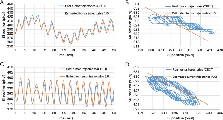
Two kinds of tumor phantom motion tracking trajectories taken from the experimental data as an example are shown in Figure 9. Figure 9A shows the real and estimated tumor phantom tracking trajectories in the SI direction under the respiratory pattern of a baseline shift. Figure 9C shows the real and estimated tumor phantom tracking trajectories in the SI direction under the rapid breathing pattern. It can be seen that good tracking results were also obtained in the case of high-frequency and baseline shift changes of the respiration patterns. Figure 9B,D indicate that the conversion effect of the linear conversion formula {Eq. [2]} compared with the real tumor phantom trajectories has a certain tracking error in the ML direction for the coronal plane.
Figure 9.
Comparison of real tumor phantom trajectories (obtained using CBCT) and estimated tumor phantom trajectories (obtained using ultrasound). (A,B) Motion trajectories of the tumor phantom in the SI direction and all of the recorded motion trajectories of all tumors in the coronal plane, respectively, under respiratory pattern B and tumor motion-conversion model II. (C,D) Motion trajectories of the tumor phantom in the SI direction and all of the recorded motion trajectories of all tumors in the coronal plane, respectively, under respiratory pattern D and tumor motion-conversion model II. Each pixel corresponds to 0.3 mm. SI, superior-inferior; ML, medial-lateral; CBCT, cone-beam computed tomography.
Figure 10 shows the total tracking errors of the three-tumor motion-conversion models under different respiratory patterns, computed as the square root of the sum of the squared errors along the two image dimensions (SI and ML). It can be seen that the tracking errors varied between the different motion-conversion models. For the same respiratory patterns but different tumor motion-conversion models, Model II had the worst tracking error with the exception of respiratory pattern C, and it had the greatest influence on respiratory pattern B. The tracking error was largest for Model II and respiratory pattern B, with a median of 2 mm, while it was smallest for Model I and respiratory pattern B, with a median of 1.3 mm. For the same tumor motion-conversion model, the tracking error was largest for a sine-wave respiratory pattern, and its median value varied between 2.3 and 2.8 mm.
Figure 10.
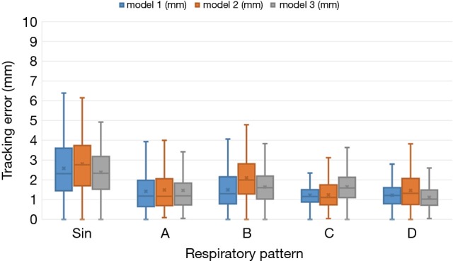
Box-and-whisker plots of the tumor phantom tracking error. Each plot shows the median, first and third quartiles, and range.
To consider all of the effects of respiratory motion on the tracking accuracy of the tumor phantom, Fassi et al. (12) calculated the following error parameters for each complete respiratory cycle during real and estimated tumor phantom trajectories: baseline, amplitude, period, and phase. The present study analyzed the error parameters of the tracking signals in the SI direction for the model II, since this had the worst tracking error, as presented in Table 2. The ranges of the median values of the baseline, amplitude, period, and phase errors were 0.09–0.69 mm, 0.22–1.48 mm, 180–380 ms, and 1.98–12.24%, respectively.
Table 2. Absolute tracking errors along the SI direction between the respiratory variables computed for each breathing cycle identified on the real and estimated tumor motion trajectories in model II [data are median (25–75th percentile) values in millimeters].
| Tumor motion-conversion model | Respiratory pattern | Baseline error, mm | Amplitude error, mm | Period error, ms | Phase error, % |
|---|---|---|---|---|---|
| II | Sine | 0.09 (0.05–0.17) | 0.22 (0.22–0.54) | 190 (180.0–310.0) | 10.04 (4.04–12.81) |
| II | A | 0.57 (0.48–0.64) | 1.30 (1.04–1.59) | 228 (138.0–287.0) | 7.12 (5.18–13.53) |
| II | B | 0.69 (0.55–0.79) | 0.57 (0.25–1.01) | 210 (120.0–270.0) | 8.86 (5.15–12.94) |
| II | C | 0.61 (0.43–0.66) | 0.26 (0.18–0.61) | 380 (311.0–470.0) | 1.98 (0.98–3.15) |
| II | D | 0.52 (0.41–0.61) | 1.48 (1.35–1.58) | 180 (121.0–269.0) | 12.24 (9.25–19.32) |
SI, superior-inferior.
Discussion
Table 1 indicates that the median values of the tracking errors were similar in the SI and ML directions, which is due to the linear conversion performed using Eq. [2] not fully expressing the motion trajectories of the tumor phantom. Figure 8 clearly shows that the motion trajectories of the 4DCT tumor phantom differed from those for the linear Eq. [2]. The data in Figure 8 and Table 1 indicate that the median values of the maximum tracking errors in the ML direction were 1.57, 1.29, and 0.89 mm for Models III, II, and I having the strongest (R2=0.85), second-strongest (R2=0.56), and weakest (R2=0.53) correlations, respectively. These findings indicate that the correlation coefficient (R2) of the tumor motion-conversion model is not directly related to the tracking error in the ML direction. Figure 9A,C show that the tumor phantom tracking in the SI direction has a stronger correlation and higher accuracy even under the conditions of a baseline shift and high-frequency respiratory pattern. In Figure 9B,D the tracking results in the SI direction are good, while a slight tracking error is evident in the ML direction.
The tracking error of each tumor motion-conversion model was analyzed under different respiratory patterns. Figure 10 shows that the tracking error was the worse for Model II and for a sine-wave respiratory pattern. In an attempt to understand the cause of the tracking error, a parameter analysis table of tracking errors was constructed for Model II. Table 2 indicates that Model II had a lower baseline error and amplitude error for sine-wave than for other respiratory patterns, but its overall tracking error was the highest. This is because the phase error has the greatest influence on all of the error parameters. Although the phase error was only 10%, a large amount of movement will result in a large tracking error. The phase error may be related to the respiratory frequency, and it was worst for a sine-wave respiratory signal and rapid respiratory pattern D, while it was acceptable for slow and deep respiratory pattern C. This study found that the phase error had a better effect on the baseline error and was relatively stable. The median value of the baseline shift error was 0.69 mm for respiratory pattern B, which is similar to those for other human respiratory patterns.
The findings of this study were compared with those from traditional X-ray radiotherapy that uses direct tracking techniques. Pepin et al. (23) investigated the CyberKnife® Synchrony® VR respiratory tracking system. The 95% overall errors of the tracking system were measured at 6.9, 4.6, and 3.5 mm in the SI, AP, and ML directions, respectively. Hoogeman et al. (24) measured the accuracy of the CyberKnife® Synchrony® system during real patient treatments, and found correlation errors between external and internal bodies of the system of 1.9, 1.9, and 2.5 mm in the SI, ML, and AP directions, respectively.
The present study also compared its findings with indirect tumor tracking techniques. Fassi et al. (12) reported a tumor tracking method that integrates respiratory motion information provided by 4DCT with surface imaging during treatment, which represents an alternative approach to point-based external and internal correlation models. They found that the ranges of the median values of the tracking errors in the SI and ML directions were 0.7–2.2 and 1.2–2.4 mm, respectively; the corresponding ranges for our indirect tumor motion tracking method were 0.59–2.03 and 0.48–1.57 mm. The tracking errors measured in the present study must take into account the measurement errors of CBCT, whose resolution in the experiments was 0.3 mm/pixel. The error in the respiratory phase may be related to the scanning frequency of CBCT and a projection image being obtained approximately every 180 ms for the CBCT irradiation time.
Many studies have used tumor motion-conversion models constructed using Cine-CT or CBCT data for tumor tracking (25,26). Some studies have proposed adjusting the parameters of the tumor motion-conversion model for each medical plan before radiotherapy in order to obtain updated amplitudes and baseline positions, which improves the tracking accuracy of different lung regions in different patients (12). The tumor motion-conversion model of Fassi et al. converts from the surface optical tracking trajectory into an internal tumor trajectory. Because it is a model of the correlation between external and internal measurements of tumor movement, the baseline changes between the external and internal bodies are very large. The approach applied in the present study could be combined with updating the parameters of the tumor motion-conversion model before each treatment. Furthermore, ultrasound image tracking is a real-time internal organ motion tracking method, and thus has a high positioning accuracy and is not affected by the problem of baseline shift. Future studies could use ultrasound tracking to maintain a high tracking performance without the parameter correction provided by the medical plan. The tumor motion-conversion model proposed in this study involves internal-to-internal motion trajectory, and many studies have used ultrasound imaging to directly track the diaphragm as a surrogate to replace the tracking of a tumor in the lower lobe of the adjacent lung (22,27); however, this approach also requires multiple human clinical trials for verification.
In the future human trial experiments, we might face some difficulties, for example in some patients it may not easy to obtain their ultrasound images of diaphragmatic displacement. The main reason may be due to flatulence, water accumulation or obesity in the patient's body. Therefore, a higher resolution ultrasound imaging system may be needed in the future. In addition, future study must also improve the accuracy of the tumor motion-conversion model in the SI and ML directions.
Conclusions
This study monitored the motion of the diaphragm phantom using ultrasound imaging, and the motion of the tumor phantom was scanned by 4DCT. A tumor motion-conversion model was proposed for real-time tumor tracking method, and the simulation of the lung tumor phantom movement was conducted under CBCT in verification experiments. The experimental results show that the tumor motion-conversion model proposed in this study is feasible for real-time tumor tracking. Ultrasound image tracking is a noninvasive and a direct monitoring method for observing the motion of internal organs. Combining this with a 4DCT tumor motion-conversion model can solve the problem of using ultrasound imaging to track tumor movement in three-dimensional space. The results of this study indicate that tumor tracking in the SI and ML directions produced better tracking results than using a surface optical tracking method. The method applied in this study does not rely on the diaphragm being the tracking target, as long as the surrogate (any organ or tissue) has a stronger correlation with tumor motion, and can be clearly observed using an ultrasound imaging system—these features broaden the applicability of the present method. Future developments could involve combining with a respiratory motion compensation system to reduce radiation damage to the surrounding normal tissues, thereby improving the overall efficacy and safety of radiation therapy.
Acknowledgments
The authors would like to express their appreciation to the Taipei Medical University Hospital, Taiwan for providing the financial and facilities support for this study.
Funding: This work was supported by the National Taipei University of Technology and Taipei Medical University Hospital under Contract USTP-NTUT-TMU-108-03.
Ethical Statement: All procedures performed in studies involving human participants were in accordance with the ethical standards of the institutional and/or national research committee and with the 1964 Helsinki Declaration and its later amendments or comparable ethical standards. Informed consent was obtained from all individual participants included in the study. The ethical approval is approved by the Taipei Medical University Hospital under the reference number: IRB 201501050.
Footnotes
Conflicts of Interest: The authors have no conflicts of interest to declare.
References
- 1.Engelsman M, Damen EM, De Jaeger K, van Ingen KM, Mijnheer BJ. The effect of breathing and set-up errors on the cumulative dose to a lung tumor. Radiother Oncol 2001;60:95-105. 10.1016/S0167-8140(01)00349-8 [DOI] [PubMed] [Google Scholar]
- 2.Giraud P, De Rycke Y, Dubray B, Helfre S, Voican D, Guo L, Rosenwald JC, Keraudy K, Housset M, Touboul E, Cosset JM. Conformal radiotherapy (CRT) planning for lung cancer: analysis of intrathoracic organ motion during extreme phases of breathing. Int J Radiat Oncol Biol Phys 2001;51:1081-92. 10.1016/S0360-3016(01)01766-7 [DOI] [PubMed] [Google Scholar]
- 3.Liu HH, Balter P, Tutt T, Choi B, Zhang J, Wang C, Chi M, Luo D, Pan T, Hunjan S, Starkschall G, Rosen I, Prado K, Liao Z, Chang J, Komaki R, Cox JD, Mohan R, Dong L. Assessing respiration-induced tumor motion and internal target volume using four-dimensional computed tomography for radiotherapy of lung cancer. Int J Radiat Oncol Biol Phys 2007;68:531-40. 10.1016/j.ijrobp.2006.12.066 [DOI] [PubMed] [Google Scholar]
- 4.Schweikard A, Shiomi H, Adler J. Respiration tracking in radiosurgery. Med Phys 2004;31:2738-41. 10.1118/1.1774132 [DOI] [PubMed] [Google Scholar]
- 5.Keall PJ, Mageras GS, Balter JM, Emery RS, Forster KM, Jiang SB, Kapatoes JM, Low DA, Murphy MJ, Murray BR, Ramsey CR, Van Herk MB, Vedam SS, Wong JW, Yorke. The management of respiratory motion in radiation oncology report of AAPM Task Group 76. Med Phys 2006;33:3874-900. 10.1118/1.2349696 [DOI] [PubMed] [Google Scholar]
- 6.Worm ES, Høyer M, Fledelius W, Nielsen JE, Larsen LP, Poulsen PR. On-line use of three-dimensional marker trajectory estimation from cone-beam computed tomography projections for precise setup in radiotherapy for targets with respiratory motion. Int J Radiat Oncol Biol Phys 2012;83:e145-51. 10.1016/j.ijrobp.2011.12.007 [DOI] [PubMed] [Google Scholar]
- 7.Poulsen PR, Cho B, Sawant A, Ruan D, Keall PJ. Dynamic MLC tracking of moving targets with a single kV imager for 3D conformal and IMRT treatments. Acta Oncol 2010;49:1092-100. 10.3109/0284186X.2010.498438 [DOI] [PubMed] [Google Scholar]
- 8.Hansen R, Ravkilde T, Worm ES, Toftegaard J, Grau C, Macek K, Poulsen PR. Electromagnetic guided couch and multileaf collimator tracking on a TrueBeam accelerator. Med Phys 2016;43:2387. 10.1118/1.4946815 [DOI] [PubMed] [Google Scholar]
- 9.Baroni G, Riboldi M, Spadea MF, Tagaste B, Garibaldi C, Orecchia R, Pedotti A. Integration of Enhanced Optical Tracking Techniques and Imaging in IGRT. J Radiat Res 2007;48 Suppl A:A61-74. [DOI] [PubMed]
- 10.Bert C, Metheany KG, Doppke K, Chen GT. A phantom evaluation of a stereo-vision surface imaging system for radiotherapy patient setup. Med Phys 2005;32:2753-62. 10.1118/1.1984263 [DOI] [PubMed] [Google Scholar]
- 11.Seregni M, Pella A, Riboldi M, Orecchia R, Cerveri P, Baroni G. Real-time tumor tracking with an artificial neural networks-based method: a feasibility study. Phys Med 2013;29:48-59. 10.1016/j.ejmp.2011.11.005 [DOI] [PubMed] [Google Scholar]
- 12.Fassi A, Schaerer J, Fernandes M, Riboldi M, Sarrut D, Baroni G. Tumor tracking method based on a deformable 4D CT breathing motion model driven by an external surface surrogate. Int J Radiat Oncol Biol Phys 2014;88:182-8. 10.1016/j.ijrobp.2013.09.026 [DOI] [PubMed] [Google Scholar]
- 13.Neicu T, Berbeco R, Wolfgang J, Jiang SB. Synchronized moving aperture radiation therapy (SMART): improvement of breathing pattern reproducibility using respiratory coaching. Phys Med Biol 2006;51:617-36. 10.1088/0031-9155/51/3/010 [DOI] [PubMed] [Google Scholar]
- 14.Zhao B, Yang Y, Li T, Li X, Heron DE, Huq MS. Statistical analysis of target motion in gated lung stereotactic body radiation therapy. Phys Med Biol 2011;56:1385-95. 10.1088/0031-9155/56/5/011 [DOI] [PubMed] [Google Scholar]
- 15.Serago CF, Buskirk SJ, Igel TC, Gale AA, Serago NE, Earle JD. Comparison of daily megavoltage electronic portal imaging or kilovoltage imaging with marker seeds to ultrasound imaging or skin marks for prostate localization and treatment positioning in patients with prostate cancer. Int J Radiat Oncol Biol Phys 2006;65:1585-92. 10.1016/j.ijrobp.2006.04.019 [DOI] [PubMed] [Google Scholar]
- 16.Warszawski A, Baumann R, Karstens JH. Sonographic guidance for electron boost planning after breast-conserving surgery. J Clin Ultrasound 2004;32:333-7. 10.1002/jcu.20050 [DOI] [PubMed] [Google Scholar]
- 17.Noh DK, Lee JJ, You JH. Diaphragm breathing movement measurement using ultrasound and radiographic imaging: a concurrent validity. Biomed Mater Eng 2014;24:947-52. 10.3233/BME-130889 [DOI] [PubMed] [Google Scholar]
- 18.Cerviño LI, Chao AK, Sandhu A, Jiang SB. The diaphragm as an anatomic surrogate for lung tumor motion. Phys Med Biol 2009;54:3529-41. 10.1088/0031-9155/54/11/017 [DOI] [PubMed] [Google Scholar]
- 19.Harper CJ, Shahgholi L, Cieslak K, Hellyer NJ, Strommen JA, Boon AJ. Variability in diaphragm motion during normal breathing, assessed with B-mode ultrasound. J Orthop Sports Phys Ther 2013;43:927-31. 10.2519/jospt.2013.4931 [DOI] [PMC free article] [PubMed] [Google Scholar]
- 20.Kuo CC, Chuang HC, Teng KT, Hsu HY, Tien DC, Wu CJ, Jeng SC, Chiou JF. An autotuning respiration compensation system based on ultrasound image tracking. J Xray Sci Technol 2016;24:875-892. 10.3233/XST-160598 [DOI] [PubMed] [Google Scholar]
- 21.Kim J, Lee Y, Shin H, Ji S, Park S, Kim J, Jang H, Kang Y. Development of deformable moving lung phantom to simulate respiratory motion in radiotherapy. Med Dosim 2016;41:113-7. 10.1016/j.meddos.2015.10.004 [DOI] [PubMed] [Google Scholar]
- 22.Ting LL, Chuang HC, Liao AH, Kuo CC, Yu HW, Zhou YL, Tien DC, Jeng SC, Chiou JF. Experimental verification of a two-dimensional respiratory motion compensation system with ultrasound tracking technique in radiation therapy. Phys Med 2018;49:11-8. 10.1016/j.ejmp.2018.04.393 [DOI] [PubMed] [Google Scholar]
- 23.Pepin EW, Wu H, Zhang Y, Lord B. Correlation and prediction uncertainties in the cyberknife synchrony respiratory tracking system. Med Phys 2011;38:4036-44. 10.1118/1.3596527 [DOI] [PMC free article] [PubMed] [Google Scholar]
- 24.Hoogeman M, Prévost JB, Nuyttens J, Pöll J, Levendag P, Heijmen B. Clinical accuracy of the respiratory tumor tracking system of the cyberknife: assessment by analysis of log files. Int J Radiat Oncol Biol Phys 2009;74:297-303. 10.1016/j.ijrobp.2008.12.041 [DOI] [PubMed] [Google Scholar]
- 25.McClelland JR, Hughes S, Modat M, Qureshi A, Ahmad S, Landau DB, Ourselin S, Hawkes DJ. Inter-fraction variations in respiratory motion models. Phys Med Biol 2011;56:251-72. 10.1088/0031-9155/56/1/015 [DOI] [PubMed] [Google Scholar]
- 26.Martin J, McClelland J, Yip C, Thomas C, Hartill C, Ahmad S, O'Brien R, Meir I, Landau D, Hawkes D. Building motion models of lung tumours from cone-beam CT for radiotherapy applications. Phys Med Biol 2013;58:1809-22. 10.1088/0031-9155/58/6/1809 [DOI] [PubMed] [Google Scholar]
- 27.Ting LL, Chuang HC, Kuo CC, Jian LA, Huang MY, Liao AH, Tien DC, Jeng SC, Chiou JF. Tracking and compensation of respiration pattern by an automatic compensation system. Med Phys 2017;44:2077-95. 10.1002/mp.12239 [DOI] [PubMed] [Google Scholar]


