Abstract
The current research on acousto-optic effects focuses on the interactions of acoustic waves with static optical properties rather than dynamic features such as tissue blood flow. Diffuse correlation spectroscopy (DCS) is an emerging technology capable of direct measurements of tissue blood flow by probing the movements of red blood cells (RBCs). In this article, we investigated the relations between the acoustic radiation force (ARF) and ultrasonic patterns by the finite element simulations. Based on the outcomes, we experimentally explored how the ultrasound-generated ARF enhance the DCS data as well as the blood flow measurements. The results yield the optimal pattern to generate ARF and elucidate the relations between the ultrasonic emission and flow elevations. The flow modality combing the DCS with ARF modulations, which was proposed in this study for the first time, would promote disease diagnosis and therapeutic assessment in the situation wherein the blood flow contrast between healthy and pathological tissues is insufficient.
1. Introduction
Tissue metabolism is closely associated with the blood oxygen supplies and blood flow. Many diseases alter the tissue metabolic rate, subsequently resulting in abnormal blood flow in microvasculature level [1–3]. Currently, there are a few technologies capable for tissue blood flow measurements. Doppler Ultrasound is a routinely-used technology in clinic for blood flow measurement [4]. However, this technology only probe the flow velocity at large vessel rather than at tissue level. Laser speckle imaging is able to provide the flow imaging [5], but only at superficial level. However, the pathological-induced blood flow changes often occur in deep tissues. Perfusion MRI is an expensive modality generally used for imaging the blood flow in deep brain [6]. However, the high cost and low mobility preclude it from being used routinely for disease screening. In recent years, an emerging technology for tissue blood flow measurement, namely, the diffuse correlation spectroscopy (DCS), has been rapidly developed [2,7–9]. DCS utilizes the temporal autocorrelation of light electric field (i.e., g1(τ)) to quantify the movements of red blood cells (RBCs) within the biological tissues, and it is highly sensitive to the microvasculature blood flow [8,10,11].
DCS for tissue blood flow measurement has been validated by comparison with other flow modalities including Doppler ultrasound, laser Doppler, and perfusion MRI [12–14]. Owing to numerous advantages such as noninvasiveness, portability and low cost, the DCS has been applied on various tissues or organs, including the tumor, brain and skeletal muscles [2,15–17]. The results from numerous studies confirmed the high sensitivity of DCS technology in detecting the tissue blood flow changes.
In some situations, the flow contrast between healthy and pathological tissues may not be so evident, thus restricting the disease diagnosis or therapeutic assessment by use of flow modalities including DCS. The tissue properties or hemodynamics could be manipulated by physical modalities such as ultrasound [18–20]. Particularly, when the light is used to explore these physical parameters, the interaction between the light and ultrasound is called acousto-optic effect [21–23].
Ultrasound is a type of mechanical wave that has smaller scattering effect, leading to deep penetration within the biological tissues. The primary technology utilizing acousto-optic effect is ultrasound modulated optical tomography (UOT), a hybrid technique that adopts the ultrasonic waves to improve the penetration depth and spatial resolution of diffuse optical tomography [19,24,25]. When ultrasound is focused into the tissue, it cause a periodic compression and rarefaction on the tissue, subsequently modulating the local refractive index and displacement of the scatterers. As a result, the imaging of tissue optical properties (e.g., refractive index, scattering coefficient) by the diffused light would be enhanced. Besides modulation of optical property imaging, the ultrasound modulation on temporal autocorrelation of light electric field (i.e., g1(τ)) is also investigated [26,27], e.g., by the technique of ultrasound-tagging light (UTL) [26,28]. The UTL technique investigates the Doppler effect on the diffused light spectrum and reflects the ultrasound characteristics (e.g., frequency) [26,28,29]. Moreover, The UTL technique has been commercialized (e.g., Ornim Medical Inc. [18,29,30]) to measure the blood flow in biological tissues. For this purpose, the temporal cross-correlation between the ultrasound pulse train and the detected light intensity is calculated to obtain a UTL curve, from which a flow index (i.e., CFI) is extracted [18,30]. On the other hand, the acoustic wave generates acoustic radiation force (ARF) that would apply to the moving scatterers (mainly RBCs) within the tissues [19], hence directly manipulating the microvasculature blood flow. Currently, most of UOT studies focus on the modulation of light amplitudes or g1(τ) curves, primarily via manipulating the refractive index and the phase variation of the scatterers [22,31,32]. In fact, the generation of ARF and its impact on the moving scatterers is a complicated process, with various parameters to be adjusted [33]. However, the influence of ARF on tissue blood flow is far less studied.
In contrast to the conventional UOT studies aiming to modulate the optical properties as well as the derived g1(τ) function, in this article, we explored the relations between the ARF and ultrasonic parameters such as amplitude, frequency, as well as types of emission pulse and waveform. Furthermore, we experimentally investigated how the ultrasound-generated ARF affect the g1(τ) function as well as the blood flow measurement. It was found that a few of diseases, such as malignant tumor and inflammation, would promote the cellular density or development of fibrotic tissue, leading to an increase in tissue stiffness [34]. On the other hand, the acoustic radiation force (ARF) could cause movements of small particles within the tissue (e.g., the red blood cells- RBCs), which correlates with the local stiffness of the tissues [35]. Hence, ARF would alter the RBC movements in healthy and pathological tissues in different degree, which can be detected by the DCS blood flow measurement. Those relations would help optimize the ultrasonic parameters, with the aim to enhance the flow contrast between the pathological and healthy tissues, therefore promoting the early diagnosis and therapeutic assessment of various diseases that are associated with hemodynamics and metabolism.
2. Methods
This section starts with an introduction of the DCS instrument and basic principle, followed by the Nth-order linear (NL) algorithm that was recently created by us for blood flow index (BFI) extraction [36,37]. Then, the ultrasound research platform is briefly depicted, followed by the finite element simulation of ultrasonic transmission. The procedures of phantom experiments is finally described.
2.1. DCS principle and instrument
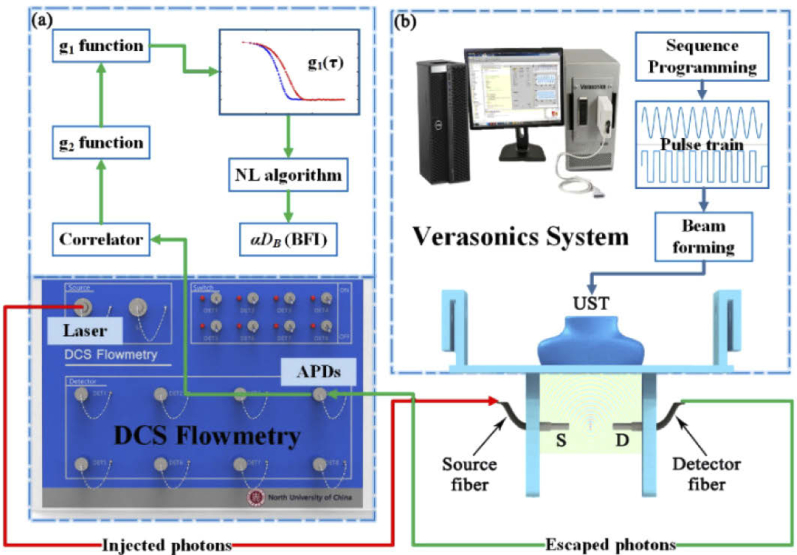
The DCS flowmetry is an instrument used to collect the normalized temporal autocorrelation function of light intensity (i.e., g2(τ)), from which the BFI values are extracted. As shown in Fig. 1(a) , the instrument consists of a near-infrared laser at 785 nm (DL-785-120-SO, Crystalaser Inc., USA), emitting the light at long coherence length (> 5 m) into the tissues via multiple-mode optical fiber. The photons are absorbed or frequently scattered within the tissues, and a portion of photons eventually escape out the tissue and are collected by single-mode detector fiber placed several centimeters away from the source fiber. The collected photons are counted by the single-photon detector (i.e., APDs) and the detector outputs are taken by a digital correlator board. From the APD outputs (i.e., light intensity), the normalized light intensity temporal autocorrelation function (i.e., g2(τ)) is calculated by the digital correlator board. This function is related to the normalized light electric field temporal autocorrelation (g1(τ)) through the Siegert relation [8]. The decay rate of g1(τ) is dependent on the moving of RBCs (i.e., blood flow). For instance, a faster decay in g1(τ) curve indicates a higher blood flow. The value of blood flow can be quantified via the solution of correlation diffusion equation [8,38], due to the fact that the unnormalized g1(τ) function (i.e., G1(τ)) satisfies this type of partial differential equation. Conventionally, by assuming a specific boundary condition (e.g., the semi-infinite boundary condition), the blood flow index (BFI) value is extracted analytically from the diffusion correlation equation [8,38]. In recent years, we have proposed an Nth-order linear (NL) algorithm [36,37], capable of extracting the BFI with higher precision rate by incorporating the geometrical and heterogeneous information of tissues. Section 2.2 illustrate the NL algorithm, which was used to extract the BFI value in this study.
Fig. 1.
(a) The schematic diagram of DCS instrument for blood flow measurement. (b) Optical fiber setup and the Verasonics system for ultrasonic control.
2.2. Nth-linear (NL) algorithm for DCS flow extraction
The details of the NL algorithm were reported elsewhere [37,39]. Briefly, through integrating an Nth-order linear model of autocorrelation function with the Monte Carlo simulation of photon migrations within the tissue, the BFI value can be derived iteratively with the following equations [37,39]:
| (1) |
Where
| (2) |
| (3) |
Here, τ is the delay time of autocorrelation function, k0 is the wave magnitude of the light in the medium, is the reduced scattering coefficient. , which is related to the photon pathlength, can be determined from the Monte Carlo (MC) simulation of photon migrations in the tissue [40], p(s) is the normalized distribution of detected photon path length s. DB is the effective diffusion coefficient and the factor α is added to describe the ratio of “moving” scatterers to the total number of scatterers. In the biological tissues, RBCs (e.g., scatterers) are moving with the blood, so the combined term, αDB, is referred to as BFI.
The term Z · αDB is the slope of linear regression between τ and g1(τ)-1, which is written as:
| (4) |
The slope (Sl) are used to calculate the BFI values by solving the linear equation Eq. (4).
2.3. Verasonics vantage research systems
The Verasonics Vantage Research System (Vantage 64 LE, Verasonics Inc., USA) was used by us to generate the ARF at varied patterns. This system includes the hardware unit and the software (Fig. 1(b)), allowing for transmitting, receiving and processing ultrasonic signals under the control of flexible programming [34]. The Vantage hardware unit consists of one or more Acquisition Boards, and other supporting circuit boards, including the system Backplane (BKP), Transmit Power Controller (TPC), and a UTA Baseboard or ScanHead Interface (SHI) [41]. The UTA connector contains 128 transmitting channels and 64 receiving channels. The Vantage software consists of several application-level software running on MATLAB, the Abstraction Layer (HAL), and other supporting items such as diagnostic tools and hardware device drivers. The Ultrasound Transducer Probe (UST) mode used in this study is L11-5v. The UST contains 128 transmitting elements and 128 receiving elements. Through customer-designed MATLAB script, the Vantage system was controlled to generate different emission modes by adjusting parameters and sequence programming. The optimized ultrasonic parameters will be determined from the acoustic simulation by COMSOL Multiphysics, which is elaborated in Section 2.4.
2.4. Acoustic simulation by COMSOL Multiphysics
The ARF is a nonlinear effect caused by acoustic propagation in liquid, and it is characterized by the acoustic energy density [19]. The acoustic energy density is proportional to the square of the acoustic pressure, which determines the magnitude of the ARF [42]. Since it is difficult to obtain the ARF values via analytical solutions, the finite element method (FEM) is a primary approach to estimate the ARF distributions in a target volume.
The COMSOL Multiphysics is a finite element software containing the acoustic module which enable a broad category of ultrasound simulations in fluids and solids. Most of physical properties associated with the ultrasound transmission, such as scattering, diffraction, emission, radiation, and transmission of sound, are embedded in this module. The acoustic pressure distribution within tissue-mimic medium will be used as criteria to judge the ultrasonic parameters. Those ultrasonic parameters in enhancing the blood flow will be further validated by phantom experiments.
For the acoustic simulations with COMSOL Multiphysics, a complete finite element model, consisting of piezoelectric transducer array, phantom, and perfect match layer (PML), was created. Figure 2 shows the geometrical design of the above components. Specifically, the 64-element UST array was placed on the top of intralipid phantom in rectangle shape. The phantom is bounded by 5 mm thick PML to absorb ultrasound, so as to represent an infinite phantom. Table 1 lists the meshing information of all finite element components. The UST array vibrate to produce ultrasound via the inverse piezoelectric effect.
Fig. 2.
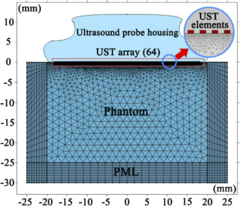
Geometrical model of ultrasound transmission simulation in finite element analysis.
Table 1. Parameter and mesh of geometrical model.
| Domains | Parameter | Expression | Mesh |
|---|---|---|---|
| Transducers | Element Width | 0.27 [mm] | Mapped |
| Element Height | 0.15 [mm] | ||
| Element Spacing | 0.3 [mm] | ||
| Transducers Number | 64 | ||
| Phantom | Intralipid Height | 30 [mm] | Free Triangular |
| Intralipid Width | 50 [mm] | ||
| PML | PML Thickness | 5 [mm] | Mapped |
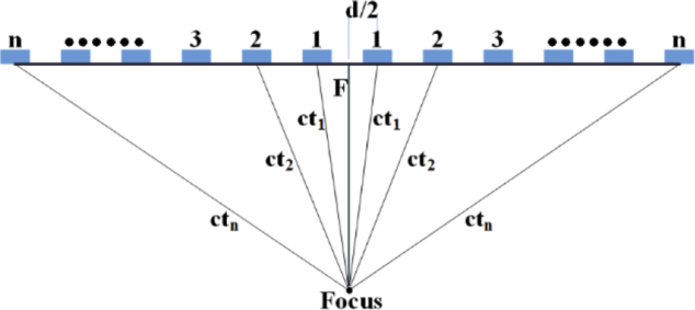
All the UST elements concurrently emit ultrasound pulses at the same frequency and phase, so that the wavefront forms a plane (plane wave). When manipulating the delay time of ultrasound pulse for each UST element, the acoustic wave could focus at a specific location (focus area). Figure 3 depicts the focus and emission delay of the UST elements. By assuming that the focus is located at the central axis, the delay time of the UST elements at symmetrical position are the same. Hence, an index number could denote one pair of UST elements. In Fig. 3, n is the index number of UST elements, d is the distance from the centers of UST elements, c is the speed of sound waves in medium, tn is the delay time corresponding to the nth pair of UST elements, F is the focal depth. As such, the delay time can be derived from the following equations:
| (5) |
Here, N (the maximum of the index number) is the half of the total number of activated UST elements. The speed of sound wave is set as 1.5×10³ m/s in the medium, and the number of UST elements is set as 64, consistent with the setting in Vantage Research System. Table 2 lists the delay time of n pair of UST elements for the focusing depth of 1.0 cm.
Fig. 3.
Diagram of the UST elements for ultrasonic focus and emission delay.
Table 2. Delay time of n pair of UST elements for focusing.
| Index | Delay (s) | Index | Delay (s) | Index | Delay (s) | Index | Delay (s) |
|---|---|---|---|---|---|---|---|
| 1 | 7.0319×10⁻⁶ | 9 | 6.2934e×10−6 | 17 | 4.5494×10⁻⁶ | 25 | 2.2505×10⁻⁶ |
| 2 | 7.0103×10⁻⁶ | 10 | 6.12×10⁻⁶ | 18 | 4.285×10⁻⁶ | 26 | 1.9395×10⁻⁶ |
| 3 | 6.9673×10⁻⁶ | 11 | 5.9318×10⁻⁶ | 19 | 4.0129×10⁻⁶ | 27 | 1.6245×10⁻⁶ |
| 4 | 6.9033×10⁻⁶ | 12 | 5.73×10⁻⁶ | 20 | 3.7337×10⁻⁶ | 28 | 1.3058×10⁻⁶ |
| 5 | 6.8188×10⁻⁶ | 13 | 5.5155×10⁻⁶ | 21 | 3.4481×10⁻⁶ | 29 | 9.8385×10⁻⁷ |
| 6 | 6.7147×10⁻⁶ | 14 | 5.2893×10⁻⁶ | 22 | 3.1565×10⁻⁶ | 30 | 6.5872×10⁻⁷ |
| 7 | 6.5918×10⁻⁶ | 15 | 5.0523×10⁻⁶ | 23 | 2.8594×10⁻⁶ | 31 | 3.307×10⁻⁷ |
| 8 | 6.451×10⁻⁶ | 16 | 4.8054×10⁻⁶ | 24 | 2.5573×10⁻⁶ | 32 | 0 |
2.5. Phantom experiment
The optical properties (absorption and the reduced scattering coefficients) and flow for the phantom experiment are made with the values close to those of human tissues. The detailed procedures for phantom setup are depicted elsewhere [43]. Briefly, the phantom is made up of distilled water, intralipid solution (30% solution, Huarui Inc., China) and 1% India ink solution (Chenguang Inc., China). The India ink and intralipid solution provide the target values of absorption coefficient (0.05 cm−1) and the reduced scattering coefficient (8.0 cm−1), respectively. The intralipid particles also mimic the moving scatterers, i.e., red blood cells (RBCs).
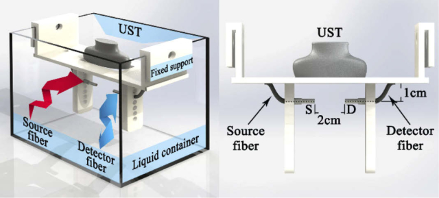
The liquid phantom was contained in a rectangular aquarium (Fig. 4 ). The UST was placed on the top of aquarium and immersed with the liquid phantom. The optical fibers were placed inside the phantom and located at the focus of ARF. A support module was designed to fix the UST and optical fibers in place, allowing the UST to vertically emit the acoustic wave and the optical probe to horizontally measure flow, respectively. The circular holes on both sides of the fixed support permit positioning of the optical fiber at different depths. In the experiment, the distance between the UST and optical fiber axis is set as 1.0 cm, and the distance between source fiber (S) and detector fiber (D) is 2.0 cm.
Fig. 4.
Schematic diagram of phantom apparatus, with illustration of the UST, optical fibers and the fixed support.
Based on the design for the focused ultrasound mode used in this study, the ultrasound power after transducer lens and coupling attenuation is around 5 mW/cm2, which is within safety limit of clinical ultrasound [44].
Figure 5 shows the configuration of the phantom experiments. The ultrasonic platform (Vantage 64 LE) was programed to produce the desired acoustic waves. The ARF generated by acoustic wave manipulates the motions of intralipid particles (mimicking the RBCs), consequently affecting the temporal autocorrelation function of light electric field. From the autocorrelation signals collected by the DCS flowmetry, the BFI value was extracted with the NL algorithm. As such, the influence of ARF on blood flow was quantified and different types of acoustic waves were compared.
Fig. 5.
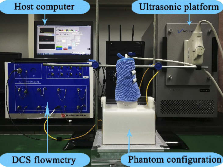
Configuration for phantom experiments.
3. Results
In this section, the ARF distributions derived from finite element simulations at varied ultrasonic patterns were presented. Based on the optimized outcomes, the ARF was applied to the liquid phantom via the Vantage research system and the BFI were longitudinally collected by DCS flowmetry. The BFI values derived from the phantom experiment at varied ultrasonic patterns were used to investigate the ARF impacts on modulation of blood flow. All the computing procedures were performed on a desktop PC (Acer Veriton T830), with 3.4G Hz CPU and 16G memory.
3.1. Results of finite element simulations
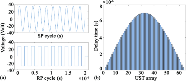
According to the theory of acoustic waves, long pulses tend to generate large ARF. Therefore, we used the voltage function containing ten single pulses to drive the UST. Figure 6(a) shows the voltage function of sine pulse (SP) and rectangular pulse (RP). The pulse frequency, amplitude and the total duration are set as 5 MHz, 36 V, and 2×10⁻⁶ s respectively. Figure 6(b) shows the delay time of ultrasonic focusing for each element of UST array (64 elements in total). The envelope of the delay time is a convex curve, leading to similar shape of wavefront.
Fig. 6.
(a) Voltage function of sine pulse (SP) and rectangular pulse (RP). (b) Delay time of focusing in UST array.
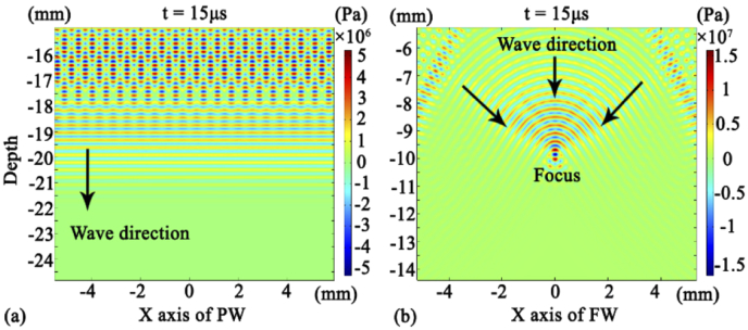
For the same pattern of wave beam, the beam distribution is similar, regardless of the pulse shape (SP or RP). Figure 7(a) exhibits the finite element simulations of plane wave (PW) acoustic distribution at time of 15 µs. The resulting parallel-line shape also represents that of acoustic pressure. Figure 7(b) shows the finite element simulations of focus wave (FW) acoustic distribution at 15 µs. The resulting convex-curve shape also represents that of the acoustic pressure corresponding to this wavefront. With the propagation of the acoustic wave, the wavefront shrinks and ultimately reaches the focal point in parallel. As such, the acoustic wave stack and focus on a depth of 10 mm.
Fig. 7.
(a) Acoustic pressure distribution generated by the PW. (b) Acoustic pressure distribution generated by the FW.
Two types of pulses (sine and rectangular) and two type of waveform (plane and focusing) can form four combinations: sine pulse plane wave (SPPW), rectangular pulse plane wave (RPPW), sine pulse focusing wave (SPFW), rectangular pulse focusing wave (RPFW).
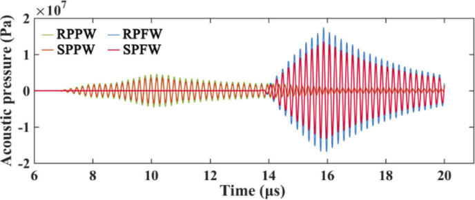
Figure 8 shows the time-course of acoustic pressure at focus area (20 us duration) that was derived from four acoustic combinations. Due to the delay in pulse emission, the received acoustic pressure signal of FW lags behind the PW. The acoustic pressure of different combinations have different magnitudes at the same frequency (5 MHz) and amplitude (36V). The resulting modulus of the peak value are 3.59×10⁶ Pa (SPPW), 4.53×10⁶ Pa (RPPW), 1.36×10⁷ Pa (SPFW), and 1.74×10⁷ Pa (RPFW), respectively. Hence, ARF magnitudes generated by the acoustic combinations are in the following order:
| (6) |
This sequence order will be cross-validated by the phantom experiments reported in Section 3.2.
Fig. 8.
Time-course of acoustic pressure at the focus area, derived from four acoustic combinations (i.e., SPPW, RPPW, SPFW, RPFW).
3.2. Results of phantom experiments
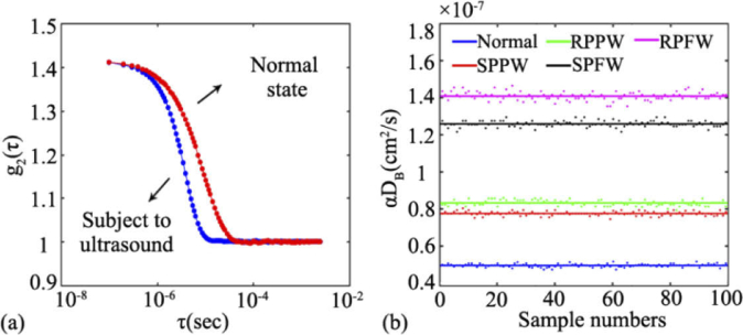
Figure 9(a) shows an example of the normalized light intensity temporal autocorrelation function (i.e., g2(τ) curve) collected from the liquid phantom, with the ultrasound off (in red) and on (in blue). Here, the frequency, amplitude and acoustic wave are set as 5 MHz, 36V and RPPW, respectively. When ultrasound is applied, the decay of the autocorrelation curve remarkably elevates, indicating an increase in the phantom flow.
Fig. 9.
(a) The normalized light intensity temporal autocorrelation function (i.e., g2(τ) curve) collected from the liquid phantom, with the ultrasound off (in red) and on (in blue). (b) The BFI values derived from different combinations of acoustic waves, i.e., normal (without ultrasound), SPPW, RPPW, SPFW, RPFW.
Figure 9(b) shows the time-course of BFI value (100 data points) extracted from the DCS measurements with different acoustic waves being applied. For the purpose of fair comparisons, a constant voltage (36V) is applied to the UST so as to keep the amplitude of the ultrasound unchanged. As is clearly seen, the BFIs with any form of ultrasound are higher than that without ultrasound (the blue line at the bottom), verifying the significant enhancement of ARF on the phantom flow. Among all of the acoustic waves being adopted, the focusing beam improves the BFI to the largest degree. For example, the RPFW and SPFW elevate the BFI value to 2.8 times (pink line) and 2.5 times (black line) respectively, when compared with its baseline (i.e., the BFI without exposure to ultrasound). The plane waves (i.e., rectangular pulse and sine pulse) also substantially elevate the phantom flow (the red line and green line), reaching around 1.5 times of its baseline. Specifically, the average BFIs at the five states are 4.95×10⁻⁸ cm2/s (normal), 7.76×10⁻⁸ cm2/s (SPPW), 8.33×10⁻⁸ cm2/s (RPPW), 1.26×10⁻⁷ cm2/s (SPFW), and 1.41×10⁻⁷ cm2/s (RPFW), respectively. Hence, the BFIs modulated by the ARF are in the following order:
| (7) |
This sequence order is consistent with that of ARF magnitude reported in Section 3.1, confirming that the blood flow is proportionally modulated by the ARF.
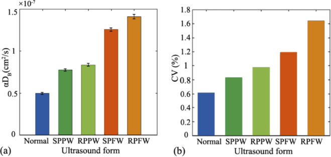
To investigate the flow fluctuation at different acoustic combinations, the mean and standard derivation (mean ± SD) of BFI value over the 100 data points were calculated. As exhibited in Fig. 10(a) , the larger BFI values (e.g., αDB) are associated with larger value of standard derivation. As exhibited in Fig. 10(b), the coefficient of variation (CV, defined as SD/mean) is positively correlated with the mean value of BFI. Nevertheless, all of the BFI variations are small over the measurement period (CV ≤ 2%), indicating that the flow elevation induced by ARF is very stable.
Fig. 10.
At five states (normal, SPPW,RPPW, SPFW, RPFW), (a) the mean and standard derivation (mean ± SD) of BFI value over the 100 data point; (b) The coefficient of variation (CV) of BFI values at five states.
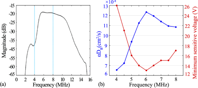
In addition to the amplitude (i.e., Vantage voltage), the ultrasound frequency also impacts the BFI measurements. Figure 11(a) shows ultrasound-induced energy magnitude over the spectrum of 0-16 MHz. It was found that the maximal magnitude appears at around 6 MHz, indicating the highest ultrasonic performance at this frequency. Figure 11(b) exhibits the relation between the BFI values (left Y axis) and the ultrasound frequency (4 to 8MHz), while the voltage is maintained at 32 volts. It was found that the BFI reached the maximum (i.e., 1.24×10⁻⁷ cm2/s) when ultrasound frequency was set at 6 MHz. We also exams the minimal sensitive voltage that could induce the BFI changes, and listed the outcomes in Fig. 11(b) (right Y axis). As anticipated, the 6 MHz requires the minimal voltage value to alter the BFI value, in contrast to other frequency.
Fig. 11.
(a) The spectrum curve of the transducer. (b) The BFI values when subject to acoustic wave at different frequencies.
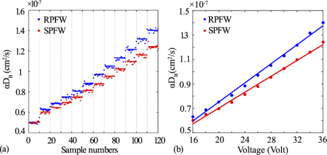
To further exam the amplitude of acoustic wave for enhancing the scatterer movements, we varied the voltage step by step and measured the corresponding BFI values over the entire period. Figure 12 shows BFI measurements with step-increased voltages when two focusing waves (i.e., RPFW and SPFW) were applied. The entire measurement period were divided into 12 steps, and each step contains 10 data points. The first step (initial 10 data points, around 5.02×10⁻⁸ cm2/s) were the normal BFI without subject to ultrasound. The steps 2-12 correspond to the voltage ranges from 16 through 36 volt in 2 volt interval. As clearly seen in Fig. 12(a), the BFI increase gradually with the increase of voltage, and the BFI increment rate with RPFW is larger than those with SPFW. Figure 12(b) shows the linear regression between the voltage and the BFI values. Excellent linear relation were found for both waveforms (r = 0.9970 and 0.9974 for RPFW and SPFW, respectively, p < 0.001).
Fig. 12.
(a) The BFI values when subject to change in ultrasonic voltage step-by-step. (b) Linear regression between BFI and ultrasonic voltages, with correlation coefficient r = 0.9970 and 0.9974 for RPFW and SPFW respectively, p < 0.001.
4. Discussion and conclusions
The Doppler ultrasound is a routinely-used technology in clinic to measure the blood velocity in large vessels, wherein most of the red blood cells (RBCs) move toward a primary direction.However, it is difficult for the Doppler ultrasound toevaluate the blood flow at the microvasculature level because there is no primary direction of RBC movements in capillary network of a bulk tissue. DCS is a relatively new technology emerging in recent years to assess the blood flow at microvasculature level, which is relevant to various diseases such as malignant tumors.
DCS is an emerging technology for tissue blood flow measurement, with advantages of noninvasiveness, portability and low cost. The results from numerous studies confirmed its high sensitivity in detecting the blood flow changes. However, in some cases, the flow contrast induced by tissue pathology may not be so evident. Ultrasound, as a sort of mechanical waves, can be well combined with diffuse optical technology to enhance the detected signals. From the reports on UOT research, ultrasound has been proved to be sensitive in modulating static optical properties such as tissue absorption and scattering. As for the impact on dynamic scatterers (e.g., RBCs), a few theories have been established to elucidate the ultrasonic modulation of the light electric field temporal autocorrelation function (i.e., g1(τ) curve). For example, in some studies wherein low-frequency acoustic waves were applied, the g1(τ) curve was found to reflect the frequency feature of ultrasound. With the established theories, the g1(τ) curve was explained to be modulated by two variables, refractive index of the medium or the phase of the scatterers. On the other hand, the ARF generated by the ultrasound, when being operated at the proper frequency and magnitude, would be strong enough to speed up the RBC movements. However, the influence of ARF on the DCS data (i.e., g1(τ) curve) as well as the subsequent blood flow measurement, is little studied.
ARF is a nonlinear effect caused by the propagation of acoustic wave in a fluid. Due to the ARF, the Brownian motions of the scatterers will be strengthened, subsequently elevating the decay of light autocorrelation function. For the purpose of ultrasonic optimization, two types of pulses (SP and RP) and two type of wave shapes (PW and FW), which represents the most popular ultrasound patterns to generate ARF, were selected by us in this study (Fig. 6 and Fig. 7). The acoustic pressure from a total of four combinations, i.e., SPPW, RPPW, SPFW, RPFW, are quantified by the finite element simulations on a realistic setup of ultrasound measurement (Fig. 2). We found that the focusing wave (FW) performs much better than the plane wave (PW), generating much larger magnitude of ARF (Fig. 8). This finding is reasonable, as the FW is able to concentrate the pressure on the focal area. Additionally, at the same wave shape (FW or PW), the ARF derived from RP has slightly larger magnitude than that derived from the SP. Although the plane wave is not realistic for generating the focus acoustic force, it is frequently used to modulate the light in many UOT studies [45]. Hence, two categories of widely-used ultrasound mode, i.e., plane wave (PW) and focus wave (FW), were adopted as the initial investigation. In next studies, more complicated manipulations of ultrasound (e.g., different apodization modes) will be investigated and optimized for physiological and clinical applications.
With aim to explore the influence of ARF on the flow measurements, a tissue-mimic phantom apparatus was designed (Fig. 4), which allows for both ultrasound emission and optical measurements. Correspondingly, an ultrasonic platform (Vantage 64 LE), which permits precisely controlling the emission of ultrasonic signals, was programed to produce the desired acoustic waves. Moreover, a DCS flowmetry constructed in our laboratory (Fig. 5) was adopted to measure light electric field temporal autocorrelation function (g1(τ) curve) as well as the subsequent flow measurements.
To minimize the influence of ambient noise on optical measurement, in this study, the DCS source and detector fiber were placed inside the liquid phantom. Hence, the ARF enhancement on DCS blood flow measurement would be clearly observed and any other factors will be excluded. For human applications, the optical fibers will be placed on the same side of tissue surface, as did in many clinical studies [1,8,46]. Additionally, we will design a hybrid probe containing both the optical fibers and ultrasound transducer, in order to generate ARF and perform the DCS measurement on the same local tissue. In fact, similar design has been made by other researchers [47], wherein the ultrasound transducer is used to image the target tissue (e.g., tumors), rather than generating the ARF as did in this study.
The results obtained from the phantom experiments illustrate that the ARF would substantially alter the decay of g1(τ) curve and elevate the BFI values (Fig. 9), and the acoustic patterns (pulse and waveform) are critical to change BFI values. As mentioned earlier, ultrasound also affect the g1(τ) curve through Doppler effect (e.g., UTL technique [26,27]), reflecting the acoustic characteristics. We have carefully studied the g1(τ) curve when the ultrasonic wave was applied to liquid phantom. As seen from Fig. 9(a), the decay rate of the g1(τ) curve is substantially elevated when subject to the ultrasound, when compared with the g1(τ) curve at normal state (i.e., without ultrasound). Additionally, the g1(τ) curve completely fits the theoretical model of DCS in which the NL algorithm was used to extract the BFI (αDB). Hence, it is safe to conclude that the change in g1(τ) curve is due to the moving enhancement of scatterers (i.e., BFI) by ARF, rather than other factors. Nevertheless, the blood flow or perfusion measurements by other technologies (e.g., ASL-MRI) will be concurrently conducted in vivo to confirm this observation, which will be the subject of future studies. Among all of the four ultrasound combinations, the pattern of RPFW (i.e., rectangular pulse focusing wave) cause the largest increase in BFI value. Additionally, the order of BFI elevation fully agrees with that of ARF magnitude (Inequality 6 and 7), verifying that the flow is speeded up directly by the ARF, rather than other acousto-optic effects.
We also found that the acoustic waves need to be operated at proper magnitude and frequency so as to manipulate the flow. With the same voltage, the energy magnitude generated by ultrasonic platform varied remarkably at different frequency (Fig. 11(a)). Among these, the 6 MHz was found to be an optimal frequency to manipulate the flow, with the minimal sensitive voltage and the maximal flow enhancement (Fig. 11(b)).
Furthermore, we quantitatively evaluated the modulation of ARF on the flow through varying the voltage of ultrasonic platform step by step (Fig. 12(a)). As anticipated, excellent correlations (p < 0.001) between the voltage and the derived BFI value was found (Fig. 12(b)), regardless of the waveform being adopted. In addition, the FW elevate the flow more rapidly than PW, which is also in agreement with the ARF outcomes obtained from the finite element simulations.
The ARF modulation on the g1(τ) curve as well as the blood flow measurements is fundamentally distinct from the UTL technique mentioned earlier. The UTL technique modulate the optical properties and enforce periodical fluctuations on RBC movements, both of which are reflected from the g1(τ) curve [26,27]. By contrast, we focus on the decay rate of g1(τ) curve in this study, which is primarily dependent on the elevation of RBC movements by ARF. As for the blood flow measurement, the flow index obtained by UTL technique is based on the temporal cross-correlation between the ultrasound pulse train and the detected light intensity (e.g., Ornim Medical Inc. [18,30]), rather than the g1(τ) as used in this study. Additionally, the flow index obtained from UTL technique has arbitrary unit (A.U.), which is different from the unit of effective diffusion coefficient (i.e., cm2/s) used in this study.
In summary, we extensively evaluated the ARF influence on modulation of blood flow in this study. Different types of acoustic pulses and waveform were compared from the finite element simulation outcomes, yielding the optimal pattern to generate ARF. Moreover, the liquid phantom experiments integrating ultrasonic emission and DCS measurements were carried out for the first time. The outcomes elucidate the relations between the ultrasonic emission and its influence on flow elevations via the interactions of ARF. This study would promote the DCS blood flow measurement with combination with ARF modulations. Future research will focus on how to apply this combined technology to various physiological and clinical situations, with aim to improve the disease diagnosis and therapeutic assessment in the situation wherein the blood contrast between healthy and pathological tissues is insufficient.
Funding
National Natural Science Foundation of China10.13039/501100001809 (61671413, 61771433); National Key Research and Development Program of China (2016YFC0101601); National Key Scientific Instrument and Equipment Development Projects of China10.13039/501100012149 (2014YQ24044508); OIT Program of Shanxi Province; Shanxi Scholarship Council of China10.13039/501100003398 (2016-087); Natural Science Foundation of Shanxi Province10.13039/501100004480 (201801D221196); Shanxi postgraduate education innovation program (2019SY433, 2019SY434, 2019SY436).
Disclosures
The authors declare that there are no conflicts of interest related to this article.
References
- 1.Shang Y., Cheng R., Dong L., Ryan S. J., Saha S. P., Yu G., “Cerebral monitoring during carotid endarterectomy using near-infrared diffuse optical spectroscopies and electroencephalogram,” Phys. Med. Biol. 56(10), 3015–3032 (2011). 10.1088/0031-9155/56/10/008 [DOI] [PubMed] [Google Scholar]
- 2.Choe R., Putt M. E., Carlile P. M., Durduran T., Giammarco J. M., Busch D. R., Jung K. W., Czerniecki B. J., Tchou J., Feldman M. D., Mies C., Rosen M. A., Schnall M. D., DeMichele A., Yodh A. G., “Optically Measured Microvascular Blood Flow Contrast of Malignant Breast Tumors,” PLoS One 9(6), e99683 (2014). 10.1371/journal.pone.0099683 [DOI] [PMC free article] [PubMed] [Google Scholar]
- 3.Hou Y., Shang Y., Cheng R., Zhao Y., Qin Y., Kryscio R., Rayapati A., Hayes D., Yu G., “Obstructive sleep apnea-hypopnea results in significant variations in cerebral hemodynamics detected by diffuse optical spectroscopies,” Physiol. Meas. 35(10), 2135–2148 (2014). 10.1088/0967-3334/35/10/2135 [DOI] [PubMed] [Google Scholar]
- 4.Aaslid R., Markwalder T. M., Nornes H., “Noninvasive transcranial Doppler ultrasound recording of flow velocity in basal cerebral arteries,” J. Neurosurg. 57(6), 769–774 (1982). 10.3171/jns.1982.57.6.0769 [DOI] [PubMed] [Google Scholar]
- 5.Stanton A. W., Levick J. R., Mortimer P. S., “Assessment of noninvasive tests of cutaneous vascular control in the forearm using a laser Doppler meter and a Finapres blood pressure monitor,” Clin Auton Res. 5(1), 37–47 (1995). 10.1007/BF01845497 [DOI] [PubMed] [Google Scholar]
- 6.Koretsky A. P., “Early development of arterial spin labeling to measure regional brain blood flow by MRI,” Neuroimage 62(2), 602–607 (2012). 10.1016/j.neuroimage.2012.01.005 [DOI] [PMC free article] [PubMed] [Google Scholar]
- 7.Chung S. H., Feldman M. D., Martinez D., Kim H., Putt M. E., Busch D. R., Tchou J., Czerniecki B. J., Schnall M. D., Rosen M. A., DeMichele A., Yodh A. G., Choe R., “Macroscopic optical physiological parameters correlate with microscopic proliferation and vessel area breast cancer signatures,” Breast Cancer Res. 17(1), 72 (2015). 10.1186/s13058-015-0578-z [DOI] [PMC free article] [PubMed] [Google Scholar]
- 8.Irwin D., Dong L., Shang Y., Cheng R., Kudrimoti M., Stevens S. D., Yu G., “Influences of tissue absorption and scattering on diffuse correlation spectroscopy blood flow measurements,” Biomed. Opt. Express 2(7), 1969–1985 (2011). 10.1364/BOE.2.001969 [DOI] [PMC free article] [PubMed] [Google Scholar]
- 9.Durduran T., Zhou C., Edlow B. L., Yu G., Choe R., Kim M. N., Cucchiara B. L., Putt M. E., Shah Q., Kasner S. E., Greenberg J. H., Yodh A. G., Detre J. A., “Transcranial optical monitoring of cerebrovascular hemodynamics in acute stroke patients,” Opt. Express 17(5), 3884–3902 (2009). 10.1364/OE.17.003884 [DOI] [PMC free article] [PubMed] [Google Scholar]
- 10.Boas D. A., Campbell L. E., Yodh A. G., “Scattering and imaging with diffusing temporal field correlations,” Phys. Rev. Lett. 75(9), 1855–1858 (1995). 10.1103/PhysRevLett.75.1855 [DOI] [PubMed] [Google Scholar]
- 11.Dong L., He L., Lin Y., Shang Y., Yu G., “Simultaneously extracting multiple parameters via fitting one single autocorrelation function curve in diffuse correlation spectroscopy,” IEEE Trans. Biomed. Eng. 60(2), 361–368 (2013). 10.1109/TBME.2012.2226885 [DOI] [PMC free article] [PubMed] [Google Scholar]
- 12.Carp S. A., Dai G. P., Boas D. A., Franceschini M. A., Kim Y. R., “Validation of diffuse correlation spectroscopy measurements of rodent cerebral blood flow with simultaneous arterial spin labeling MRI; towards MRI-optical continuous cerebral metabolic monitoring,” Biomed. Opt. Express 1(2), 553–565 (2010). 10.1364/BOE.1.000553 [DOI] [PMC free article] [PubMed] [Google Scholar]
- 13.Yu G., Floyd T. F., Durduran T., Zhou C., Wang J. J., Detre J. A., Yodh A. G., “Validation of diffuse correlation spectroscopy for muscle blood flow with concurrent arterial spin labeled perfusion MRI,” Opt. Express 15(3), 1064–1075 (2007). 10.1364/OE.15.001064 [DOI] [PubMed] [Google Scholar]
- 14.Zhou C., Eucker S. A., Durduran T., Yu G., Ralston J., Friess S. H., Ichord R. N., Margulies S. S., Yodh A. G., “Diffuse optical monitoring of hemodynamic changes in piglet brain with closed head injury,” J. Biomed. Opt. 14(3), 034015 (2009). 10.1117/1.3146814 [DOI] [PMC free article] [PubMed] [Google Scholar]
- 15.He L., Lin Y., Huang C., Irwin D., Szabunio M. M., Yu G., “Noncontact diffuse correlation tomography of human breast tumor,” J. Biomed. Opt. 20(8), 086003 (2015). 10.1117/1.JBO.20.8.086003 [DOI] [PMC free article] [PubMed] [Google Scholar]
- 16.Dong L., “Diffuse optical measurements of head and neck tumor hemodynamics for early prediction of chemo-radiation therapy outcomes,” PhD dissertation (University of Kentucky, Lexington, Kentucky, USA, 2015). [Google Scholar]
- 17.Sunar U., Quon H., Durduran T., Zhang J., Du J., Zhou C., Yu G., Choe R., Kilger A., Lustig R., Loevner L., Nioka S., Chance B., Yodh A. G., “Noninvasive diffuse optical measurement of blood flow and blood oxygenation for monitoring radiation therapy in patients with head and neck tumors: a pilot study,” J. Biomed. Opt. 11(6), 064021 (2006). 10.1117/1.2397548 [DOI] [PubMed] [Google Scholar]
- 18.Racheli N., Ron A., Metzger Y., Breskin I., Enden G., Balberg M., Shechter R., “Non-Invasive Blood Flow Measurements Using Ultrasound Modulated Diffused Light,” Proc. SPIE 8223, 82232A (2012). 10.1117/12.906342 [DOI] [Google Scholar]
- 19.Li R., Li R., “Ultrasound modulated optical tomography in optical diffuse medium using acoustic radiation force,” (Imperial College London, 2011). [Google Scholar]
- 20.Li R., Elson D. S., Dunsby C., Eckersley R., Tang M.-X., “Effects of acoustic radiation force and shear waves for absorption and stiffness sensing in ultrasound modulated optical tomography,” Opt. Express 19(8), 7299–7311 (2011). 10.1364/OE.19.007299 [DOI] [PubMed] [Google Scholar]
- 21.Sakadzic S., Wang L. H. V., “Correlation transfer and diffusion of ultrasound-modulated multiply scattered light,” Phys. Rev. Lett. 96(16), 163902 (2006). 10.1103/PhysRevLett.96.163902 [DOI] [PubMed] [Google Scholar]
- 22.Wang L. V., “Mechanisms of ultrasonic modulation of multiply scattered coherent light: an analytic model,” Phys. Rev. Lett. 87(4), 043903 (2001). 10.1103/PhysRevLett.87.043903 [DOI] [PubMed] [Google Scholar]
- 23.Zhu L.-L., Li H., “Mechanisms of ultrasonic modulation of multiply scattered incoherent light based on diffusion theory,” Chin. Phys. B 24, 018701 (2015). 10.1088/1674-1056/24/1/018701 [DOI] [Google Scholar]
- 24.Blonigen F. J., Nieva A., DiMarzio C. A., Manneville S., Sui L., Maguluri G., Murray T. W., Roy R. A., “Computations of the acoustically induced phase shifts of optical paths in acoustophotonic imaging with photorefractive-based detection,” Appl. Opt. 44(18), 3735–3746 (2005). 10.1364/AO.44.003735 [DOI] [PubMed] [Google Scholar]
- 25.Elson D. S., Li R., Dunsby C., Eckersley R., Tang M. X., “Ultrasound-mediated optical tomography: a review of current methods,” Interface Focus 1(4), 632–648 (2011). 10.1098/rsfs.2011.0021 [DOI] [PMC free article] [PubMed] [Google Scholar]
- 26.Tsalach A., Shechter R., “Ultrasound modulated light blood flow measurement using intensity autocorrelation function: a Monte-Carlo simulation,” Proc. SPIE 8943, 89433N (2014). 10.1117/12.2037246 [DOI] [Google Scholar]
- 27.Leutz W., Maret G., “Ultrasonic modulation of multiply scattered light,” Phys. B 204(1-4), 14–19 (1995). 10.1016/0921-4526(94)00238-Q [DOI] [Google Scholar]
- 28.Mahan G. D., Engler W. E., Tiemann J. J., Uzgiris E., “Ultrasonic tagging of light: theory,” Proc. Natl. Acad. Sci. U. S. A. 95(24), 14015–14019 (1998). 10.1073/pnas.95.24.14015 [DOI] [PMC free article] [PubMed] [Google Scholar]
- 29.Hori D., Hogue C. W., Shah A., Brown C., Mandal K., “Cerebral Autoregulation Monitoring with Ultrasound-Tagged Near-Infrared Spectroscopy in Cardiac Surgery Patients,” Anesth. Analg. 121(5), 1187–1193 (2015). 10.1213/ANE.0000000000000930 [DOI] [PMC free article] [PubMed] [Google Scholar]
- 30.Oraevsky A. A., Ron A., Racheli N., Breskin I., Metzger Y., Silman Z., Kamar M., Nini A., Shechter R., Balberg M., Wang L. V., “Measuring tissue blood flow using ultrasound modulated diffused light,” Proc. SPIE 8223, 82232J (2012). 10.1117/12.906349 [DOI] [Google Scholar]
- 31.Sakadzic S., Wang L. V., “Modulation of multiply scattered coherent light by ultrasonic pulses: an analytical model,” Phys. Rev. E: Stat., Nonlinear, Soft Matter Phys. 72(3), 036620 (2005). 10.1103/PhysRevE.72.036620 [DOI] [PubMed] [Google Scholar]
- 32.Li J., Ku G., Wang L. V., “Ultrasound-modulated optical tomography of biological tissue by use of contrast of laser speckles,” Appl. Opt. 41(28), 6030–6035 (2002). 10.1364/AO.41.006030 [DOI] [PubMed] [Google Scholar]
- 33.Yao G., Wang L. V., “Theoretical and experimental studies of ultrasound-modulated optical tomography in biological tissue,” Appl. Opt. 39(4), 659–664 (2000). 10.1364/AO.39.000659 [DOI] [PubMed] [Google Scholar]
- 34.Deng Y., Rouze N. C., Palmeri M. L., Nightingale K. R., “Ultrasonic Shear Wave Elasticity Imaging Sequencing and Data Processing Using a Verasonics Research Scanner,” IEEE Trans. Sonics Ultrason. 64(1), 164–176 (2017). 10.1109/TUFFC.2016.2614944 [DOI] [PMC free article] [PubMed] [Google Scholar]
- 35.Meng W., Zhang G. C., Wu C. J., Wu G. Z., Song Y., Lu Z. L., “Preliminary Results of Acoustic Radiation Force Impulse (ARFI) Ultrasound Imaging of Breast Lesions,” Ultrasound Med Biol. 37(9), 1436–1443 (2011). 10.1016/j.ultrasmedbio.2011.05.022 [DOI] [PubMed] [Google Scholar]
- 36.Shang Y., Li T., Chen L., Lin Y., Toborek M., Yu G., “Extraction of diffuse correlation spectroscopy flow index by integration of Nth-order linear model with Monte Carlo simulation,” Appl. Phys. Lett. 104(19), 193703 (2014). 10.1063/1.4876216 [DOI] [PMC free article] [PubMed] [Google Scholar]
- 37.Shang Y., Yu G., “A Nth-order linear algorithm for extracting diffuse correlation spectroscopy blood flow indices in heterogeneous tissues,” Appl. Phys. Lett. 105(13), 133702 (2014). 10.1063/1.4896992 [DOI] [PMC free article] [PubMed] [Google Scholar]
- 38.Lin Y., Huang C., Irwin D., He L., Shang Y., Yu G., “Three-dimensional flow contrast imaging of deep tissue using noncontact diffuse correlation tomography,” Appl. Phys. Lett. 104(12), 121103 (2014). 10.1063/1.4869469 [DOI] [PMC free article] [PubMed] [Google Scholar]
- 39.Zhang P., Gui Z., Guo G., Shang Y., “Approaches to denoise the diffuse optical signals for tissue blood flow measurement,” Biomed. Opt. Express 9(12), 6170–6185 (2018). 10.1364/BOE.9.006170 [DOI] [PMC free article] [PubMed] [Google Scholar]
- 40.Li T., Gong H., Luo Q. M., “Mcvm: Monte Carlo Modeling of Photon Migration in Voxelized Media,” J. Innovative Opt. Health Sci. 03(02), 91–102 (2010). 10.1142/S1793545810000927 [DOI] [Google Scholar]
- 41.Kaczkowski P. J., Daigle R. E., “The Verasonics ultrasound system as a pedagogic tool in teaching wave propagation, scattering, beamforming, and signal processing concepts in physics and engineering,” J. Acoust. Soc. Am. 129(4), 2648 (2011). 10.1121/1.3588831 [DOI] [Google Scholar]
- 42.Torr G. R., “The acoustic radiation force,” Am. J. Phys. 52(5), 402–408 (1984). 10.1119/1.13625 [DOI] [Google Scholar]
- 43.Li T., Lin Y., Shang Y., He L., Huang C., Szabunio M., Yu G., “Simultaneous measurement of deep tissue blood flow and oxygenation using noncontact diffuse correlation spectroscopy flow-oximeter,” Sci. Rep. 3(1), 1358 (2013). 10.1038/srep01358 [DOI] [PMC free article] [PubMed] [Google Scholar]
- 44.Ziedonis A. J. G., “Ultrasonic Power Levels Used In Commercial Equipment For Medical Applications, And How To Control It For Patient's Safety,” Proc. SPIE 0047, 110–111 (1975). 10.1117/12.954035 [DOI] [Google Scholar]
- 45.Gunther J., Andersson-Engels S., “Review of current methods of acousto-optical tomography for biomedical applications,” Front. Guided Wave Opt. Optoelectron. 10(3), 211–238 (2017). 10.1007/s12200-017-0718-4 [DOI] [Google Scholar]
- 46.Shang Y., Zhao Y., Cheng R., Dong L., Irwin D., Yu G., “Portable optical tissue flow oximeter based on diffuse correlation spectroscopy,” Opt. Lett. 34(22), 3556–3558 (2009). 10.1364/OL.34.003556 [DOI] [PubMed] [Google Scholar]
- 47.Xu Y., Zhu Q., “Estimation and imaging of breast lesions using a two-layer tissue structure by ultrasound-guided optical tomography,” J. Biomed. Opt. 20(6), 066002 (2015). 10.1117/1.JBO.20.6.066002 [DOI] [PMC free article] [PubMed] [Google Scholar]


