Abstract
We demonstrate the use of two-color digital holographic microscopy (DHM) for imaging microbiological subjects. The use of two wavelengths significantly reduces artifacts present in the reconstructed data, allowing us to image weakly-scattering objects in close proximity to strongly-scattering objects. We demonstrate this by reconstructing the shape of the flagellum of a unicellular eukaryotic parasite Leishmania mexicana in close proximity to a more strongly-scattering cell body. Our approach also yields a reduction of approximately one third in the axial position uncertainty when tracking the motion of swimming cells at low magnification, which we demonstrate with a sample of Escherichia coli bacteria mixed with polystyrene beads. The two-wavelength system that we describe introduces minimal additional complexity into the optical system, and provides significant benefits.
1. Introduction
Digital holography [1, 2] has found a rich variety of applications in microscopy [3, 4], particularly in microbiology, where it allows fast three-dimensional imaging at spatial resolutions close to the diffraction limit. The morphology and behavior of subjects such as marine diatoms [5,6], sperm and blood cells [7–12], as well as other single-celled eukaryotes [13–18] and bacteria [19–25] have been examined, revealing the refractive index, structure and swimming patterns of these microorganisms. Digital holographic microscopy (DHM) has important advantages over comparable techniques such as confocal microscopy due to the very rapid frame rates that are possible (limited only by the speed of the camera), and by the extended depth of field that holography allows, which is ultimately limited by the coherence length of the light source and the specifications of the image sensor [4]. The performance of the latter is principally governed by the number of pixels and the physical pixel size, although for weakly-scattering subjects, the sensitivity of the camera and various sources of noise can become dominant. Readout noise in the detector electronics, and ultimately photon shot noise [26], provide fundamental limits on the signal-to-noise ratio (SNR) in DHM. Cooling CCD or CMOS detectors can go some way towards alleviating electronic noise sources: many modern cameras optimized for collecting weak signals from fluorescently-labeled biological specimens are equipped with this feature. The drawback of such devices is that sensitivity is typically achieved at the expense of speed, although frame rates of 100 Hz or greater at resolutions greater than one megapixel are now fairly standard. Photon shot noise is due to the statistical fluctuations in the number of photons detected, and results in an SNR that scales as where N is the number of photons collected. A typical way to overcome photon shot noise is simply to increase the illumination level, although this is problematic in biological studies where high incident intensity can damage cells, or cause a change in behavior, particularly when short wavelengths are used [22].
Once a holographic image has been acquired, it can be treated in a number of different ways in order to extract useful information about a sample. Several authors [7, 27, 28] have used DHM as a tool to provide quantitative phase images, providing a map of a sample’s refractive index and inferring (for example) the height of structures along the optical axis. The use of dual wavelengths in the specific case of quantitative phase imaging has been shown to increase the vertical measurement range without phase ambiguity [29–31]. Here, we focus on a fundamentally different use of two-color DHM: imaging the position, orientation and shape of an object within a sample volume. Information can be extracted from holographic data either by fitting the images using known solutions to Maxwell’s equations, e.g. Mie scattering solutions for scattering by spheres [32, 33], or by a model-free approach such as Rayleigh-Sommerfeld back-propagation [34]. The latter is ‘model-free’ in the sense that it makes no a priori assumptions about the shape of the object being imaged. Instead, this reconstruction method models each pixel in the original image as a point source of waves, and computes the structure of the resulting optical field at some distance from the original image [2, 5, 34].
Multiple LEDs have been used in a tilted in-line configuration to image single bacterial cells in a previous study [35]. There, the authors used the tilted illumination to provide different holographic projections of objects even when they were closely spaced in the axial direction. The advantages of this elegant approach were demonstrated in a follow-up work exploring wall entrapment of swimming bacteria [25]. Our study differs from previous work in two important ways. Firstly, in terms of apparatus, our approach removes the need for a colour imaging sensor and simplifies the optical alignment through the use of a wavelength division multiplexer (WDM). Secondly, our feature extraction approach allows us to image extended, flexible objects in three dimensions, even in close proximity to more strongly scattering objects.
In a typical DHM experiment, the optical field is reconstructed at a number of distances from the original focal plane, yielding a stack of images. The final challenge from an optical point of view is to extract useful information from the resulting series of two-dimensional slices through the reconstructed field. A range of object localization strategies have been suggested for DHM, including those based on ‘autofocusing’ techniques. These determine an object’s location along the optical axis, by maximizing image sharpness in terms of spatial frequencies, local gradients or curvature [36, 37]. We use a method based on maximizing the local axial intensity gradient, which has proved useful for faithfully reconstructing extended objects in three dimensions [17]. This approach has limitations in that the processing stages can introduce artifacts close to the object of interest that complicate feature extraction (see results section). The problem is less important in situations where the object of interest has approximately homogeneous refractive index, but more challenging in situations where scatterers of different strengths are placed in close proximity. In this paper, we demonstrate how a two-color DHM setup can be used to tackle this issue when imaging the single-celled microorganism Leishmania mexicana. This species is a pathogen that is transmitted by sandfly bites. The cells are motile, and swim with the aid of a narrow, whip-like organelle known as a flagellum at the leading end of the more substantial cell body. The flagellum is of order 10 μm in length when a cell is motile, but this varies significantly over the course of the life cycle, which also includes non-motile stages [38]. The diameter of the flagellum varies much less, and is roughly 400 nm [39] during motile stages. It beats in a roughly sinusoidal fashion, pulling the cell through the surrounding medium. The flagellum is known to be important for lifecycle progression, providing a tempting target for novel therapies [40].
2. Experimental setup
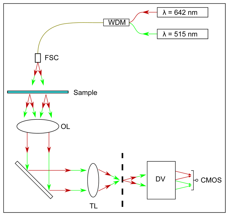
Figure 1 shows the schematic layout of our two-color DHM setup. The illumination was provided by two fiber-coupled diode lasers with wavelengths λgreen = 515 nm and λred = 642 nm. These wavelengths were chosen such that they are within the visible range, for ease of alignment and manipulation with standard optical components; and not integer multiples of each other, which could cause the reinforcement of undesirable artifacts in the images. A WDM was used to couple the output of the lasers into a single fiber, ensuring that the illumination path was the same for both wavelengths. The system was implemented on an inverted Nikon Ti microscope, removing the standard (dry) condenser lens and replacing it with a custom holder compatible with ‘cage-mount’ optical components. The fiber carrying the laser illumination was held in the cage-mount system and directed down onto the sample from a distance of approximately 10 cm. Illuminating from this distance allowed the central, dominant fiber mode to significantly overfill the microscope’s field of view, leading to an approximately uniform intensity in the image plane. In this work, we used two objective lenses: a 20× lens (air, NA 0.50) for imaging and tracking a mixture of Escherichia coli cells and polystyrene beads; and a 60× lens (oil immersion, NA 1.40) for imaging the flagellum of L. mexicana cells. A tube lens offering unit magnification was used to focus the image onto a camera.
Fig. 1.
Optical layout for our simplified dual wavelength setup. A wavelength division multiplexer (WDM) is used to couple the two illumination wavelengths into a single fiber, which is directed onto a free-space coupler (FSC). An objective lens (OL) and tube lens (TL) produce an image of the sample at the microscope image plane, indicated as a vertical dashed line. The DualView apparatus (DV) images this plane with unit magnification onto a CMOS camera, spatially separating images created by the two illumination sources (see text).
A ‘DualView2’ two-channel imaging system with unit magnification (Photometrics DV2 model) was used to laterally separate the images formed by the different wavelengths on a single (monochrome) CMOS sensor. The critical component in our DualView2 unit was a long-pass dichroic mirror (560 nm cut-off), which separated the image paths. This allowed the sample to be imaged in both wavelengths simultaneously, avoiding complications associated with chopping the beam or separating images from a color camera with wavelength-dependent spatial sampling frequency (e.g. the red/green channels from a Bayer-patterned color filter [41–43]). Although this component has benefits for allowing simultaneous imaging, it introduces a slight barrel distortion, necessitating an additional image registration step in the data processing.
The CMOS-based camera was a Mikrotron MC-1362 model configured to acquire an image measuring 936×900 pixels, a subset of the full 1280×1024 pixel sensor. The pixel spacing was 14 μm, yielding a final spatial sampling frequency (including optical magnification) of 1.42 or 4.29 pixels/μm, for 20× or 60× lenses, respectively. The camera was triggered at a frame rate of 50 Hz, with a 150 μs exposure using a ‘global shutter’ operation to ensure that all regions of the sensor were exposed simultaneously.
Two types of sample were imaged. The first was a mixed suspension of 0.5 μm diameter polystyrene spheres and E. coli bacteria. We grew the bacterial cells (strain HCB1 [44]) in tryptone broth to an optical density of 0.21, measured at λ = 600 nm in a spectrophotometer. These cells were diluted 1:100 for the experiments, to avoid multiple scattering in the sample volume. Sample chambers were constructed from glass slides and UV curing glue, creating a thin capillary channel measuring approximately 5 mm × 20 mm × 250 μm. The sample chambers were filled by capillary action and imaged immediately using a 20× objective lens to track the cells. The microscope’s focal plane was located approximately 50 μm below the lower surface of the sample chamber (see below) and 1000 video frames were acquired. The second sample was a suspension of L. mexicana (strain M379) procyclic promastigote cells, grown in M199 media and harvested in mid logarithmic phase at concentrations of approximately 5 × 10⁶ cells/mL. This stock sample was diluted by a factor of 100 into fresh medium for visualization. These were imaged using a 60× objective lens in order to resolve the thin, whip-like flagellum that extends from each cell body. In both samples, the movies were saved in an uncompressed format for post-processing.
3. Image registration
After dividing each raw movie into separate red and green sub-movies, images must be ‘registered’ by transforming one set onto the other, correcting the slight barrel distortion mentioned above. When this mapping is established, it can be applied to all frames in a video sequence to ensure that cells will be found in the same pixel location under both wavelengths.
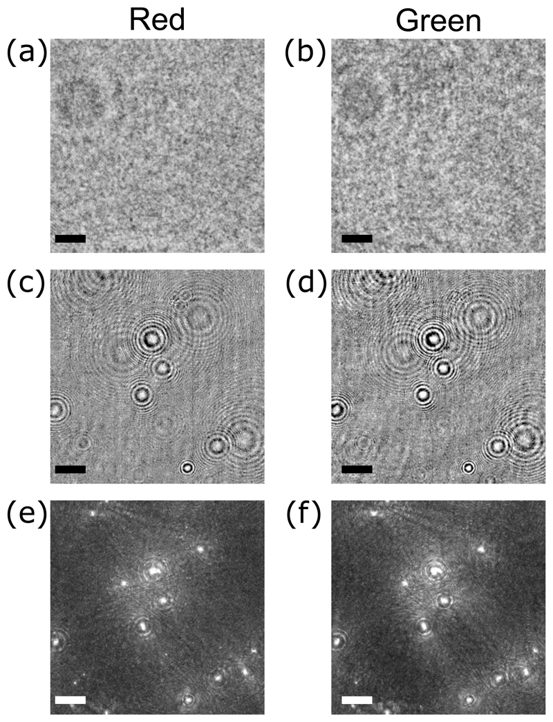
A ‘background’ image Imed (x, y) was obtained from each sub-movie by finding the median pixel value at each location (x, y). Dividing the pixel values in each image in a stack by their background values removed many of the heterogeneities in the background illumination [34]. Example data are shown in Fig. 2, in which a mixture of E. coli bacteria and 0.5 μm diameter polystyrene beads were imaged. Figures 2(c) and (d)show the effect of dividing the raw data by the background image. To reconstruct the three dimensional optical field within the sample at each time point, Iim (x, y, z; t), we used Rayleigh-Sommerfeld back-propagation [34] to generate stacks of 150 refocused images from each frame, in steps of 2 μm from the focal plane (a smaller step size of 0.233 μm was used in the flagellar reconstruction experiments). The calculation of each image plane involved a multiplication in Fourier space, so we took advantage of this by applying a spatial bandpass filter at the same time, passing features between 1 and 30 pixels in size. To identify the objects within Iim (x, y, z; t), we implemented an object localization scheme based on the Gouy phase anomaly, as described elsewhere [45]. Briefly, this approach identifies regions where ∂Iim (x, y, z; t)/∂z is an extremum, as these locations are associated with weakly-scattering objects. Modern high-level programming languages (such as LabVIEW, in which we write our analysis code) offer optimized three-dimensional fast Fourier transforms, which we exploit in this work. We construct an ‘intensity gradient stack’ by the following convolution:
| (1) |
where the Sobel-type gradient operator Sz (x, y, z) is the 3×3×3 array [46] given by:
Fig. 2.
Example two-color holographic images of a mixture of E. coli cells and polystyrene beads (see text), showing intermediate processing steps. Panels (a) and (b) show raw holographic data. The images in panels (c) and (d) show the same data, but with the static background removed (see text). The bottom row shows the maximum intensity projection of the intensity gradient stacks Igrad (x, y, z; t); this data can be used either for image registration or for object localization. The scale bars represent 25 μm in all panels.
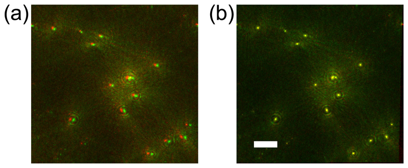
Applying a suitable threshold to the projected image stack resulted in a series of bright points near the center of the objects (data not shown) that were used for image registration. We used a B-spline-based ‘Unwarp’ registration method [47] implemented in Fiji [48] to determine the optimum transformation to map the green data onto the red. Figure 3 shows example data from the red and green channels, superimposed and colored to reflect the channels. The green spots are slightly shifted to the right of the red ones, and the spots are further apart on the right-hand side of the image, indicating a barrel distortion. We note that the magnitude of the distortion is relatively small: the images are shifted by approximately 2.8 μm, and become stretched by a further 2.5 μm, smoothly across an image of around 240 μm, or a cumulative deformation of ~ 1.5%. When the registration transformation had been calculated, we applied the same transformation to the raw (green) image stack, and continued with the rest of the feature extraction procedure. We found image registration in the axial direction to be unneccessary, as the alignment was already very good if the images were registered in the lateral directions before reconstruction.
Fig. 3.
Combining images of a mixture of E. coli cells and polystyrene beads (see text). (a) A superposition of images from red and green channels. The green image is shifted to the right, and suffers a slight stretching in the same direction. (b) A superposition of the red channel with the transformed green channel. The scale bar in panel (b) represents 30 μm. The scale in panel (a) is approximately the same, although red and green channels differ in scale by approximately 1.5% (see text).
4. Object localization
After registration, we crop the image stacks to a region of interest of 256 × 256 pixels, in order to optimize the FFT operations. To minimize the total number of calculations, the Rayleigh-Sommerfeld propagator arrays (including bandpass filter) for each defocus distance, along with the three-dimensional array used to perform the axial intensity gradient operation, are calculated in advance and then applied to each frame in the video sequence. This resulted in a 256×256×150 element (voxel) array, Igrad (x, y, z; t), generated from each movie frame. After calculating Igrad (x, y, z; t) for both red and green channels, we multiply the arrays element-wise to arrive at a ‘joint’ gradient image stack Ijoint (x, y, z; t). This operation eliminates artifacts associated with the object localization technique as outlined below.
Working with relatively dilute samples allows us to project Ijoint (x, y, z) down onto a 2D plane, then use a standard ‘particle identification’ routine to locate the (x, y) centroid position of cells in our sample volume [36]. Example frames, taken from both color channels, are shown in Fig. 2, in which the cells are seen as the bright objects. The cells’ axial positions are then calculated from the full three-dimensional gradient stack by summing a 5×5 pixel region around each cell’s (x, y) centroid position in each z plane and locating the axial point of maximum intensity. While the position of objects in a fully three-dimensional gradient stack can be extracted, the computations are much faster when objects are identified first in two dimensions. The coordinates of the object(s) of interest are identified in each frame, and exported to text files, one per frame of video. These measurements of position are then combined across multiple frames in order to reconstruct the trajectories of cells.
5. Results
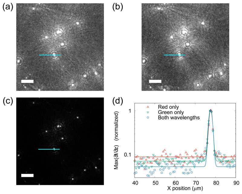
Figure 4 shows maximum intensity projections of our gradient image stacks, from red and green channels individually as well as the joint data. The pixel values in Figs. 4(a–c) are shown with a linear mapping from black for the minimum value, to white for the maximum value. The light blue lines in Fig. 4 represent line profiles of pixel values, which have been plotted in Fig. 4(d). The line profiles trace across the background and a ‘bright’ object of interest. To illustrate the improvement in noise characteristics, the data have been fitted with Gaussian curves, including an offset, and normalized so that the maximum of each curve is 1. This shows the significantly lower background level in the case when both wavelengths are combined (blue circles). Note that the vertical axis in panel 4(d) is on a log scale. The SNRs in this particular case are 11.2, 14.1 and 18.9 for the red, green, and combined cases, respectively.
Fig. 4.
Signal-to-noise ratio improvements using two-color DHM on a mixture of E. coli cells and polystyrene beads. Panels (a) and (b) show maximum intensity projections of gradient stacks from the red and green channels, respectively. Panel (c) shows the effect of multiplying the channels together. Panels (a–c) are displayed using a linear mapping from black for the minimum value, to white for the maximum value. Panel (d) shows a line profile along the path indicated with a light blue line in panels (a–c). The data in panel (d) have been scaled to have a maximum of 1, and fitted with a Gaussian curve (see text), to demonstrate improvements in the SNR. The scale bars in panels (a–c) represent 25 μm.
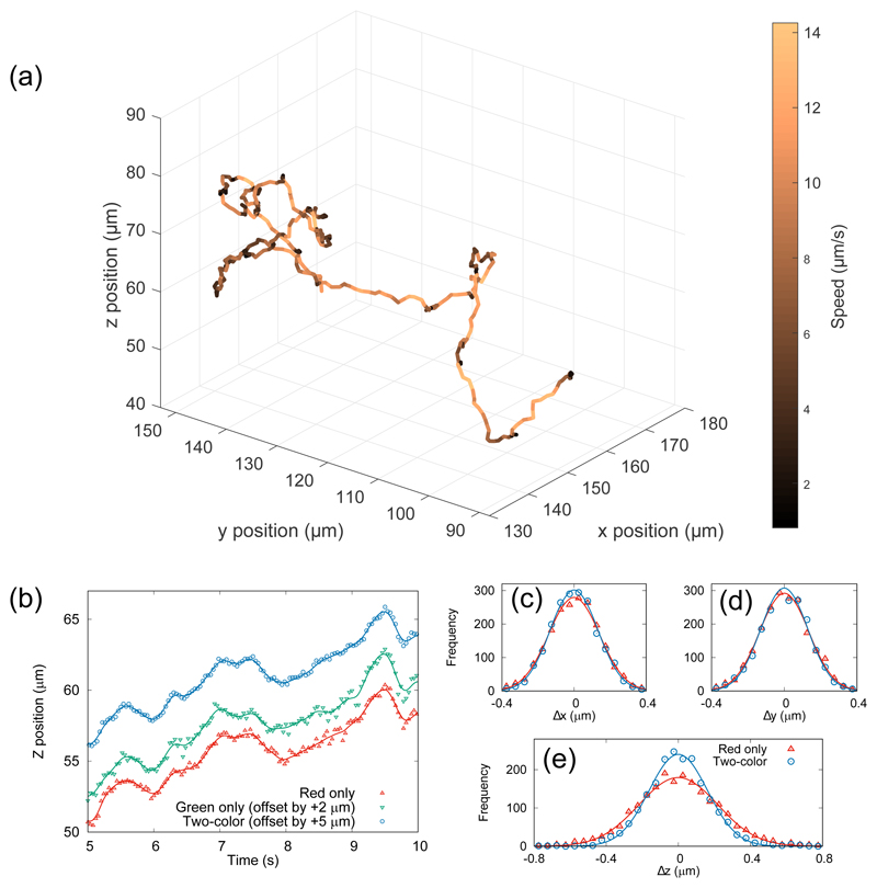
Figure 5(a) shows a three-dimensional trajectory of a swimming E. coli cell, acquired using two-color DHM. The track is color-coded to show instantaneous swimming speed, and every fifth point is plotted for the sake of clarity. Within any bacterial population, there will be a spread of swimming speeds. The cell depicted here is among the slower and more erratic swimmers, but this is beneficial for our purposes because the cell remains inside the field of view for more frames leading to better statistics through a greater range of cell positions, speeds and orientations.
Fig. 5.
(a) A three-dimensional reconstruction of the swimming trajectory of bacterial cell, color-coded with instantaneous swimming speed. The total track duration is 40 seconds. (b) Five seconds of data showing the z-position as a function of time from the red channel only (bottom), the green channel only (middle, offset by 2 μm) and using both channels combined (top, offset by 5 μm). The black lines through the data points show the spline-smoothed track used to characterize the localization noise (see text). (c–e) Histograms of residuals when a spline fit is removed from the three-dimensional trajectory shown in (a). The one- and two-color systems achieve similar accuracy in the plane normal to the optical axis (Δx and Δy), but the two-color method reduces uncertainty in the axial coordinate (Δz), shown by the narrower histogram in panel (e).
To quantify the amount of noise in each cell trajectory, we examine the deviations from a smoothed version of the track. Movement in each orthogonal direction was examined independently, and fit piecewise using cubic splines. The cells are undergoing Brownian motion, which will add some uncertainty in the absolute position measurement, but for an object the size of our cells (~1 μm) in water, the displacement between frames due to Brownian motion (~100 nm in 0.02 s) is much smaller than that due to swimming, so we assume that the high-frequency noise around the smoothed trajectory is due to the detection system only. Example data series (points) and fits (lines) are shown in Fig. 5(b) for one- and two-color DHM, for a five-second subset of data shown in Fig. 5(a). The data show the cell’s position along the optical axis z(t), omitting every second data point. Furthermore, the data series have been offset in the vertical direction as indicated, for clarity.
The data are more scattered around the fit line in the case of one-color DHM. To further quantify this, we examined the distribution of residuals, i.e. differences between the data and the spline fit across the whole 40 second trajectory. Figures 5(c–e) show histograms of these residuals (points), which are symmetrical and well fitted in all cases by Gaussian distribution functions (thick lines). The widths of the distributions are almost identical in x and y, but the standard deviation is reduced by around one third in the z direction. For clarity, the green channel is omitted from the histograms. The red channel gave better performance, and so offered a more competitive comparison with the dual-color version.
A key advantage of the two-color holography system is the reduction in artifacts associated with the axial intensity gradient in the reconstructed volume. This aspect is of particular use when the object of interest is composed of weakly- and strongly-scattering parts. To demonstrate this property, we imaged a cell of L. mexicana. To simplify the analysis of extended objects (such as the flagellum) in three dimensions, the image stacks were calculated with axial steps of 0.233 μm, so that the three-dimensional voxels in the reconstructed stack are cubic.
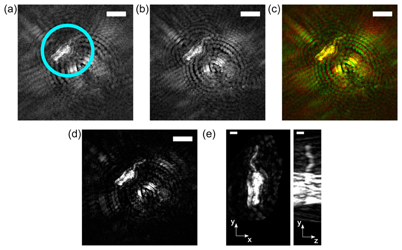
Figures 6(a–d) show maximum-intensity projections of gradient stacks obtained from L. mexicana cells, from red, green and combined channels. The cell can be seen to the top left of the image, highlighted by a light blue circle in Fig. 6(a). The circular features in the center of the image are due to a larger cell somewhat further from the focal plane, which gives rise to characteristic circular artifacts throughout the image. Although the flagellum of the cell (the hair-like structure pointing to the top-right of the image) can be seen by eye in this frame, automatic image segmentation is challenging due to the strength of the artifacts caused by the cell body. The shape of these artifacts, particularly their radius, is ultimately determined by the three-dimensional interference patterns of light within the sample. Crucially, the artifacts are located in different positions when different wavelengths are used to illuminate the sample, and cancel when images from two wavelengths are combined, as shown in Fig. 6(c). The brightness has been enhanced by the same factor in Fig 6(a–d), for ease of comparison.
Fig. 6.
Example data acquired from a subject with heterogeneous scattering properties: a promastigote L. mexicana cell. (a) and (b) show the red and green maximum intensity projection images, respectively (scale bar = 10 μm in each). Panel (c) shows a color image with the red and green channels combined, so that the artifacts can be seen to lie in different positions in each channel. Panel (d) shows the maximum intensity projection of the registered ‘joint’ image (scale bar = 10 μm), and panel (e) shows two orthogonal projections of the cell, demonstrating the three-dimensional reconstruction of the flagellum, the hair-like projection at the top of the cell (scale bar = 2 μm).
Figure 6 shows a magnified and re-oriented version of the same cell (note that the scale bar represents 2 μm here, and 10 μm in Fig. 6(a–c), in both top-down and side-on views, demonstrating the fully three-dimensional shape of the flagellum. The brightness of this image has been increased in order to highlight the flagellum, while saturating the cell body (the true length of the body is approximately 6 μm). Both cell body and flagellum can be located independently, by performing successive thresholding operations (data not shown).
6. Conclusions
We have demonstrated that our implementation of two-color DHM has significant advantages over its one-color counterpart, particularly for optically inhomogeneous objects. We have demonstrated this ability by imaging a long, flexible object: the flagellum of a freely-swimming cell of the pathogenic microorganism Leishmania mexicana. DHM imaging of this object is usually hampered by the adjacent cell body that scatters much more light than the flagellum. Our system is relatively easy to implement, particularly in an ‘in-line’ configuration, where mature technologies such as fiber WDM devices can be used to combine lasers in an existing setup. The use of an adapter to allow red and green channels to be imaged on the same sensor is advantageous in that it allows shorter exposure times than those that would be possible on a color sensor, and a simplified analysis. The adapter introduces small distortions as described above, but these are straightforward to correct as described in the calibration step in section 3. We anticipate that this registration protocol may also be of interest to those working in the allied field of quantitative phase imaging. Our main result is that the two-color method can be used to reduce twin-image artifacts, particularly when using localization methods based on the Gouy phase anomaly. In addition to this, we have demonstrated that the final arrangement improves the SNR in tracking the axial position of single cells by around one third. We contend that the continuing development of DHM, through refinements such as the use of multiple wavelengths or tilted illumination, holds great promise for high-speed, quantitative studies of the dynamics of microorganisms.
Acknowledgments
The data underlying this paper can be found at doi:10.15124/5d61ce08-7ec5-4981-9980-fd4cc8a1b578
Funding
Engineering and Physical Sciences Research Council (EPSRC) (EP/N014731/1); Medical Research Council (MRC) (MR/L00092X/1); Wellcome Trust (WT105502MA).
Footnotes
Disclosures
The authors declare that there are no conflicts of interest related to this article.
References and links
- 1.Goodman J, Lawrence RW. Digital image formation from electronically detected holograms. Appl Phys Lett. 1967;11:77–79. [Google Scholar]
- 2.Schnars U, Jüptner W. Direct recording of holograms by a ccd target and numerical reconstruction. Appl Opt. 1994;33:179–181. doi: 10.1364/AO.33.000179. [DOI] [PubMed] [Google Scholar]
- 3.Haddad WS, Cullen D, Solem JC, Longworth JW, McPherson A, Boyer K, Rhodes CK. Fourier-transform holographic microscope. Appl Opt. 1992;31:4973–4978. doi: 10.1364/AO.31.004973. [DOI] [PubMed] [Google Scholar]
- 4.Kim M. Principles and techniques of digital holographic microscopy. SPIE Rev. 2010;1 018005. [Google Scholar]
- 5.Xu W, Jericho MH, Meinertzhagen IA, Kreuzer HJ. Digital in-line holography for biological applications. Proc Natl Acad Sci. 2001;98:11301–11305. doi: 10.1073/pnas.191361398. [DOI] [PMC free article] [PubMed] [Google Scholar]
- 6.DiCaprio G, Coppola G, Stefano LD, Stefano MD, Antonucci A, Congestri R, Tommasi ED. Shedding light on diatom photonics by means of digital holography. J Biophotonics. 2012;7:341–350. doi: 10.1002/jbio.201200198. [DOI] [PubMed] [Google Scholar]
- 7.Kemper B, von Bally G. Digital holographic microscopy for live cell applications and technical inspection. Appl Optics. 2008;47:A52–A61. doi: 10.1364/ao.47.000a52. [DOI] [PubMed] [Google Scholar]
- 8.Su T, Xue L, Ozcan A. High-throughput lensfree 3d tracking of human sperms reveals rare statistics of helical trajectories. Proc Natl Acad Sci. 2012;109:16018–16022. doi: 10.1073/pnas.1212506109. [DOI] [PMC free article] [PubMed] [Google Scholar]
- 9.Boss D, Hoffmann A, Rappaz B, Depeursinge C, Magistretti PJ, van de Ville D, Marquet P. Spatially-resolved eigenmode decomposition of red blood cells membrane fluctuations questions the role of atp in flickering. PLoS One. 2012;7:e40667. doi: 10.1371/journal.pone.0040667. [DOI] [PMC free article] [PubMed] [Google Scholar]
- 10.DiCaprio G, El Mallahi A, Ferraro P, Dale R, Coppola G, Dale B, Coppola G, Dubois F. 4d tracking of clinical seminal samples for quantitative characterization of motility parameters. Biomed Opt Express. 2014;5:690–700. doi: 10.1364/BOE.5.000690. [DOI] [PMC free article] [PubMed] [Google Scholar]
- 11.Park H, Lee S-H, Kim K, Cho S-H, Lee W-J, Kim LY, Lee S-E, Park Y. Characterizations of individual mouse red blood cells parasitized by babesia microti using 3-d holographic microscopy. Sci Rep. 2015;5 doi: 10.1038/srep10827. 10827. [DOI] [PMC free article] [PubMed] [Google Scholar]
- 12.Jikeli JF, Alvarez L, Friedrich BM, Wilson LG, Pascal R, Colin R, Pichlo M, Rennhack A, Brenker C, Kaupp UB. Sperm navigation along helical paths in 3d chemoattractant landscapes. Nat Commun. 2015;6 doi: 10.1038/ncomms8985. 7985. [DOI] [PMC free article] [PubMed] [Google Scholar]
- 13.Xu M, Jericho MH, Kreuzer HJ, Meinertzhagen IA. Tracking particles in four dimensions with in-line holographic microscopy. Opt Lett. 2003;28:164–166. doi: 10.1364/ol.28.000164. [DOI] [PubMed] [Google Scholar]
- 14.Garcia-Sucerquia J, Xu W, Jericho SK, Klages P, Jericho MH, Kreuzer HJ. Digital in-line holographic microscopy. Appl Optics. 2006;45:836–850. doi: 10.1364/ao.45.000836. [DOI] [PubMed] [Google Scholar]
- 15.Sheng J, Malkiel E, Katz J, Adolf J, Belas R, Place AR. Digital holographic microscopy reveals prey-induced changes in swimming behavior of predatory dinoflagellates. Proc Natl Acad Sci. 2007;104:17512–17517. doi: 10.1073/pnas.0704658104. [DOI] [PMC free article] [PubMed] [Google Scholar]
- 16.El Mallahi A, Minetti C, Dubois F. Automated three-dimensional detection and classification of living organisms using digital holographic microscopy with partial spatial coherent source: application to the monitoring of drinking water resources. Appl Optics. 2013;52:A68–A80. doi: 10.1364/AO.52.000A68. [DOI] [PubMed] [Google Scholar]
- 17.Wilson LG, Carter LM, Reece SE. High-speed holographic microscopy of malaria parasites reveals ambidextrous flagellar waveforms. Proc Natl Acad Sci USA. 2013;110:18769–18774. doi: 10.1073/pnas.1309934110. [DOI] [PMC free article] [PubMed] [Google Scholar]
- 18.Thornton KL, Findlay RC, Walrad PB, Wilson LG. Investigating the swimming of microbial pathogens using digital holography. Adv Exp Med Biol. 2016;915:17–32. doi: 10.1007/978-3-319-32189-9_3. [DOI] [PubMed] [Google Scholar]
- 19.Jericho MH, Kreuzer HJ, Kanka M, Riesenberg R. Quantitative phase and refractive index measurements with point-source digital in-line holographic microscopy. Appl Opt. 2012;51:1503–1515. doi: 10.1364/AO.51.001503. [DOI] [PubMed] [Google Scholar]
- 20.Molaei M, Barry M, Stocker R, Sheng J. Failed escape: Solid surfaces prevent tumbling of escherichia coli. Phys Rev Lett. 2014;113 doi: 10.1103/PhysRevLett.113.068103. 068103. [DOI] [PubMed] [Google Scholar]
- 21.Giuliano CB, Zhang R, Wilson LG. Digital inline holographic microscopy (dihm) of weakly-scattering subjects. J Vis Exp. 2014;84:e50488. doi: 10.3791/50488. [DOI] [PMC free article] [PubMed] [Google Scholar]
- 22.Cheong FC, Wong CC, Gao YF, Nai MH, Cui Y, Park S, Kenney LJ, Lim CT. Rapid, high-throughput tracking of bacterial motility in 3d via phase-contrast holographic video microscopy. Biophys J. 2016;108:1248–1256. doi: 10.1016/j.bpj.2015.01.018. [DOI] [PMC free article] [PubMed] [Google Scholar]
- 23.Nadeau JL, Cho YB, Kühn J, Liewer K. Improved tracking and resolution of bacteria in holographic microscopy using dye and fluorescent protein labeling. Front Chem. 2016;4:17. doi: 10.3389/fchem.2016.00017. [DOI] [PMC free article] [PubMed] [Google Scholar]
- 24.Wang A, Garmann RF, Manoharan VN. Tracking e. coli runs and tumbles with scattering solutions and digital holographic microscopy. Opt Express. 2017;24:23719–23725. doi: 10.1364/OE.24.023719. [DOI] [PubMed] [Google Scholar]
- 25.Bianchi S, Saglimbeni F, Di Leonardo R. Holographic imaging reveals the mechanism of wall entrapment in swimming bacteria. Phys Rev X. 2017;7 011010. [Google Scholar]
- 26.Charrière F, Rappaz B, Kühn J, Colomb T, Marquet P, Depeursinge C. Influence of shot noise on phase measurement accuracy in digital holographic microscopy. Opt Express. 2007;15:8818–8831. doi: 10.1364/oe.15.008818. [DOI] [PubMed] [Google Scholar]
- 27.Cuche E, Bevilacqua F, Depeursinge C. Digital holography for quantitative phase-contrast imaging. Opt Lett. 1999;24:291–293. doi: 10.1364/ol.24.000291. [DOI] [PubMed] [Google Scholar]
- 28.Yamaguchi I, Kato J-I, Ohta S, Mizuno J. Image formation in phase-shifting digital holography and applications to microscopy. Appl Optics. 2001;40:6177–6186. doi: 10.1364/ao.40.006177. [DOI] [PubMed] [Google Scholar]
- 29.Kühn J, Colomb T, Montfort F, Charrière F, Emery Y, Cuche E, Marquet P, Depeursinge C. Real-time dual-wavelength digital holographic microscopy with a single hologram acquisition. Opt Express. 2007;15:7231–7242. doi: 10.1364/oe.15.007231. [DOI] [PubMed] [Google Scholar]
- 30.Fu Y, Pedrini G, Hennelly BM, Groves RM, Osten W. Dual-wavelength image-plane digital holography for dynamic measurement. Opt Laser Eng. 2009;47:552–557. [Google Scholar]
- 31.Abdelsalam DG, Kim D. Real-time dual-wavelength digital holographic microscopy based on polarizing separation. Opt Commun. 2012;285:233–237. [Google Scholar]
- 32.Lee S, Roichman Y, Yi G-R, Kim S-H, Yang S-M, van Blaaderen A, van Oostrum P, Grier DG. Characterizing and tracking single colloidal particles with video holographic microscopy. Opt Express. 2007;15:18275–18282. doi: 10.1364/oe.15.018275. [DOI] [PubMed] [Google Scholar]
- 33.Fung J, Martin KE, Perry RW, Katz DM, McGorty R, Manoharan VN. Measuring translational, rotational, and vibrational dynamics in colloids with digital holographic microscopy. Opt Express. 2011;19:8051–8065. doi: 10.1364/OE.19.008051. [DOI] [PubMed] [Google Scholar]
- 34.Lee S-H, Grier DG. Holographic microscopy of holographically trapped three-dimensional structures. Opt Express. 2007;15:1505–1512. doi: 10.1364/oe.15.001505. [DOI] [PubMed] [Google Scholar]
- 35.Saglimbeni F, Bianchi S, Lepore A, Di Leonardo R. Three-axis digital holographic microscopy for high speed volumetric imaging. Opt Express. 2014;22:13710–13718. doi: 10.1364/OE.22.013710. [DOI] [PubMed] [Google Scholar]
- 36.Sheng J, Malkiel E, Katz J. Digital holographic microscope for measuring three-dimensional particle distributions and motions. Appl Opt. 2006;45:3893–3901. doi: 10.1364/ao.45.003893. [DOI] [PubMed] [Google Scholar]
- 37.Langehanenberg P, Kemper B, Dirksen D, von Bally G. Autofocusing in digital holographic phase contrast microscopy on pure phase objects for live cell imaging. Appl Opt. 2008;47:D176–D182. doi: 10.1364/ao.47.00d176. [DOI] [PubMed] [Google Scholar]
- 38.De Pablos LM, Ferreira TR, Walrad PB. Developmental differentiation in leishmania lifecycle progression: post-transcriptional control conducts the orchestra. Curr Opin Microbiol. 2016;34:82–89. doi: 10.1016/j.mib.2016.08.004. [DOI] [PubMed] [Google Scholar]
- 39.Wiese M, Kuhn D, Grünfelder CG. Protein kinase involved in flagellar-length control. Eukaryot Cell. 2003;2:769–777. doi: 10.1128/EC.2.4.769-777.2003. [DOI] [PMC free article] [PubMed] [Google Scholar]
- 40.Gadelha C, Wickstead B, Gull K. Flagellar and ciliary beating in trypanosome motility. Cell Mot Cytoskel. 2007;64:629–643. doi: 10.1002/cm.20210. [DOI] [PubMed] [Google Scholar]
- 41.Tahara T, Kakue T, Awatsuji Y, Nishio K, Ura S, Kubota T, Matoba O. Parallel phase-shifting color digital holographic microscopy. 3D Research. 2010;1:25. doi: 10.1364/BOE.1.000610. [DOI] [PMC free article] [PubMed] [Google Scholar]
- 42.Isikman SO, Greenbaum A, Luo W, Coskun AF, Ozcan A. Giga-pixel lensfree holographic microscopy and tomography using color image sensors. PLoS One. 2012;7:e45044. doi: 10.1371/journal.pone.0045044. [DOI] [PMC free article] [PubMed] [Google Scholar]
- 43.Wu Y, Zhang Y, Luo W, Ozcan A. Demosaiced pixel super-resolution for multiplexed holographic color imaging. Sci Rep-UK. 2016;6 doi: 10.1038/srep28601. 28601. [DOI] [PMC free article] [PubMed] [Google Scholar]
- 44.Berg HC, Brown DA. Chemotaxis in escherichia coli analysed by three-dimensional tracking. Nature. 1972;239:500. doi: 10.1038/239500a0. [DOI] [PubMed] [Google Scholar]
- 45.Wilson L, Zhang R. 3d localization of weak scatterers in digital holographic microscopy using rayleigh-sommerfeld back-propagation. Opt Express. 2012;20:16735–16744. [Google Scholar]
- 46.Engel K, Hadwiger M, Kniss JM, Rezk-Salama C, Weiskopf D. Real-time volume graphics. A.K. Peters Ltd; 2006. [Google Scholar]
- 47.Sorzano CÓS, Thévenaz P, Unser M. Elastic registration of biological images using vector-spline regularization. IEEE T Bio-Med Eng. 2005;52:652–663. doi: 10.1109/TBME.2005.844030. [DOI] [PubMed] [Google Scholar]
- 48.Schindelin J, Arganda-Carreras I, Frise E, Kaynig V, Longair M, Pietzsch T, Preibisch S, Rueden C, Saalfeld S, Schmid B, Tinevez JY, et al. Fiji: an open-source platform for biological-image analysis. Nature Met. 2012;9:676–682. doi: 10.1038/nmeth.2019. [DOI] [PMC free article] [PubMed] [Google Scholar]


