 A flexible twofold interpenetrated MOF reversibly switches between closed, narrow and large pore forms. In situ crystallographic analysis of a narrow-pore intermediate phase provides a detailed explanation of a plateau observed during desorption.
Abstract
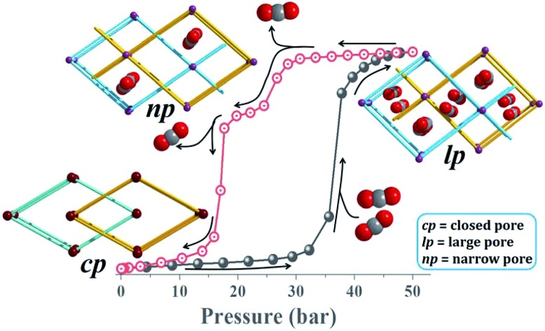
A molecular-level investigation is reported on breathing behaviour of a metal–organic framework (1) in response to CO2 gas pressure. High-pressure gas adsorption shows a pronounced step corresponding to a gate-opening phase transformation from a closed (1cp) to a large-pore (1lp) form. A plateau is observed upon desorption corresponding to narrow-pore intermediate form 1np which does not occur during adsorption. These events are corroborated by pressure-gradient differential scanning calorimetry and in situ single-crystal X-ray diffraction analysis under controlled CO2 gas pressure. Complete crystallographic characterisation facilitated a rationalisation of each phase transformation in the series 1cp → 1lp → 1np → 1cp during adsorption and subsequent desorption. Metropolis grand-canonical Monte Carlo simulations and DFT-PBE-D3 interaction energy calculations strongly underpin this first detailed structural investigation of an intermediate phase encountered upon desorption.
Introduction
Metal–organic frameworks (MOFs) have emerged as a distinct new class of porous materials of potential importance for various applications.1 Flexible MOFs offer the possibility of stimulus-responsive dynamic behaviour,2 and thus hold distinct advantages over conventional rigid porous materials such as activated carbons and zeolites. The flexibility of a MOF depends on several factors, such as the nature of the organic ligands, cleavage and regeneration of coordination bonds, and interaction between interpenetrated subnets.3 The dynamic behaviour of such “soft porous crystals” (as described by Kitagawa)4 is often due to transformations between multiple stable states of the flexible framework. Therefore, understanding the multiple structural changes in a dynamic MOF in response to external stimuli (e.g. guest removal or exchange, gas pressure, mechanical force, temperature)1b,3a,5 is not only interesting but also highly desirable for the design of materials with potential for storage,6 separation,7 sensing,8 and other related applications.9 It should be noted that, among the plethora of reported MOFs, only a limited number exhibit dynamic behaviour such as expansion/shrinkage of the framework10 or opening/closing of pores,11 giving rise to reversible changes in their physicochemical properties.12 This is because tailoring framework flexibility is much more challenging than controlling static structural features such as framework topology and pore size/shape.13 Appreciating the obvious relationship between framework flexibility and host structure, we have successfully employed the strategy of using flexible organic linkers to imbue the framework with dynamic behaviour, both locally and overall.14
It should be noted that MOFs exhibiting dynamic behaviour pose a great challenge in terms of extracting atomic-level structural information on their dynamics.15 Owing to the loss of crystal singularity that commonly occurs upon transformation between multiple stable states, single crystal X-ray diffraction (SCD) analysis is often not an option. The most credible structural information must therefore be derived from powder X-ray diffraction (PXRD) and other supporting analyses.16
Here we report structural analysis of a flexible MOF constructed from 1,2-bis-(4-pyridyl)ethane (bpa, with a flexible ethylene bridge) and 1,4-naphthalene dicarboxylic acid (ndcH2, with a rotatable aromatic ring). Solvothermal reaction of Zn(NO3)2·6H2O, ndcH2 and bpa in a 1 : 1 : 1 molar ratio, following the procedure reported by Li et al.,17 afforded the twofold interpenetrated 3D framework [Zn2(ndc)2(bpa)]n, hereafter referred to as 1. Interestingly, the as-synthesised structure (1cp; cp = closed pore) does not possess any guest-accessible space, as evidenced by the absence of solvent molecules. Nevertheless, high pressure gas sorption analysis reveals that 1cp undergoes stimulus-driven breathing behaviour to an open phase under CO2 gas pressure at 298 K. Moreover, the structural transformation occurs in single-crystal to single-crystal fashion. We note that Kanoo et al. recently reported the related 3D coordination polymer {[Zn2(ndc)2(bpa)]·solvent}n which, upon activation, yields a framework with the same topology as that of 1cp.18 However, the activated form of this framework is crystallographically different from 1cp and the authors also reported that it does not exhibit any CO2 adsorption at 293 K.
In an attempt to visualise the structural transformation of the host, as well as the mode of interaction between CO2 guest molecules and the host framework, SCD analysis of the same crystal was carried out under controlled CO2 gas pressure at 298 K using an environmental gas cell. The sorption and SCD results are also well supported by pressure-gradient differential scanning calorimetry (PGDSC) and variable-pressure powder X-ray diffraction (VP-PXRD) analysis. Theoretical calculations provide further insight into the dynamic behaviour.
Results and discussion
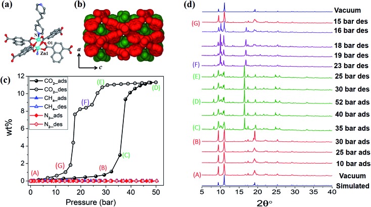
1cp crystallises in the orthorhombic space group Fmmm and consists of {Zn2(COO)4} paddlewheel secondary building units (SBU) with square pyramidal zinc centres coordinated to four oxygen atoms from four different ndc ligands at the basal positions, and one nitrogen atom from a bpa molecule at the apical position (Fig. 1a and Table S1†). The SBUs are linked in the ac plane by ndc ligands to generate rhombic 2D nets (Fig. S1a†) that are pillared by bpa along the b axis to generate a 3D framework with α-polonium net topology. Each net is large enough to accommodate another net, thus leading to the formation of a twofold interpenetrated framework (Fig. 1b). Each of the ndc naphthalene moieties in 1cp is fourfold disordered (Fig. S2b†) while bpa displays twofold disorder (Fig. S2c†). As 1cp is a dense structure, the interpenetrated networks are in close proximity and interact with each other by means of C–H···O (dC···O = 3.437(12) Å) and C–H···π (dH···π = 3.321(9) Å) interactions (Fig. S2d†).
Fig. 1. (a) Coordination environment of Zn(ii) in 1cp. (b) Spacefilling view along [010] showing the twofold entanglement of 1cp and its lack of guest-accessible space. (c) Adsorption (filled symbols) and desorption (open symbols) isotherms for 1 recorded at 298 K with test gases CO2, CH4 and N2. (d) PXRD patterns of 1 under variable CO2 gas pressure at 298 K.
Although the as-synthesised framework does not possess any cavity or open channel, it is known that carboxylate-linked paddlewheel SBUs are conducive to dynamic behaviour.2c,19 Such phase transitions are generally accompanied by “kneecap” rotation about the O···O axis of the carboxylate groups, which facilitates reorientation of the SBUs while maintaining their interconnectivity.2a,20 Furthermore, phenylene spacers can rotate in the presence of suitable external stimuli, thus allowing an increase in accessible space.
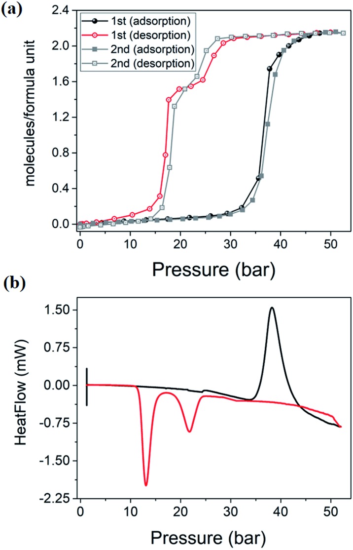
High-pressure sorption/desorption analyses with N2, CH4, and CO2 were carried out at 298 K using a single sample of 1cp (Fig. 1c). The isotherms reveal negligible uptake of N2 and CH4 at 50 bar. However, the CO2 sorption profile shows gated uptake with a large hysteresis loop in the desorption curve. Modest uptake occurs until a threshold pressure of 32 bar is reached (point B in Fig. 1c), after which there is a sharp increase in uptake with a saturation plateau at 50 bar, corresponding to a capacity of 11.5 wt%, or two CO2 molecules per host formula unit (point D). The sudden uptake after 32 bar hints at a phase change from a nonporous to a porous phase. The desorption profile is significantly different from the adsorption profile. Pronounced hysteresis suggests strong interaction of the channel surface with trapped CO2 molecules, which are retained down to 28 bar during desorption (point E). Moreover, the desorption isotherm features two steps with a plateau that implies a metastable phase with a capacity of 8.2 wt%, or 1.5 CO2 molecules per formula unit (point F). This is evidence for a CO2-induced structural transformation of one open phase to a different open phase. All of the CO2 is released upon further decreasing the pressure and the salient features of the isotherms are also present in a subsequent adsorption/desorption cycle (Fig. 2a).
Fig. 2. (a) Two consecutive cycles of CO2 adsorption/desorption for 1 at 298 K. (b) PGDSC trace showing thermal events corresponding to inflections observed during adsorption (black) and desorption (red) in the isotherm.
PGDSC measurements were also carried out for 1cp exposed to CO2 in the pressure range 1–50 bar at 298 K (Fig. 2b).14c,21 During adsorption an exothermic peak occurs with an onset pressure of 35 bar, corresponding to the sudden uptake of CO2 observed in the adsorption isotherm. The integrated heat of –23.69 kJ mol–1 for this event includes the heat of adsorption along with a small contribution from the associated structural change. During desorption, endothermic events occur with onset pressures of 23 and 15 bar, with associated energies of 13.07 and 37.66 kJ mol–1, respectively, spanning the plateau observed in the desorption isotherm.
The “breathing” effect was further investigated using VP-PXRD. As shown in Fig. 1d, no change is observed in the diffractograms until 35 bar of CO2 pressure, after which a distinct change is observed that corresponds to point C in the sorption isotherm (Fig. 1c). The diffractograms then remain unchanged until 52 bar is reached and, upon decreasing the pressure, a change is observed at 23 bar, which corresponds to point F on the desorption profile. This PXRD pattern does not resemble that of either the fully loaded or the as-synthesised structures, thus indicating a new phase. This phase persists until 15 bar (point G), after which the diffractogram resembles that of the as-synthesised 1cp (down to vacuum).
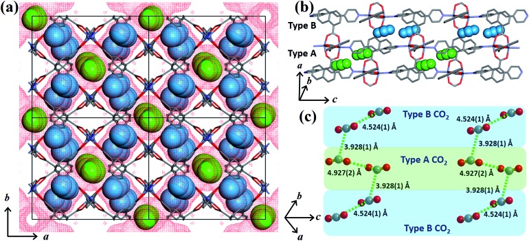
In order to obtain detailed structural information regarding the CO2 sorption sites and loading-induced changes to the framework, in situ VP-SCD studies were carried out on 1cp under controlled CO2 gas pressures using an environmental gas cell.22 Although the onset of the first structural change occurs at 35 bar (as evident from VP-PXRD analysis), the saturation pressure of 50 bar was used. The crystal retains its singularity at this pressure and structural characterisation reveals a single-crystal to single-crystal phase transition from 1cp to a large pore phase 1lp with the formula {[Zn2(ndc)2(bpa)]·2CO2}n (Table S1†). Significant relative movement of the two interpenetrated nets is accompanied by a decrease in space group symmetry from orthorhombic Fmmm to monoclinic C2/c. The phase transition 1cp → 1lp resembles the unfolding of an articulated wine-rack.3b Although the SBU and the framework topology remain unchanged, the acute angle (θ1) between ndc ligands increases from 59.747(8)° to 81.621(7)° (Fig. S6 and Table S2†). The movement of the interpenetrated nets relative to each other with concomitant changes in the conformation of the linkers results in the formation of guest-accessible space in 1lp. Two crystallographically unique CO2 molecules (labelled A and B, Fig. 3) are located in the 3D guest-accessible space of 1lp and like types repeat along [001]. The dC···C separations between the pseudo-slipped-parallel arranged CO2 molecules are in the range 3.928(1) to 4.927(2) Å (Fig. 3c). The prefix “pseudo” distinguishes the arrangements in 1lp from the idealised arrangements in dry ice.23 The CO2 molecules form strong electrostatic interactions with the framework. The nearest contacts between carbon atoms of CO2 molecules and oxygen atoms of the carboxylate groups are 3.465(9) and 3.63(1) Å for types A and B, respectively (Fig. S8†). Close contacts also occur between CO2 molecules and the hydrogen atoms of the naphthalene groups, as well as those of the ethylene bridges (Table S3†).
Fig. 3. (a) View of 1lp along [001]. The guest-accessible space27 is shown as red dots while type A and B CO2 molecules (in spacefilling representation) are coloured green and blue, respectively. (b) and (c) Perspective views of the pseudo-slipped-parallel arrangement of the CO2 molecules with dC···C separations indicated. Hydrogen atoms are omitted for clarity.
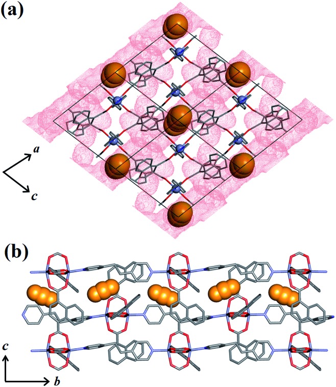
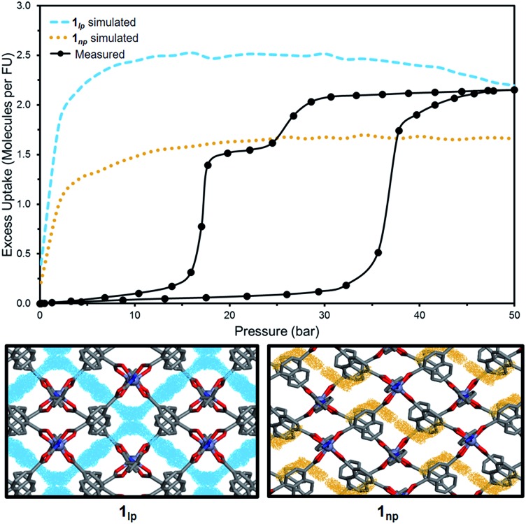
To investigate the phase changes occurring upon desorption, the pressure was reduced from 50 to 23 bar. In situ VP-SCD analysis was again carried out using the same crystal. Very few reports exist that describe desorption VP-PXRD analysis of flexible MOFs.2a,16 However, to the best of our knowledge, this is the first detailed SCD investigation on an intermediate phase obtained upon desorption. At 23 bar the space group changes to P21/m and further adjustment of the two nets (Fig. S6 and Table S2†) yields the narrow pore (1np) form {[Zn2(ndc)2(bpa)]·1.5CO2}n.28 The 3D accessible space in 1lp transforms into discrete voids (Fig. 4). Although it was only possible to model one CO2 molecule, the difference map reveals the presence of residual electron density consistent with the presence of unmodelled diffuse CO2. Metropolis24 grand-canonical Monte Carlo simulations corroborate the measured sorption capacity of 1.5 CO2 molecules per formula unit of 1np (Fig. 5).
Fig. 4. (a) View of 1np along [010] with the guest-accessible void surfaces27 shown as red dots and CO2 molecules in spacefilling representation. (b) View of 1np along [100] showing propagation of CO2 molecules in the crystallographic b direction. Hydrogen atoms are omitted for clarity.
Fig. 5. Comparison of experimental and simulated excess CO2 uptake at 298 K for 1lp (blue) and 1np (orange) with corresponding simulated probability density maps at 50 and 23 bar, respectively.
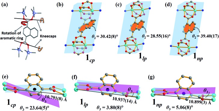
The breathing mechanism is derived from two principal deformations of the framework (Fig. 6a). The dihedral angle θ2 between the naphthalene ring and the plane passing through the four Zn atoms (as shown in Fig. 6b–d) changes owing to linker rotation. The O···O vector of the carboxylate group acts as a “kneecap” around which the SBUs can rotate during the phase transformation. This hinge-like motion changes the dihedral angle θ3 between the plane passing through all four oxygen atoms of ndc and that between two oxygen and two zinc atoms of the SBU (blue and pink plane in Fig. 6e–g, respectively).
Fig. 6. (a) Schematic representations of the two factors governing the breathing behaviour in 1: (b–d) rotation of the naphthalene rings (orange) relative to the plane between the four Zn ions (blue) and (e–g) kneecap hinge motion between planes passing through the ndc oxygen atoms (blue) and the Zn2O2 moiety (pink) of the SBU.
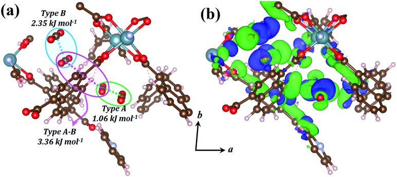
The host–guest and guest–guest interactions involving the two types of CO2 molecules in 1lp were investigated theoretically in order to rationalise the occurrence of the intermediate phase 1np during desorption. Periodic unit cell and geometry optimisations of a 1 × 1 × 1 representation for 1lp and 1np showed negligible changes in cell parameters and atomic positions, confirming the suitability of the DFT-PBE-D3/double-zeta level of theory (Table S5, Fig. S12 and S13†).25 Counterpoise-corrected26 host–guest interaction energies of 40.09 and 34.35 kJ mol–1 were calculated for the type A and B CO2 molecules of 1lp, respectively (Table S6†). Favourable binary guest–guest interaction energies between two type A, two type B and between type A and type B CO2 molecules amount to 1.06, 2.35 and 3.36 kJ mol–1, respectively (Fig. 7a). Computed electron density difference maps (EDDMs) for 1lp reveal interactions between the π systems of type A CO2 molecules and aromatic C–H bonds of ndc, while type B CO2 molecules interact strongly with carboxylate oxygen atoms (Fig. 7b; see ESI for more details and Fig. S14† for geometry-optimised dC···C separations). Collectively these and other factors such as channel shape and surface potential differences explain why CO2 molecules are retained until 28 bar during desorption, thus accounting for the hysteresis observed in Fig. 1c. The host–guest interaction energy of 40.67 kJ mol–1 calculated for 1np (Table S6†) is consistent with the observation that only a fraction of the CO2 molecules are removed during the transition from 1lp to 1np. The latter persists until 15 bar, after which the VP-PXRD diffractogram again resembles that of 1cp (Fig. 1d).
Fig. 7. (a) Perspective view showing CO2 positions within the geometry-optimised structure of 1lp with guest–guest interaction energies between different combinations of two CO2 molecules. (b) EDDM showing areas of enhanced (green) and depleted (blue) electron density of the geometry-optimised structure of 1lp with respect to its isolated MOF and CO2 components. The EDDM was generated for a periodic 1 × 1 × 1 unit cell and only a fragment is shown for clarity.
Conclusion
We report three CO2 pressure-induced forms of a flexible, twofold interpenetrated pillared-layered MOF that reversibly switches between closed-, narrow- and large-pore forms. All of these forms have been characterised structurally using in situ SCD analysis. The transformation is brought about by CO2 but not by N2 or CH4 in the pressure range 0–50 bar at 298 K. Inflections observed in the sorption isotherm are consistent with PGDSC and VP-PXRD analyses. This study describes the first SCD analysis of an intermediate phase that is only accessible during desorption. Using complementary theoretical evaluations, we provide a molecular-level explanation for the plateau observed in the desorption isotherm. Not only do the results presented here provide considerable new insight into the breathing behaviour of a flexible MOF, but they also offer opportunities to develop a new class of materials where the structure–property relationships can be exploited in molecular recognition.
Conflicts of interest
There are no conflicts to declare.
Supplementary Material
Acknowledgments
We thank the National Research Foundation of South Africa and Stellenbosch University (Subcommittee B) for financial support and the Centre for High Performance Computing (CHPC) in Cape Town for the use of their computational resources.
Footnotes
†Electronic supplementary information (ESI) available: Synthetic procedure, thermogravimetric analysis, additional figures, single-crystal and powder X-ray diffraction results, and computational details. CCDC: 1944820–1944823. For ESI and crystallographic data in CIF or other electronic format see DOI: 10.1039/c9sc04043a
References
- (a) Furukawa H., Cordova K. E., O'Keeffe M., Yaghi O. M. Science. 2013;341:1230444. doi: 10.1126/science.1230444. [DOI] [PubMed] [Google Scholar]; (b) Kitagawa S., Kitaura R., Noro S.-i. Angew. Chem., Int. Ed. 2004;43:2334. doi: 10.1002/anie.200300610. [DOI] [PubMed] [Google Scholar]
- (a) Zhu A.-X., Yang Q.-Y., Kumar A., Crowley C., Mukherjee S., Chen K.-J., Wang S.-Q., O′Nolan D., Shivanna M., Zaworotko M. J. J. Am. Chem. Soc. 2018;140:15572. doi: 10.1021/jacs.8b08642. [DOI] [PubMed] [Google Scholar]; (b) Rabone J., Yue Y. F., Chong S. Y., Stylianou K. C., Bacsa J., Bradshaw D., Darling G. R., Berry N. G., Khimyak Y. Z., Ganin A. Y., Wiper P., Claridge J. B., Rosseinsky M. J. Science. 2010;329:1053. doi: 10.1126/science.1190672. [DOI] [PubMed] [Google Scholar]; (c) Schneemann A., Bon V., Schwedler I., Senkovska I., Kaskel S., Fischer R. A. Chem. Soc. Rev. 2014;43:6062. doi: 10.1039/c4cs00101j. [DOI] [PubMed] [Google Scholar]; (d) Haldar R., Sikdar N., Maji T. K. Mater. Today. 2015;18:97. [Google Scholar]; (e) Maji T. K., Matsuda R., Kitagawa S. Nat. Mater. 2007;6:142. doi: 10.1038/nmat1827. [DOI] [PubMed] [Google Scholar]; (f) Wang X.-N., Zhang P., Kirchon A., Li J.-L., Chen W.-M., Zhao Y.-M., Li B., Zhou H.-C. J. Am. Chem. Soc. 2019;141:13654. doi: 10.1021/jacs.9b06711. [DOI] [PubMed] [Google Scholar]
- (a) Férey G., Serre C. Chem. Soc. Rev. 2009;38:1380. doi: 10.1039/b804302g. [DOI] [PubMed] [Google Scholar]; (b) Carrington E. J., McAnally C. A., Fletcher A. J., Thompson S. P., Warren M., Brammer L. Nat. Chem. 2017;9:882. doi: 10.1038/nchem.2747. [DOI] [PubMed] [Google Scholar]; (c) Morris R. E., Brammer L. Chem. Soc. Rev. 2017;46:5444. doi: 10.1039/c7cs00187h. [DOI] [PubMed] [Google Scholar]; (d) Scott H. S., Ogiwara N., Chen K.-J., Madden D. G., Pham T., Forrest K., Space B., Horike S., Perry IV J. J., Kitagawa S., Zaworotko M. J. Chem. Sci. 2016;7:5470. doi: 10.1039/c6sc01385f. [DOI] [PMC free article] [PubMed] [Google Scholar]
- Kitagawa S. Angew. Chem., Int. Ed. 2015;54:10686. doi: 10.1002/anie.201503835. [DOI] [PubMed] [Google Scholar]
- (a) Uemura K., Matsuda R., Kitagawa S. J. Solid State Chem. 2005;178:2420. [Google Scholar]; (b) Henke S., Wharmby M. T., Kieslich G., Hante I., Schneemann A., Wu Y., Daisenberger D., Cheetham A. K. Chem. Sci. 2018;9:1654. doi: 10.1039/c7sc04952h. [DOI] [PMC free article] [PubMed] [Google Scholar]; (c) Craig G. A., Larpent P., Kusaka S., Matsuda R., Kitagawa S., Furukawa S. Chem. Sci. 2018;9:6463. doi: 10.1039/c8sc02263a. [DOI] [PMC free article] [PubMed] [Google Scholar]; (d) Hazra A., Bonakala S., Bejagam K. K., Balasubramanian S., Maji T. K. Chem.–Eur. J. 2016;22:7792. doi: 10.1002/chem.201505131. [DOI] [PubMed] [Google Scholar]; (e) Horike S., Shimomura S., Kitagawa S. Nat. Chem. 2009;1:695. doi: 10.1038/nchem.444. [DOI] [PubMed] [Google Scholar]; (f) Cai W., Gładysiak A., Anioła M., Smith V. J., Barbour L. J., Katrusiak A. J. Am. Chem. Soc. 2015;137:9296. doi: 10.1021/jacs.5b03280. [DOI] [PubMed] [Google Scholar]; (g) Serre C., Millange F., Thouvenot C., Noguès M., Marsolier G., Louër D., Férey G. J. Am. Chem. Soc. 2002;124:13519. doi: 10.1021/ja0276974. [DOI] [PubMed] [Google Scholar]; (h) Henke S., Li W., Cheetham A. K. Chem. Sci. 2014;5:2392. [Google Scholar]
- Mason J. A., Oktawiec J., Taylor M. K., Hudson M. R., Rodriguez J., Bachman J. E., Gonzalez M. I., Cervellino A., Guagliardi A., Brown C. M., Llewellyn P. L., Masciocchi N., Long J. R. Nature. 2015;527:357. doi: 10.1038/nature15732. [DOI] [PubMed] [Google Scholar]
- (a) Motkuri R. K., Thallapally P. K., Annapureddy H. V. R., Dang L. X., Krishna R., Nune S. K., Fernandez C. A., Liu J., McGrail B. P. Chem. Commun. 2015;51:8421. doi: 10.1039/c5cc00113g. [DOI] [PubMed] [Google Scholar]; (b) He C.-T., Ye Z.-M., Xu Y.-T., Zhou D.-D., Zhou H.-L., Chen D., Zhang J.-P., Chen X.-M. Chem. Sci. 2017;8:7560. doi: 10.1039/c7sc03067c. [DOI] [PMC free article] [PubMed] [Google Scholar]; (c) Cacho-Bailo F., Matito-Martos I., Perez-Carbajo J., Etxeberría-Benavides M., Karvan O., Sebastián V., Calero S., Téllez C., Coronas J. Chem. Sci. 2017;8:325. doi: 10.1039/c6sc02411d. [DOI] [PMC free article] [PubMed] [Google Scholar]
- Allendorf M. D., Houk R. J. T., Andruszkiewicz L., Talin A. A., Pikarsky J., Choudhury A., Gall K. A., Hesketh P. J. J. Am. Chem. Soc. 2008;130:14404. doi: 10.1021/ja805235k. [DOI] [PubMed] [Google Scholar]
- Motkuri R. K., Thallapally P. K., Nune S. K., Fernandez C. A., McGrail B. P., Atwood J. L. Chem. Commun. 2011;47:7077. doi: 10.1039/c1cc11738f. [DOI] [PubMed] [Google Scholar]
- (a) Tan Y.-X., Wang F., Kang Y., Zhang J. Chem. Commun. 2011;47:770. doi: 10.1039/c0cc04095a. [DOI] [PubMed] [Google Scholar]; (b) Krause S., Bon V., Senkovska I., Stoeck U., Wallacher D., Többens D. M., Zander S., Pillai R. S., Maurin G., Coudert F.-X., Kaskel S. Nature. 2016;532:348. doi: 10.1038/nature17430. [DOI] [PubMed] [Google Scholar]
- (a) Salles F., Maurin G., Serre C., Llewellyn P. L., Knöfel C., Choi H. J., Filinchuk Y., Oliviero L., Vimont A., Long J. R., Férey G. J. Am. Chem. Soc. 2010;132:13782. doi: 10.1021/ja104357r. [DOI] [PubMed] [Google Scholar]; (b) Deria P., Gómez-Gualdrón D. A., Bury W., Schaef H. T., Wang T. C., Thallapally P. K., Sarjeant A. A., Snurr R. Q., Hupp J. T., Farha O. K. J. Am. Chem. Soc. 2015;137:13183. doi: 10.1021/jacs.5b08860. [DOI] [PubMed] [Google Scholar]
- (a) Qi X.-L., Lin R.-B., Chen Q., Lin J.-B., Zhang J.-P., Chen X.-M. Chem. Sci. 2011;2:2214. [Google Scholar]; (b) Maji T. K., Mostafa G., Matsuda R., Kitagawa S. J. Am. Chem. Soc. 2005;127:17152. doi: 10.1021/ja0561439. [DOI] [PubMed] [Google Scholar]; (c) Souto M., Romero J., Calbo J., Vitórica-Yrezábal I. J., Zafra J. L., Casado J., Ortí E., Walsh A., Mínguez Espallargas G. J. Am. Chem. Soc. 2018;140:10562. doi: 10.1021/jacs.8b05890. [DOI] [PMC free article] [PubMed] [Google Scholar]; (d) Su J., Yuan S., Wang H.-Y., Huang L., Ge J.-Y., Joseph E., Qin J., Cagin T., Zuo J.-L., Zhou H.-C. Nat. Commun. 2017;8:2008. doi: 10.1038/s41467-017-02256-y. [DOI] [PMC free article] [PubMed] [Google Scholar]
- (a) Lin Z.-J., Lü J., Hong M., Cao R. Chem. Soc. Rev. 2014;43:5867. doi: 10.1039/c3cs60483g. [DOI] [PubMed] [Google Scholar]; (b) Zhang Y., Zhang X., Lyu J., Otake K.-i., Wang X., Redfern L. R., Malliakas C. D., Li Z., Islamoglu T., Wang B., Farha O. K. J. Am. Chem. Soc. 2018;140:11179. doi: 10.1021/jacs.8b06789. [DOI] [PubMed] [Google Scholar]
- (a) Engel E. R., Jouaiti A., Bezuidenhout C. X., Hosseini M. W., Barbour L. J. Angew. Chem., Int. Ed. 2017;56:8874. doi: 10.1002/anie.201704044. [DOI] [PubMed] [Google Scholar]; (b) Lama P., Aggarwal H., Bezuidenhout C. X., Barbour L. J. Angew. Chem., Int. Ed. 2016;55:13271. doi: 10.1002/anie.201607076. [DOI] [PubMed] [Google Scholar]; (c) Bhatt P. M., Batisai E., Smith V. J., Barbour L. J. Chem. Commun. 2016;52:11374. doi: 10.1039/c6cc06709c. [DOI] [PubMed] [Google Scholar]; (d) Aggarwal H., Das R. K., Bhatt P. M., Barbour L. J. Chem. Sci. 2015;6:4986. doi: 10.1039/c5sc01796c. [DOI] [PMC free article] [PubMed] [Google Scholar]
- Shi Y.-X., Li W.-X., Zhang W.-H., Lang J.-P. Inorg. Chem. 2018;57:8627. doi: 10.1021/acs.inorgchem.8b01408. [DOI] [PubMed] [Google Scholar]
- Jeoung S., Lee S., Lee J. H., Lee S., Choe W., Moon D., Moon H. R. Chem. Commun. 2019;55:8832. doi: 10.1039/c9cc02819f. [DOI] [PubMed] [Google Scholar]
- Li N.-Y., Ge Y., Wang T., Wang S.-J., Ji X.-Y., Liu D. CrystEngComm. 2014;16:2168. [Google Scholar]
- Kanoo P., Haldar R., Reddy S. K., Hazra A., Bonakala S., Matsuda R., Kitagawa S., Balasubramanian S., Maji T. K. Chem.–Eur. J. 2016;22:15864. doi: 10.1002/chem.201602087. [DOI] [PubMed] [Google Scholar]
- (a) Elsaidi S. K., Mohamed M. H., Banerjee D., Thallapally P. K. Coord. Chem. Rev. 2018;358:125. [Google Scholar]; (b) Shivanna M., Yang Q.-Y., Bajpai A., Patyk-Kazmierczak E., Zaworotko M. J. Nat. Commun. 2018;9:3080. doi: 10.1038/s41467-018-05503-y. [DOI] [PMC free article] [PubMed] [Google Scholar]; (c) Lee J. H., Jeoung S., Chung Y. G., Moon H. R. Coord. Chem. Rev. 2019;389:161. [Google Scholar]
- Serre C., Mellot-Draznieks C., Surblé S., Audebrand N., Filinchuk Y., Férey G. Science. 2007;315:1828. doi: 10.1126/science.1137975. [DOI] [PubMed] [Google Scholar]
- Lama P., Barbour L. J. J. Am. Chem. Soc. 2018;140:2145. doi: 10.1021/jacs.7b10352. [DOI] [PubMed] [Google Scholar]
- Jacobs T., Lloyd G. O., Gertenbach J.-A., Müller-Nedebock K. K., Esterhuysen C., Barbour L. J. Angew. Chem., Int. Ed. 2012;51:4913. doi: 10.1002/anie.201201281. [DOI] [PubMed] [Google Scholar]
- Bezuidenhout C. X., Smith V. J., Bhatt P. M., Esterhuysen C., Barbour L. J. Angew. Chem., Int. Ed. 2015;54:2079. doi: 10.1002/anie.201408933. [DOI] [PubMed] [Google Scholar]
- Metropolis N., Rosenbluth A. W., Rosenbluth M. N., Teller A. H., Teller E. J. Chem. Phys. 1953;21:1087. [Google Scholar]
- (a) Perdew J. P., Burke K., Ernzerhof M. Phys. Rev. Lett. 1996;77:3865. doi: 10.1103/PhysRevLett.77.3865. [DOI] [PubMed] [Google Scholar]; (b) Grimme S., Antony J., Ehrlich S., Krieg H. J. Chem. Phys. 2010;132:154104. doi: 10.1063/1.3382344. [DOI] [PubMed] [Google Scholar]
- (a) Liu B., McLean A. D. J. Chem. Phys. 1973;59:4557. [Google Scholar]; (b) Jansen H. B., Ros P. Chem. Phys. Lett. 1969;3:140. [Google Scholar]
- We note that descriptions of guest-accessible space are susceptible to a number of subjective factors such as probe radii, grid spacings and models of disorder. While it seems reasonable to use a probe radius equal to the van der Waals radii of guest molecule terminal atoms, the volume calculations utilise equilibrium atomic coordinates and do not take structural dynamics into account. To determine guest-accessible space in the present study we have used a probe radius of 1.6 Å, which is slightly larger than the van der Waals radius of an oxygen atom
- The host:guest stoichiometry was determined from the sorption data
Associated Data
This section collects any data citations, data availability statements, or supplementary materials included in this article.


