Abstract
This paper presents our work on design, modeling and characterization of a novel shape memory alloy (SMA) actuated torsion actuator for meso-scale robots. Development of a miniature torsion actuator is challenging, but it can enhance the agility and enlarge the workspace of meso-scale robots. This torsion actuator comprises of a pair of antagonistic SMA torsion springs, which bi-directionally actuate the actuator by Joule heating and natural cooling. First, the mechanical design of the torsion actuator is presented, followed by the fabrication of SMA torsion springs. Then, we present the constitutive model of the SMA torsion spring with an analysis of its strain change, and derive a quasi-static model with the Coulomb friction torque for this torsion actuator. Finally, a series of characterization experiments are conducted on the SMA torsion spring and the torsion actuator prototype to determine the values of all model parameters. This work shows that the properties of the SMA-actuated torsion actuator can be appropriately characterized by experiments and the actuator is feasible for robotics applications.
Keywords: Torsion actuator, shape memory alloy, meso-scale actuator
1. Introduction
Electrical motor-based torsion actuators are frequently utilized in macro-scale robots to improve their agility and workspace by integrating the torsion and bending motions, such as Mitsubishi PA-10 Robot arm [1] [2], Willow Garage PR2 Robot [3] [4], and KUKA Light-Weight Robot [5] [6]. For micro-scale mechatronic systems, torsion actuators are usually used for transmitting physical signal, like light signals [7] [8], instead of generating force/torque output [9]. For meso-scale robots that actively interact with the environment, bending and translation motions are most commonly used for sufficient force/torque output. For example, SMA wires [10] [11] and tendons [12] were adopted to actuate bending joints of miniature articulated medical robots. The challenge in implementation of torsion actuators in meso-scale robots is that traditional electrical, hydraulic or pneumatic actuators are usually bulky and difficult to be miniaturized, while fabrication approaches for micro-scale systems, like etching and micromachining[9], are not feasible for meso-scale systems either. On the contrary, smart materials and structures, such as piezoelectric (PZT) material and shape memory alloy (SMA), are promising for the development of a compact and miniature torsion actuator.
For torsion actuators made of PZT, interdigital electrodes on the outside surface of the PZT ceramic cylinder determine the torsion angle and driving voltage [13] [14]. A rotary motor is formed by a PZT-based torsion actuator with grooved helical electrodes[14]. In aerodynamics, a PZT-driven bending-torsion coupled actuator is proposed to achieve active vibration control of the rotor [15]. Compared to PZT, shape memory alloys, which have been researched extensively in both theory and practice [16] [17] [18], have advantages of large stroke, low cost, and design flexibility in the form of rods [19][20] [21] [22], tubes [23], and wires [21] [24] [25] [26]. For example, a compact rod-based rotary actuator was developed by Huang [21] and its thermal and mechanical properties were tested. A torsion actuator for helicopter rotor blade tracking was developed using an SMA rod [20] and properties of this form of torsion actuator were experimentally characterized [22]. It was claimed that SMA tubes were superior to SMA rods because of their higher energy density, larger torque output, and faster response [23]. In [21] and [24], a series of one-way and bi-directional torsion actuators formed by SMA wires were designed and they showed relatively fast, smooth, and stable cyclic motions. In [27], a bi-directional torsion actuator was formed by coiling an SMA wire around a shaft against a passive torsion spring. In [28], monolithic flexures transmit the motion and force from SMA wires to a torsion shaft and thus realize a miniature torsion actuator.
Our research work adopts SMA torsion springs to develop a novel and miniature torsion actuator for meso-scale robots. Compared to other shape forms of SMA material, the SMA torsion spring allows a more compact design since it can directly generate a large stroke. The development of torsion actuator based on SMA torsion springs has not been adequately researched. In [29], a lock-and-release mechanism was designed based on a pair of antagonistic SMA torsion springs for miniature self-reconfigurable systems. In [30], a one-way torsion actuator was developed by using an SMA torsion spring, and actuator properties such as, rotation angle and maximum torque, were experimentally characterized.
Several SMA constitutive models have been developed to realize a deeper understanding of SMA working mechanism and effective control of SMA-based actuators. The multi-dimensional model is derived for complex behavior in three-dimensional (3D) SMA structures [31] [32] and the one-dimensional model deals with one-dimensional strain and stress change (such as Tanaka’s model [33], Liang-Rogers model [34], and Brinson’s model [35]). In our group’s prior work, Liang-Rogers model has been proven to be sufficiently precise to model SMA-based actuators in the form of wires for a miniature steerable cannula [10] [11]. In the work of Huang [36], a modified SMA model that differentiates the strain into elastic strain and strain due to transformation, has been proven to be capable of predicting the behavior of designed rotary actuator. A two-channel controller is proposed in a differential torsion actuator built using SMA wires [26]. An LQR controller and a loop-shaping H-infinity controller for SMA wires are designed, implemented and compared in an actuator formed by SMA wires, and the capability of disturbance rejection are observed [37].
The rest of this paper is organized as follows. In section II, we present the mechanical design of the novel SMA-actuated torsion actuator and the training approach of SMA torsion springs. In section III, the shear and normal strain of the SMA torsion spring is analysed, followed by the derivation of the constitutive model for the SMA torsion spring. In section IV, we present the derivation of the quasi-static model for this SMA-actuated torsion actuator by modeling the torsion spring stiffness and also considering the Coulomb friction torque. In section V, we present a series of experiments to characterize the parameter values of the quasi-static model and Coulomb friction torque. Finally, we make some concluding remarks in section VI.
2. Torsion Actuator Development
This section presents the mechanical design of the SMA-actuated torsion actuator, the working mechanism of bi-directional movement of the actuator, and the training approach of SMA torsion springs.
2.1. Mechanical Design
Figures 1(a) and 1(b) show the prototype and 3D model of the meso-scale SMA-actuated torsion actuator, respectively. The actuator primarily comprises of a metallic bolt as the torsion shaft, a base disk and a top disk fixed on the shaft, a torsion disk rotating around the shaft, and a float disk connected to the torsion disk by supporting rods. Two SMA torsion springs are respectively fixed on the top disk and the base disk with super-glue at one end, and connected to the torsion disk at the other end to actuate the torsion disk and the float disk. A pair of electrical wires (not shown in figure 1) are soldered to each SMA torsion spring (A and B). There are two plastic sheaths installed between the torsion disk and the top (base) disk along the torsion shaft, which constrain the axial motion of the torsion disk and prevent from short circuit of SMA torsion springs via the torsion shaft. The threads of the bolt are filled with grease to reduce the Coulomb friction torque. The shapes of the base disk and the float disk can be tailored to make the actuator compatible with various robotics systems.
Figure 1.
Meso-scale SMA-actuated torsion actuator: (a) Prototype. (b) 3D Solidworks model. Primary components include: Base disk (1), SMA torsion spring A (2), Electrically isolating sheath (3), Torsion disk (4), SMA torsion spring B (5), Top disk (6), Float disk (7), Supporting rods (8), and Metallic bolt (9) (thread size: 4–40). All components except for the bolt and springs are made of VeroWhite material on an Objet 350V 3D printer.
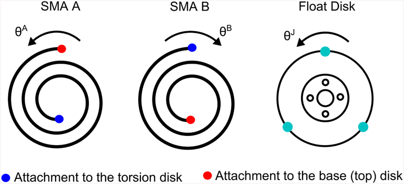
The SMA torsion springs both contain five coils and have identical geometrical and mechanical properties including the same counter-clockwise winding shape. The two SMA torsion springs on the left- and right-side in figure 1(b) are denoted as SMA A and SMA B, respectively. Figure 2 shows the schematic of SMA torsion springs and float disk as a right view of figure 1(b). The positive directions of SMA A and SMA B at their attachment to the torsion disk are counter-clockwise and clockwise and the positive direction of the torsion actuator, as well as the torsion and float disks, is counter-clockwise. So a positive motion of SMA A and a negative motion of SMA B will generate a positive motion of the torsion actuator. Before assembly, both torsion springs are tightened by 0.5θP (θP is the total pre-deformation of the springs) to generate a total pre-deformation of three cycles in our prototype. If SMA A is heated by electrical current, it will generate a recovery torque, move clockwise and deform SMA B via the torsion disk, and vice versa. In this way, the torsion disk and the float disk can rotate bi-directionally when different SMA torsion springs are alternately actuated by Joule heating and natural cooling.
Figure 2.
Schematic of SMA torsion springs and float disk with definitions of positive angle directions.
2.2. SMA Torsion Spring Training
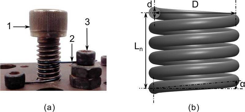
There are two steps for training SMA torsion springs. As shown by figure 3(a), the first step is shaping the SMA torsion spring by winding a nitinol wire around an off-the-shelf metallic bolt mounted on a steel block. The two ends of the nitinol wire are fixed by bolts and nuts. To develop a compact torsion actuator, a small diameter of the torsion spring is preferable, but the coil pitch will decrease if the diameter of the off-the-shelf bolt decreases. Too small a pitch is inappropriate, since the neighbouring coils could contact each other and cause a large friction torque on the actuator. Besides, there is also a trade-off for the diameter of the nitinol wire. An SMA torsion spring made of very thin wire may not generate sufficient torque to move the external load, while a very thick wire will increase the spatial volume of the actuator and the chance of contact amongst neighbouring coils. Thus, based on our group’s prior research on SMA actuators [10], the geometric properties of the SMA torsion spring for this torsion actuator are summarized in table 1.
Figure 3.
(a) Training setup for SMA torsion springs: Fixing bolts and nuts (1), Shaping bolt (2) (thread size is 5/16”–18), and Nitinol wire (3) (diameter is 0.5mm). (b) Schematic of the SMA torsion spring.
Table 1.
Geometric properties of SMA torsion springs.
| Parameter | Meaning | Value | Unit |
|---|---|---|---|
| D0 | Initial Mean Diameter | 6.8 | mm |
| D | Wire Diameter | 0.5 | mm |
| Nc0 | Initial Coil Number | 5 | N/A |
| N0 | Initial Active Coil Number | 3 | N/A |
| p | Coil Pitch | 1.3 | mm |
The second step is heat treatment of the torsion spring. The SMA wire with the metallic block is kept in an oven at 490°C for 40 minutes. After this, this device is taken out of the oven and dipped inside an ice-water mixture to cool it down. After the annealing process, the SMA wire is removed from the metallic block and forms an SMA torsion spring which shows one-way shape memory. When the SMA torsion spring is deformed and then heated, it will tend to recover its original shape and exert a pulling force if its two ends are constrained.
3. Torsion Actuator Modeling
In this section, we conduct an analysis of the shear and normal strains for the torsion spring, demonstrate that the normal strain is the dominant strain in the torsion spring, and derive the constitutive model for the SMA torsion spring based on the normal strain change. We then derive the quasi-static model for the torsion actuator by taking the Coulomb friction torque into account and utilizing the mechanical model of the SMA torsion spring.
3.1. Shear and Normal Strain Analysis
During assembly, the SMA torsion springs are mounted between the disks with a small amount of axial pre-compression. Figure 3(b) shows the schematic of the SMA torsion spring. The natural axial length without any axial constraints is denoted as Ln and given by: Ln = Ls sin α, where Ls is the length of the nitinol wire and α is the pitch angle of the spring coils. If we assume that α is constant when the torsion spring is rotated, Ln does not change either. Thus, the compression of the torsion spring is constantly equal to the pre-compression, which is given by: Lδ = Ln − Lc, where Lc is the distance between the torsion disk and the base (top) disk. The shear strain of the torsion spring is given by [38]:
| (1) |
where d, N, and D are the wire diameter, number of active coils, and spring mean diameter, respectively, and Kw is the Wahl correction factor approximately equal to one[39]. If α is assumed to be small, Ls is given by:
| (2) |
Thus Ls can be calculated by the initial values of N and D, which are denoted as N0 and D0 as shown in table 1. Since the first and last coils of the torsion spring are fixed with the disks and not deformable, N0 is equal to three as shown in table 1. The angle of the torsion spring and the number of its active coils is correlated by:
| (3) |
where θ is the angle of the torsion spring. By substituting equations (2) and (3) into equation (1), the shear strain is rewritten as:
| (4) |
On the other hand, the maximum normal strain in a wire with a circular cross-section is given by:
| (5) |
By substituting equations (2) and (3) into equation (5), the normal strain is rewritten as:
| (6) |
where εi and εi represent the initial strain due to spring shaping and strain change due to torsion, respectively. Due to the annealing process, εi can be subtracted and the above equation is simplified to:
| (7) |
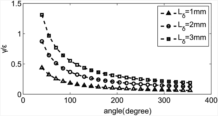
where . The ratio between the shear strain and the normal strain with respect to the torsion angle is shown in figure 4. It shows that for a small amount of pre-compression, the shear strain is much smaller than the normal strain after a rotation of 100°. In our case, Lδ is equal to 0.5mm and the deformation of the SMA torsion spring is assumed to be much larger than 100°, so only the normal strain is modeled for the SMA torsion spring.
Figure 4.
Ratio between the shear strain and the normal strain in terms of torsion angle under different pre-compressions.
3.2. Constitutive Model for SMA Torsion Spring
Most of the SMA constitutive models are based on the assumption of quasi-static loading and thermodynamic equilibrium. Considering the validity of Liang-Rogers model in predicting the behavior of bending joints in our group’s prior work [10] [11], we have adopted the same model. According to the Liang-Rogers model, the one-dimensional SMA constitutive model is given by [34]:
| (8) |
where E, Ω, and Θ represent the Young’s modulus, transformation coefficient and thermal coefficient of expansion, respectively. T, σ, ε, and ξ denote the temperature, stress, strain, and martensite volume fraction, respectively. The variables with subscript ‘0’ denote their initial status. The thermal coefficient is negligible, because the strain caused by thermal expansion is much smaller than the strain caused by phase transformation. When (Note: is the start of the stress-induced martensite phase), the Young’s modulus is given by [34]:
| (9) |
where EA and EM are the Young’s modulus values when ξ is equal to 0 and 1, respectively. When , the Young’s modulus is constant at ES. The phase transformation coefficient is given by [34]:
| (10) |
where εL = C1 θL, as indicated by equation (7), and εL and θL are the maximum recoverable strain and torsion angle, respectively. For a torsion spring, the stress is correlated with torque by [38]:
| (11) |
where , τ is the torque, and Kc is the stress-concentration factor approximately equal to one. By substituting equations (7), (10), and (11) into equation (8), the constitutive model for the SMA torsion spring is given by:
| (12) |
During the transformation from martensite phase to austenite phase (M→A) and from austensite phase to martensite phase (A→M), ξ is given by:
| (13) |
and
| (14) |
where As, Af, Ms, Mf, CA and CM represent the austinite start temperature, austinite finish temperature, martensite start temperature, martensite finish temperature, and stress influence coefficients for these two processes, respectively. Therefore, ten parameters including EA, EM, ES, As, Af, Ms, Mf, CA, CM, and need to be characterized by experiments. Three approaches for transformation temperature determination, including DSC, electrical resistance, and applied loading method, have been examined by Abel et al. [40]. The results showed that the applied loading method was the most effective and the transformation temperatures measured by the electrical resistance method and the applied loading method were similar. Hence, we have adopted the applied loading method to determine these model parameters.
3.3. Mechanical Model for SMA Torsion Spring
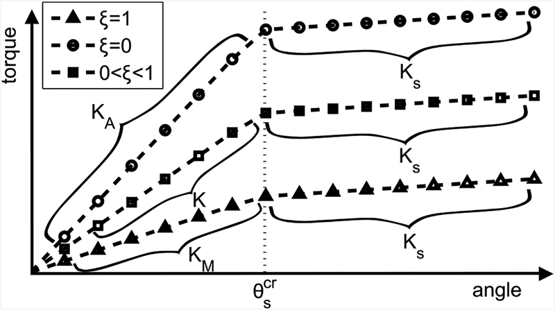
When ξ changes due to temperature variation, the Young’s modulus of SMA changes which results in a change in the stiffness of the SMA torsion spring. Since the Young’s modulus of SMA depends on as discussed in section 3.2, the stiffness of the torsion spring is divided into two sections by the critical angle, , which is given by:
| (15) |
When , the stiffness of the torsion spring is given by:
| (16) |
where
When , the stiffness of the torsion spring is given by:
| (17) |
EA is almost two to three times larger than EM, and ES is much smaller than EM. The stiffness of the SMA torsion spring as a function of the torsion angle is shown in figure 5, which shows that the torsional stiffness is divided into two regions by .
Figure 5.
Schematic of the torsion stiffness of SMA torsion spring for different ξ vs. the angle of SMA torsion spring.
3.4. Quasi-Static Actuator Model
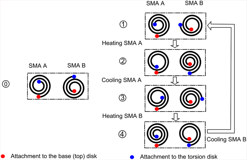
The model of the SMA-actuated torsion actuator comprises of a pair of antagonistic SMA torsion springs, which are denoted as SMA A (2) and SMA B (5) and connected by the torsion disk (3) as shown in figure 1. If we assume that SMA A and SMA B are alternately heated and naturally cooled, figure 6 shows the working mechanism of the SMA-actuated torsion actuator. The red sections represent the fixation parts of spring coils to the base disk and the top disk, and the blue sections represent the fixation parts of spring coils to the torsion disk.
Figure 6.
Working mechanism of the SMA-actuated torsion actuator when SMA A and SMA B are alternately heated and naturally cooled. The cooling process here is natural cooling in ambient air. Status 0 denotes the initial configurations of non-heated SMA A and SMA B.
From status 1 to status 2, SMA A is heated to recover its deformation, resulting in a clockwise rotation of the torsion actuator. After the heating is stopped at status 2, SMA A is naturally cooled to the room temperature from status 2 to status 3. In this process, SMA A is slightly deformed by SMA B due to the reduced stiffness of SMA A, and a counter-clockwise rotation of the actuator is caused. Then, SMA B is heated when SMA A is at the low temperature from status 3 to status 4. If we assume that the heating and cooling processes for SMA A and SMA B are identical, the motion process will return to status 1 after SMA B is cooled naturally to the room temperature. Therefore, our modeling process will focus on the heating and cooling processes for SMA A. The parameters of SMA A and SMA B at specific status are respectively denoted as and (i = 1, 2, 3, 4), where P is a particular physical parameter, such as torsion angle (θ), torque (τ), temperature (T), and martensite volume fraction (ξ). Because of pre-deformation, θP, the torsion angles of SMA torsion springs are correlated by:
| (18) |
where θA and θB are the torsion angles of SMA A and SMA B, respectively, as shown in figure 2. If the torsion actuator moves in a quasi-static way, the torques applied on the torsion disk are statically balanced, which yields:
| (19) |
where τA and τB are torques given by SMA A and SMA B, respectively, and τf is the Coulomb friction torque. It is assumed that when the torsion actuator moves, where τc is the constant friction magnitude and θJ is the angle of the torsion actuator as shown in figure 1. When the torsion actuator is static, the Coulomb friction torque varies between ±τc.
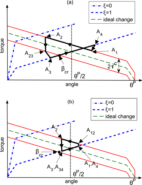
By incorporating the Coulomb friction torque into the stiffness model (figure 5) and utilizing the angle and torque relations given by equations (18) and (19), two typical motion processes are shown in figure 7 by following the working mechanism as shown in figure 6. The boundary condition to differentiate these two cases is whether the SMA torsion spring is heated to an angle smaller than a critical angle βcr. In case (a), the torsion actuator will not move in the beginning of the cooling process due to friction torque until SMA A reaches A23 when τA decreases. When τf = τc, the torsion actuator starts moving counter-clockwise. In the heating process, SMA A will start moving immediately from A3 once it reaches the transformation temperature. In case (b), the torsion actuator will be motionless in the whole cooling process from A2 to A3 due to friction torque. In SMA A heating process, the torsion actuator will not move in the beginning when τA increases, until τf = −τc at A12. We will model the heating and cooling processes for SMA A for these two cases, respectively. In SMA A heating process, the governing equation is given by:
| (20) |
where the initial status is A1 when SMA A starts getting heated. Since in case (b), the torsion actuator will not move until A12, we will study the heating process from A12 to A2 and take A12 as the initial status instead of A1. When the torsion actuator is static from A1 to A12, the governing equation at A12 is given by:
| (21) |
Where
Note that . Equation (21) can be rewritten as a quadratic equation as a function of , and is solved from it. If , it implies that τc = 0 and the torsion actuator will move immediately once SMA A is heated. If or no appropriate solution exists, it implies that the torsion actuator will stay static in the whole heating process, since τc is too large. Therefore, we take for case (a) and for case (b). When the torsion actuator starts moving, the friction torque is constant, so the change of τA is the same as τB, which varies by following the rate of KS. So the change of τA is given by:
| (22) |
By substituting equation (22) into equation (20), the angle of SMA A is given by:
| (23) |
After the heating process, SMA A is naturally cooled down in ambient air. In this process, equation (20) is still the governing equation. In case (a), the torsion actuator will not move until it reaches A23. So we will look into the cooling process from A23 to A3 and take A23 as the initial status instead of A2. From A2 to A23, the change of θA is zero, so the governing equation at A23 is given by:
| (24) |
where
Note that . Equation (24) can be rewritten as a quadratic equation as a function of , and is solved from it. If , it implies that the torsion actuator will be static in the whole cooling process due to relatively large τc. If , it implies that the torsion actuator will move immediately once the cooling process begins because τc = 0. So we take for case (a). After A23, the torsion actuator starts moving and the change of τA is given by:
| (25) |
By substituting equation (25) into equation (20), the angle of SMA A is given by:
| (26) |
The stop angle of SMA A at A3 can be solved using the following torque balance expression:
| (27) |
Where
is solved from the above expression as:
| (28) |
The critical angle βcr can be solved by letting , which yields:
| (29) |
In case (b), the torsion actuator will not move from A2 to A3, so the angles of torsion springs are given by and .
Figure 7.
Schematic of the motion process of torsion actuator when (a) and (b). Ideal change is the torque of SMA torsion spring when it is heated and there is no friction torque, and its upper (lower) solid lines denote the torque of SMA torsion spring when τf is equals to τc and −τc, respectively. The motion process follows the sequence 1→2 → 3→4 →1.
4. Characterization Experiments
This section presents the characterization experiments for the quasi-static model of the SMA-actuated torsion actuator. It comprises of two steps, including characterizations of the SMA torsion spring and the Coulomb friction torque of the torsion actuator.
4.1. SMA Torsion Spring Characterization
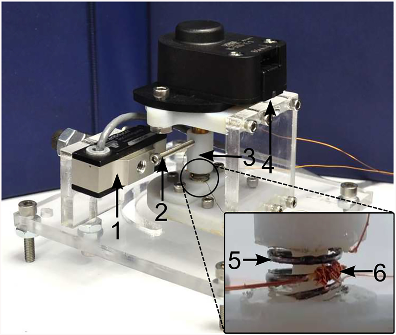
The experimental setup for the torsion spring characterization is shown in figure 8. An SMA torsion spring of four coils is fixed to the base of the platform at its bottom coil. The top coil is fixed to a linker mounted on the shaft of a encoder (US Digital H5–5000-IE-S), and thus the torsion angle can be measured and fed to a master PC. A pair of electrical wires are soldered to the top and bottom coils to realize Joule heating by a current source (Maxon Servoamplifier LSC 30/2). The current output can be controlled by modulating the voltage command given by the master PC. A RTD temperature sensor (Alpha 56A1002-C3) is bonded with the middle section of the torsion spring to measure and feed the temperature to the master PC. All digital and analog signals are communicated via a I/O board (Sensory 626) in the master PC. Based on this setup, there are four steps of the SMA torsion spring characterization as shown in table 2.
Figure 8.
Experimental setup for the SMA torsion spring characterization: Load cell (1), Leverage (2) (Ll = 26.4mm), Linker (3), Encoder (4), SMA torsion spring (5), and RTD Temperature sensor (6).
Table 2.
SMA torsion spring characterization steps.
| Test No. | Test Description | Characterized Parameters |
|---|---|---|
| 1 | Torque Free Test | As, Af |
| 2 | Torsion Angle vs. Force Test | EM, Es, , ϵcr |
| 3 | Heating Process of Block Test | EA, CA |
| 4 | Cooling Process of Block Test | Ms, Mf, CM |
Step 1 - Torque free test:
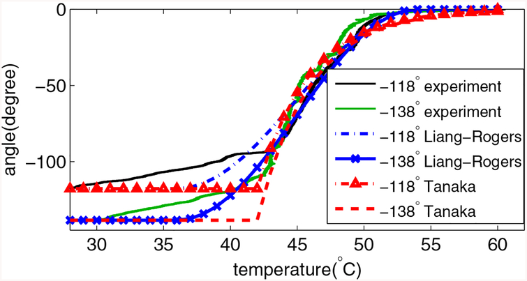
The load cell (Transducer Techniques MLP-10) in figure 8 is removed in this step. The torsion spring is pre-deformed to a particular angle (θd) at the room temperature and it will start recovering to its initial configuration when it is heated above the transformation temperature. If the friction torque is negligible, the recovery angle profile can be derived from equation (12) as: θ = θ0 + θL(ξ − 1), where θ0 and θL are both equal to θd. Figure 9 shows the angle profile when the torsion spring is pre-deformed to −118° and −138°, respectively. The least-square approach is adopted to fit the Liang-Rogers model and the Tanaka’s model with the experimental data by searching for optimal As and Af. The results show that the Liang-Rogers model can fit the experimental results better, so As and Af are summarized in table 3.
Figure 9.
Experimental torsion angle at zero torque level during the heating process along with the model. The root-mean-square error (RMSE) is 9.5752° for Liang-Rogers model (As=36° C,Af=54° C) and 14.8436° for Tanaka’s model (As=42° C,Af=60° C). R2=0.9771 (−118°, Liang-Rogers), R2=0.9860 (−138°, Liang-Rogers), R2=0.9454 (−118°, Tanaka), and R2=0.9653 (−138°, Tanaka).
Table 3.
Results of characterization
| Parameter | Value | Unit |
|---|---|---|
| As | 36 | °C |
| Af | 54 | °C |
| Ms | 53 | °C |
| Mf | 32 | °C |
| EM | 30.035 | GPa |
| EA | 96.375 | GPa |
| ES | 7.847 | GPa |
| CA | 95 | MPa/°C |
| CM | 56 | MPa/°C |
| 0.0046 | N/A | |
| τc | 0.0007 | Nm |
Step 2 - Determination of EM and ES:
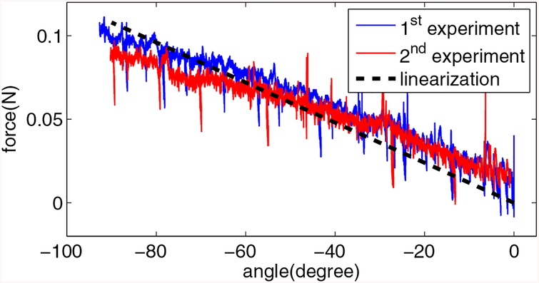
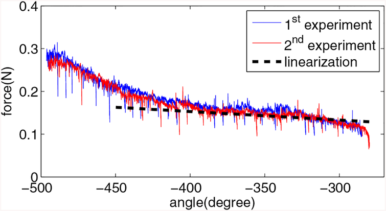
The experimental setup is the same as the first step, except that the bolt works as a lever to apply a pushing force on the load cell. In this step, the relationship between the torsion angle and the pushing force is measured at the room temperature. So when ξ = 1 at the room temperature, the governing equation (12) is rewritten to , where F is the measured force applied on the load cell, and F0 is the initial force when θ is equal to θ0, and Ll is the leverage length. Since the encoder reading is negative when the SMA torsion spring tightens, we have used absolute value of angle difference. By measuring the rate of force change before and after , the values of EM and ES can be obtained. Figures 10 and 11 show the reaction forces of the load cell for these two cases, respectively, and linearization of the experimental data yields the value of EM and ES. In figure 11, we select the middle section of the angle profile (−400° to −300°) to do the linearization, because the stress will initially increase at the rate of EM if the stress starts from zero, and the ending of the stress-induced martensite phase may be achieved in the end of the angle profile. Another reason to explain the increased rate of force change is that the friction torque between the neighbouring coils increases significantly when the coils become very tight at a large torsion angle. The intersection of the linearization results yields the critical angle, , and is found by using equation (15). Experimentally determined values of EM, ES, and are summarized in table 3.
Figure 10.
Reaction force of the load cell vs. the torsion angle for small angle range at the room temperature. The RMSE is 0.0105N. R2-value is 0.8475 for the 1st experiment and 0.7421 for the 2nd experiment.
Figure 11.
Reaction force of the load cell vs. the torsion angle for large angle range at the room temperature. The RMSE is 0.0113N. R2-value is 0.6357 for the 1st experiment (−400° to −300°) and 0.7532 for the 2nd experiment (−400° to −300°).
Step 3 - Determination of EA and CA:
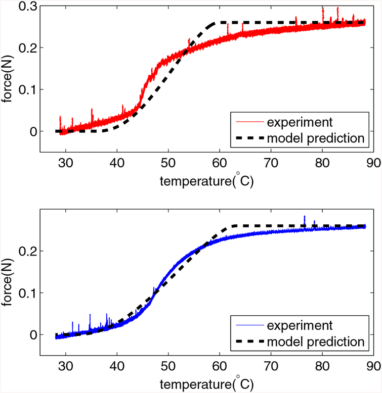
The block test is adopted, and the experimental setup is the same as the second step. In this step, the SMA torsion spring is pre-deformed and the pre-deformation is measured to be −85° in our test. When the torsion spring is heated and tends to recover the deformation, the load cell will constrain its motion and the block force is measured. A PI controller is adopted to track the temperature reference by modulating the current input to the SMA torsion spring with temperature feedback from the RTD temperature sensor. From equation (12), the generated force is given by: , where ξ is described by equation (13), and when ξ = 0, the generated force is maximum and is given by: . Note that we have used absolute value of angle, since the encoder reading is negative when the SMA torsion spring tightens. Thus, EA can be characterized by using the measured maximum force. By using the least-square approach to fit the profile of the generated force, optimal CA value is characterized, and values of EA and CA are summarized in table 3. The experimental results and model predictions are shown in figure 12(a).
Figure 12.
(a) Reaction force of the load cell for the block test when the SMA torsion spring is heated. The RMSE is 0.0227N, and R2-value is 0.9392. (b) Reaction force of the load cell for the block test when the SMA torsion spring is cooled down naturally after the test(a). The RMSE is 0.0125N, and R2-value is 0.9850.
Step 4 - Determination of Ms, Mf and CM for A→ M:
Different from M → A, the shape of the SMA torsion spring will not change when it is cooled down, so the torque free test is not feasible. Thus, we take advantage of the cooling process of the previous block test to characterize Ms, Mf and CM by fitting the model using the least-square approach. In the cooling process, the expression of the generated force is the same as that during the heating process in the previous test, while ξ is described by equation (14). Figure 12(b) shows the experimental results and the model predictions based on the fitted model when the SMA torsion spring is cooled down after the test shown in figure 12(a). The values of Ms, Mf and CM are summarized in table 3.
4.2. Friction Torque Characterization
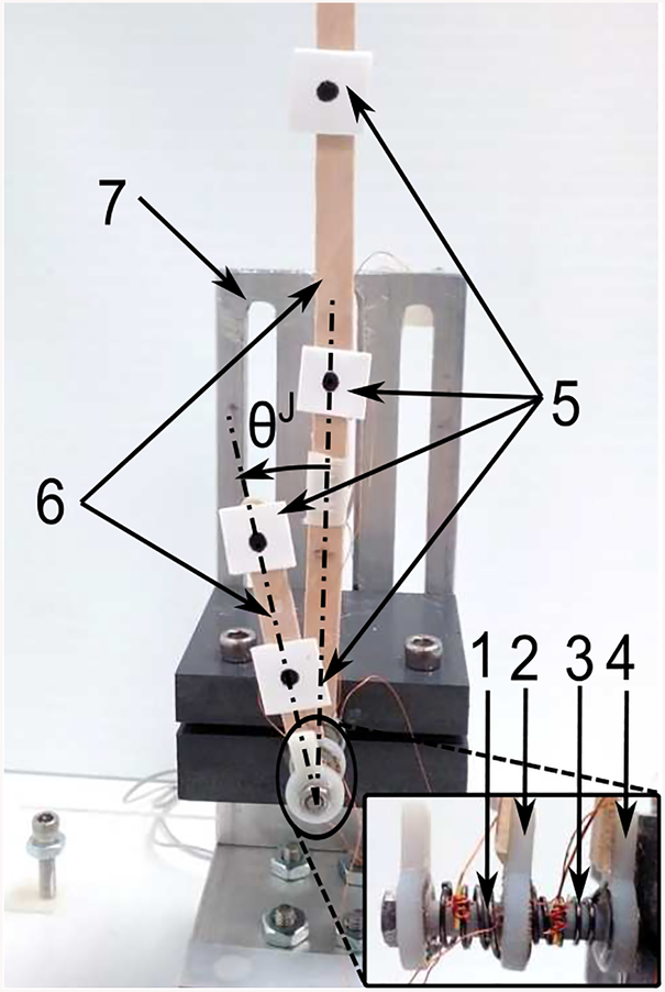
The experimental setup for the Coulomb friction torque characterization is shown in figure 13. The torsion actuator is installed on the test stage by fixing the torsion shaft between two parallel plates mounted on the stage. Two weightless (practically) wooden sticks are respectively glued on the base disk and the torsion disk with two vision markers on either stick. The vision camera (MicronTracker 2) is used to track the four vision markers by Lucas-Kanade optical flow method. The spatial positions of all markers are calculated by OpenCV libraries and the orientations of both sticks are computed by marker positions. Using this approach, the angle of the torsion actuator is obtained by tracking the various markers. All vision-related processes are conducted on a slave PC.
Figure 13.
Experimental setup for the Coulomb friction torque characterization: SMA A (1), Torsion disk (2), SMA B (3), Base disk (4), Markers (5), Wooden sticks (6), and Test stage (7). An RTD temperature sensor is attached to each SMA torsion spring.
The electrical wires of either SMA torsion spring are connected between the current source and a switch (International Rectifier IRL540N MOSFET), which is controlled ON and OFF by the master PC through the I/O board. By turning one switch ON and turning the other switch OFF, we can heat the corresponding SMA torsion spring by passing electrical current and control current magnitude by the voltage command. The temperature of either SMA torsion spring is measured by the RTD temperature sensor, and the measurements are fed to the master PC via the I/O board. The sampling time of the master PC is set as 15ms to coordinate serial communication with the slave PC.
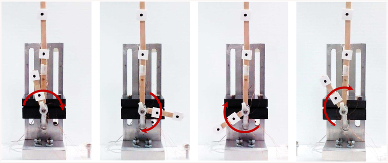
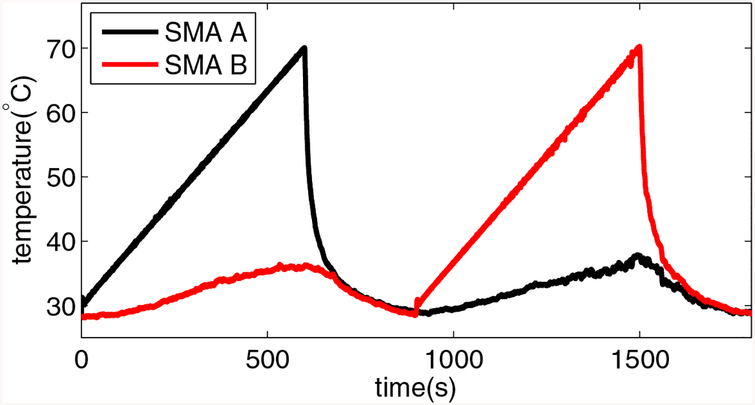
The positive direction of the torsion actuator is counter-clockwise as shown in figure 13. When SMA A is heated, the torsion actuator moves clockwise and the torsion angle decreases, and vice versa when SMA B is heated. To have a uniform home position for the torsion actuator, we heat SMA B to make the actuator rotate to the positive extremum and then cool it down naturally to make it stop at a stable angle. This stable angle is exclusively determined by the properties of the actuator and assumed to be the same for different tests. This characterization experiment includes two consecutive steps. In the first step, the torsion actuator is actuated in the negative direction by heating SMA A for ten minutes according to a temperature reference, as shown in figure 14, followed by a natural cooling process for the subsequent five minutes. In the second step, the torsion actuator is actuated in the positive direction and SMA B is heated and then naturally cooled in the same way. The temperature change in the heating process is controlled by a PI law given by: , where eT = Tr − T, and ir, Tr, T, , and are the current reference, temperature reference, actual temperature, and proportional and integral gain, respectively.
Figure 14.
Snapshots of the torsion actuator characterization experiment. When SMA A is heated, the actuator moves clockwise as the arrow indicates.
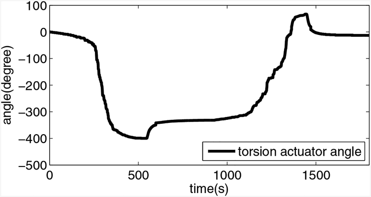
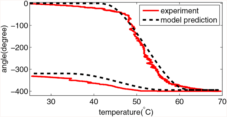
The angle change of the torsion actuator is shown in figure 15. It shows that the maximum motion range is 466°. The heating and cooling processes are slow to ensure a quasi-static motion of the torsion actuator and figure 16 shows the temperature profiles for both SMA torsion springs. It shows that when one SMA torsion spring is heated, the temperature of the other one increases slowly, probably because of the heat transfer between them via the ambient air and the actuator body. From figures 15 and 16, we observe that the angular extremum is achieved when the temperature of SMA torsion spring is close to 70° C. Since the motion of the two steps are theoretically identical due to the same heating and cooling processes, only the heating and cooling process for SMA A is employed here for the Coulomb friction torque characterization. The angle of the torsion actuator as a function of temperature for SMA A is plotted in figure 17. By applying the least-square approach with the quasi-static model, the Coulomb friction torque is characterized and summarized in table 2. As shown in figure 17, the quasi-static model predicts the angle change of the torsion actuator well.
Figure 15.
Evolution of the angle of the torsion joint in one cycle. Because the bi-directional motion is symmetric, the profile is shifted to align the middle angle position with the zero angle.
Figure 16.
Temperature profiles of the SMA torsion springs. The SMA A and SMA B are alternately heated for ten minutes to track pre-designed temperature references and then cooled naturally in ambient air for five minutes to reach the room temperature.
Figure 17.
Angle profile of the torsion actuator when SMA A is heated and then naturally cooled. The root-mean-square error is 16.7588° and R2-value is 0.9867.
5. DISCUSSION AND CONCLUSIONS
The primary contributions of our work includes the following aspects. Firstly, we propose the novel design of a meso-scale SMA-actuated torsion actuator. The mechanical design of the torsion actuator and the fabrication approach of SMA torsion springs are presented. Secondly, we conduct a strain analysis of the torsion spring, followed by the constitutive model for the SMA torsion spring and then derive the quasi-static model for the torsion actuator. Thirdly, a series of experiments are designed and implemented to characterize all model parameters and the Coulomb friction torque. The model prediction based on the characterized parameters fits the experimental result well.
The development of this SMA-actuated meso-scale torsion actuator is the first step towards a disposable SMA-actuated neurosurgical robot for intracerebral hemorrhage evacuation. The fatigue life of SMA materials can be more than one hundred cycles if the frequency is low [41] and over one hundred thousand thermal cycles can be achieved by NiTi-based SMA [42]. Considering the fact that the required speed for a typical neurosurgical hemorrhage evacuation procedure is not high and the number of cycles is usually limited, the stability of the designed actuator is assumed to be high. The maximum block torque of this actuator was measured to be several mNm, which is smaller than the torque output of a bi-directional torsion actuator based on SMA wires in [21] and larger than the torque output of typical PZT torsion actuators [43] [44]. Considering the presented device and the diameter of adopted SMA wires are much smaller compared to [21], the torque output of our device is comparable. Since the brain tissue is very soft and the bending joints made of the same SMA wires are capable of steering inside the gelatin [45], the measured torque output is sufficient for our application.
Our future work will focus on improving the mechanical design to seal the actuator, reduce friction torque, and increase the torque output. We also plan to develop a dynamic controller for more precise tracking and faster response, and improve the performance of this torsion actuator on a meso-scale neurosurgical robot.
ACKNOWLEDEGEMENT
Research reported in this publication was supported by the National Institute of Biomedical Imaging and Bioengineering of the National Institutes of Health under Award Number R21EB018581. The content is solely the responsibility of the authors and does not necessarily represent the official views of the National Institutes of Health.
References
- [1].Jamisola RS, Maciejewski AA, and Roberts RG, “Failure-tolerant path planning for the PA-10 robot operating amongst obstacles,” in Robotics and Automation, 2004. Proceedings. ICRA’04. 2004 IEEE International Conference on, vol. 5 IEEE, 2004, pp. 4995–5000. [Google Scholar]
- [2].Kennedy CW and Desai JP, “Modeling and control of the Mitsubishi PA-10 robot arm harmonic drive system,” Mechatronics, IEEE/ASME Transactions on, vol. 10, no. 3, pp. 263–274, 2005. [Google Scholar]
- [3].Sachdev A, “A constraint-aware motion planning algorithm for robotic folding of clothes,” 2012.
- [4].Hess J, Tipaldi GD, and Burgard W, “Null space optimization for effective coverage of 3D surfaces using redundant manipulators,” in Intelligent Robots and Systems (IROS), 2012 IEEE/RSJ International Conference on. IEEE, 2012, pp. 1923–1928. [Google Scholar]
- [5].Flacco F, De Luca A, and Khatib O, “Motion control of redundant robots under joint constraints: Saturation in the null space,” in Robotics and Automation (ICRA), 2012 IEEE International Conference on. IEEE, 2012, pp. 285–292. [Google Scholar]
- [6].Bischoff R, Kurth J, Schreiber G, Koeppe R, Albu-Schäffer A, Beyer A, Eiberger O, Haddadin S, Stemmer A, Grunwald G et al. , “The KUKA-DLR Lightweight Robot arm - a new reference platform for robotics research and manufacturing,” in Robotics (ISR), 2010 41st international symposium on and 2010 6th German conference on robotics (ROBOTIK). VDE, 2010, pp. 1–8. [Google Scholar]
- [7].Toshiyoshi H and Fujita H, “Electrostatic micro torsion mirrors for an optical switch matrix,” Microelectromechanical Systems, Journal of, vol. 5, no. 4, pp. 231–237, 1996. [Google Scholar]
- [8].Jaecklin V, Linder C, De Rooij N, Moret J-M, and Vuilleumier R, “Line-addressable torsional micromirrors for light modulator arrays,” Sensors and Actuators A: Physical, vol. 41, no. 1, pp. 324–329, 1994. [Google Scholar]
- [9].Hsieh J and Fang W, “A novel microelectrostatic torsional actuator,” Sensors and Actuators A: Physical, vol. 79, no. 1, pp. 64–70, 2000. [Google Scholar]
- [10].Ayvali E, Liang C-P, Ho M, Chen Y, and Desai JP, “Towards a discretely actuated steerable cannula for diagnostic and therapeutic procedures,” The International journal of robotics research, vol. 31, no. 5, pp. 588–603, 2012. [DOI] [PMC free article] [PubMed] [Google Scholar]
- [11].Ayvali E and Desai JP, “Towards a discretely actuated steerable cannula,” in Robotics and Automation (ICRA), 2012 IEEE International Conference on. IEEE, 2012, pp. 1614–1619. [DOI] [PMC free article] [PubMed] [Google Scholar]
- [12].Ho M and Desai JP, “Modeling, characterization and control of antagonistic SMA springs for use in a neurosurgical robot,” in IEEE International Conference on Robotics and Automation, 2013, pp. 2503–2508. [Google Scholar]
- [13].Fuda Y and Yoshida T, “Piezoelectric torsional actuator,” Ferroelectrics, vol. 160, no. 1, pp. 323–330, 1994. [Google Scholar]
- [14].Qi Z, Liang PC, Ting MY, Rang KF, and Hua FZ, “Piezoelectric rotary motor based on active bulk torsional element with grooved helical electrodes,” Mechatronics, IEEE/ASME Transactions on, vol. 17, no. 2, pp. 260–268, 2012. [Google Scholar]
- [15].Bernhard AP and Chopra I, “Analysis of a bending-torsion coupled actuator for a smart rotor with active blade tips,” Smart Materials and Structures, vol. 10, no. 1, p. 35, 2001. [Google Scholar]
- [16].Wei Z, Sandstroröm R, and Miyazaki S, “Shape-memory materials and hybrid composites for smart systems: Part I shape-memory materials,” Journal of Materials Science, vol. 33, no. 15, pp. 3743–3762, 1998. [Google Scholar]
- [17].Wei Z, Sandstrom R, and Miyazaki S, “Shape memory materials and hybrid composites for smart systems: Part II shape-memory hybrid composites,” Journal of Materials Science, vol. 33, no. 15, pp. 3763–3783, 1998. [Google Scholar]
- [18].Sun L, Huang WM, Ding Z, Zhao Y, Wang CC, Purnawali H, and Tang C, “Stimulus-responsive shape memory materials: a review,” Materials & Design, vol. 33, pp. 577–640, 2012. [Google Scholar]
- [19].Gabriel K, Trimmer W, and Walker J, “A micro rotary actuator using shape memory alloys,” Sensors and Actuators, vol. 15, no. 1, pp. 95–102, 1988. [Google Scholar]
- [20].Liang C, Davidson FM, Schetky LM, and Straub FK, “Applications of torsional shape memory alloy actuators for active rotor blade control: opportunities and limitations,” in 1996 Symposium on Smart Structures and Materials. International Society for Optics and Photonics, 1996, pp. 91–100. [Google Scholar]
- [21].Huang W, “Shape memory alloys and their application to actuators for deployable structures,” 1998.
- [22].Prahlad H and Chopra I, “Modeling and experimental characterization of SMA torsional actuators,” Journal of intelligent material systems and structures, vol. 18, no. 1, pp. 29–38, 2007. [Google Scholar]
- [23].Jardine AP, Kudva JN, Martin CA, and Appa K, “Shape memory alloy TiNi actuators for twist control of smart wing designs,” in 1996 Symposium on Smart Structures and Materials. International Society for Optics and Photonics, 1996, pp. 160–165. [Google Scholar]
- [24].Huang W, Pellegrino S, and Bashford D, “Shape memory alloy actuators for deployable structures,” in Spacecraft Structures, Materials and Mechanical Engineering, vol. 386, 1996, p. 53. [Google Scholar]
- [25].Epps JJ and Chopra I, “In-flight tracking of helicopter rotor blades using shape memory alloy actuators,” Smart Materials and Structures, vol. 10, no. 1, p. 104, 2001. [Google Scholar]
- [26].Guo Z, Yu H, and Wee L-B, “Design of a novel compliant differential shape memory alloy actuator,” in Intelligent Robots and Systems (IROS), 2013 IEEE/RSJ International Conference on. IEEE, 2013, pp. 4925–4930. [Google Scholar]
- [27].Song G, “Design and control of a Nitinol wire actuated rotary servo,” Smart materials and Structures, vol. 16, no. 5, p. 1796, 2007. [Google Scholar]
- [28].Lan C-C, Wang J-H, and Fan C-H, “Optimal design of rotary manipulators using shape memory alloy wire actuated flexures,” Sensors and Actuators A: Physical, vol. 153, no. 2, pp. 258–266, 2009. [Google Scholar]
- [29].Yoshida E, Kokaji S, Murata S, Kurokawa H, and Tomita K, “Miniaturized self-reconfigurable system using shape memory alloy,” in Intelligent Robots and Systems, 1999. IROS’99. Proceedings. 1999 IEEE/RSJ International Conference on, vol. 3 IEEE, 1999, pp. 1579–1585. [Google Scholar]
- [30].Yan X, Huang D, and Zhang X, “Note: A novel curvature-driven shape memory alloy torsional actuator,” Review of Scientific Instruments, vol. 85, no. 12, p. 126109, 2014. [DOI] [PubMed] [Google Scholar]
- [31].Liang C and Rogers C, “A multi-dimensional constitutive model for shape memory alloys,” Journal of Engineering Mathematics, vol. 26, no. 3, pp. 429–443, 1992. [Google Scholar]
- [32].Graesser E and Cozzarelli F, “A proposed three-dimensional constitutive model for shape memory alloys,” Journal of Intelligent Material Systems and Structures, vol. 5, no. 1, pp. 78–89, 1994. [Google Scholar]
- [33].Tanaka K, “A thermomechanical sketch of shape memory effect: one-dimensional tensile behavior,” Res Mechanica, vol. 18, pp. 251–263, 1986. [Google Scholar]
- [34].Liang C and Rogers C, “One-dimensional thermomechanical constitutive relations for shape memory materials,” Journal of intelligent material systems and structures, vol. 1, no. 2, pp. 207–234, 1990. [Google Scholar]
- [35].Brinson L, “One-dimensional constitutive behavior of shape memory alloys: thermomechanical derivation with non-constant material functions and redefined martensite internal variable,” Journal of intelligent material systems and structures, vol. 4, no. 2, pp. 229–242, 1993. [Google Scholar]
- [36].Huang W, “Modified shape memory alloy (SMA) model for SMA wire based actuator design,” Journal of Intelligent material systems and structures, vol. 10, no. 3, pp. 221–231, 1999. [Google Scholar]
- [37].Jayender J, Patel RV, Nikumb S, and Ostojic M, “Modeling and control of shape memory alloy actuators,” Control Systems Technology, IEEE Transactions on, vol. 16, no. 2, pp. 279–287, 2008. [Google Scholar]
- [38].Shigley JE and Mischke CR, “Mechanical engineering design,” 2001. [Google Scholar]
- [39].Wahl A, “Mechanical springs, 1963,” McGAWHILL, p119. [Google Scholar]
- [40].Abel E, Luo H, Pridham M, and Slade A, “Issues concerning the measurement of transformation temperatures of NiTi alloys,” Smart materials and structures, vol. 13, no. 5, p. 1110, 2004. [Google Scholar]
- [41].Tobushi H, Nakahara T, Shimeno Y, and Hashimoto T, “Low-cycle fatigue of TiNi shape memory alloy and formulation of fatigue life,” Journal of engineering materials and technology, vol. 122, no. 2, pp. 186–191, 2000. [Google Scholar]
- [42].Huang W, “On the selection of shape memory alloys for actuators,” Materials & design, vol. 23, no. 1, pp. 11–19, 2002. [Google Scholar]
- [43].Kanda T, Makino A, Ono T, Suzumori K, Morita T, and Kurosawa MK, “A micro ultrasonic motor using a micro-machined cylindrical bulk PZT transducer,” Sensors and Actuators A: physical, vol. 127, no. 1, pp. 131–138, 2006. [Google Scholar]
- [44].Flynn AM, “Piezoelectric ultrasonic micromotors,” 1997.
- [45].Ayvali E, Ho M, and Desai JP, “A novel discretely actuated steerable probe for percutaneous procedures,” in Experimental Robotics. Springer, 2014, pp. 115–123. [Google Scholar]


