Abstract
To eliminate tethering effects on the small animals’ behavior during electrophysiology experiments, such as neural interfacing, a robust and wideband wireless data link is needed for communicating with the implanted sensing elements without blind spots. We present a software-defined radio (SDR) based scalable data acquisition system, which can be programmed to provide coverage over standard-sized or customized experimental arenas. The incoming RF signal with the highest power among SDRs is selected in real-time to prevent data loss in the presence of spatial and angular misalignments between the transmitter (Tx) and receiver (Rx) antennas. A 32-channel wireless neural recording system-on-a-chip (SoC), known as WINeRS-8, is embedded in a headstage and transmits digitalized raw neural signals, which are sampled at 25 kHz/ch, at 9 Mbps via on-off keying (OOK) of a 434 MHz RF carrier. Measurement results show that the dual-SDR Rx system reduces the packet loss down to 0.12%, on average, by eliminating the blind spots caused by the moving Tx directionality. The system operation is verified in vivo on a freely behaving rat and compared with a commercial hardwired system.
Keywords: neural interfacing, implantable medical devices, software-defined radio, wireless, electrophysiology
I. Introduction
Studies on popular small animal models, such as rodents, often require a sensing element, attached to or implanted in the animal body [1]-[3]. These early prototypes of future implantable medical devices (IMDs), need to establish a direct communication pathway with external data processing, storage, visualization, and control units, often implemented within a computer. In the case of neural interfacing, for instance, such instruments are expected to be capable of recording from and stimulating the neural tissue for closed-loop neuromodulation [4]. The recorded data from evoked neural activities in this case provide researchers with feedback on the effectiveness of the stimulation and help them optimize the stimulation parameters in a closed-loop fashion by analyzing the neural response [5]. It is well understood that most neural functions arise from a large population of neurons over a large tissue area [6]. Therefore, researches have focused on developing high-density recording and stimulation front-ends that need wide bandwidth [7], [8].
Traditionally, the communication link between sensors and external computing unit lias been established through hardwires, which may cause stress in the animals, biasing their behaviors, in addition to motion artifacts. Hardwires also restrict the study to one subject at a time due to being entangled or other animals housed in the same cage damaging them [9]-[11]. Several wireless neural interfacing systems have been developed to eliminate tethering effects [ 12]-[21 ]. Even though the focus has been mainly on the transmitter (Tx) side, these IMDs, either battery- or wirelessly-powered, require a wireless receiver (Rx), as part of the broader data acquisition system, which also includes other blocks, such as RF front-end, data demodulator, PC interface, digital signal processing, storage, external control, feedback, and graphical user interface (GUI).
There are several challenges in developing such a wireless data acquisition system. One is the wide bandwidth needed to support a large number of simultaneously recorded channels in a high-density interface, which can easily reach tens of Mbps [22]-[24]. In experiments involving freely behaving animals, subjects continuously move across the experimental arena and show natural behaviors, such as sniffing, rearing, and climbing the walls, as shown in Fig. 1, resulting in constant variation in the Tx position and orientation, which result in degradation of the RF signal strength at the position of stationary Rx antenna. Yet another challenge is keeping the Tx size and weight as low as possible to reduce the subject burden in carrying the IMD, as well as the risk of biasing the animal behavior [25]. This would impose a limit on the Tx power consumption in turn, and the size of its antenna, which combined with the other challenges, makes it challenging to maintain wireless data integrity and continuity by preventing blind spots anywhere within the experimental arena [22], [23]. Despite a few attempts with a small number of simultaneously active channels [12]-[14], the abovementioned requirements have ruled out utilization of the most popular commerical off-the-shelf (COTS) solutions, such as Bluetooth low energy (BLE), ZigBee, or Wi-Fi, because of limited bandwidth or high power consumption.
Fig. 1.
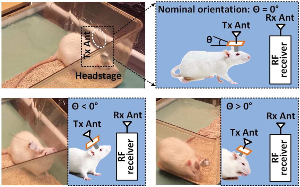
Various conditions for wireless data transmission in the experiments with freely behaving rodents, resulting in misalignment between the Tx and Rx antennas, caused by the movements of animal subject.
The rule of thumb in designing such data acquisition systems is to reduce the complexity and power consumption on the Tx side (IMD), often at the cost of more complexity on the Rx side, which is not under the abovementioned constraints [22], [23]. Several customized systems for wireless neural interfacing have been developed. In [15]-[17], the IMDs have on-chip Tx-Rx, which send recording data via an inductive link with amplitude-shift keying (ASK), on-off keying (OOK), frequency-shift keying (FSK), or phase-shift keying (PSK). In [18] and [19], the on-chip Tx encodes the recording data onto the carrier signal via FSK and OOK, respectively. In [20] and [21], the ultra-wideband (UWB) technique is used to send data out. However, there is not enough information on the wireless coverage of the link and elimination of blind spots. In our prior work [22], we introduced a custom-designed Rx with a dual-antenna structure to extend the wireless coverage over a large experimental arena. Developing and fine-tuning the custom Rx was complicated, and simultaneously operating two of them required manual synchronization, which reduced the system scalability.
To address these limitations, we present a new data acquisition system, which takes advantage of the flexibility, ease of use, and scalability of multiple COTS software-defined radios (SDRs), operating in parallel. The dual-SDR prototype presented here, using the open-source BladeRF x40 hardware platform from Nuand (San Francisco, CA) [26] and GNU Radio software platform [27], not only extends the wireless coverage over the entire volume of an experimental arena, the size of a standard homecage, for freely behaving rodents, but also eliminates the RF blind spots caused by spatial and/or angular positioning of the Tx and Rx antennas to minimize the required Tx radiation power. Because the SDRs operate independently, the proposed system also avoids complex connection and synchronization procedures among them. An overview of the wireless data acquisition system architecture is given in Section II. Section III and IV present benchtop and in vivo results, respectively, followed by discussion and conclusion.
II. System Overview
Fig. 2 shows the conceptual view of the key components of the wireless implantable neural recording and stimulation (WINeRS-8) system for behavioral neuroscience studies on small freely behaving animals. On the Tx side, the WINeRS-8 headstage, which is equipped with a custom-designed wireless 32-ch neural recording and 4-ch neural stimulation system-on-a-cliip (SoC) for closed-loop neuromodulation applications, lias been described in [28]-[30]. The WINeRS-8 headstage is wirelessly-powered within the modified standard-sized rodent homecage, known as the EnerCage-HC2 system, which is described in [31], [32]. Efficient wireless power transmission (WPT) is achieved through a resonance-based 4-coil inductive link to reduce the weight of the headstage while eliminating any limitation on the duration of longitudinal experiments. The EnerCage-HC2 system is also equipped with forward and back data telemetry by on-off-keying the power carrier of the inductive link, in addition to the BLE, as an alternative [28], [29]. The former sends recording configuration and stimulation parameters to the headstage. The latter is adapted for closed-loop power control (CLPC) by sending the supply voltage information of the headstage back to the EnerCage-HC2. The focus of this paper is on a key part of WINeRS-8 system that is not covered in previous publications, the dual-SDR Rx, which is capable of receiving a large amount of digitalized raw data from the custom 434 MHz OOK-modulated RF link and delivering it a PC that is running a custom GUI for data visualization, processing, and storage.
Fig. 2.
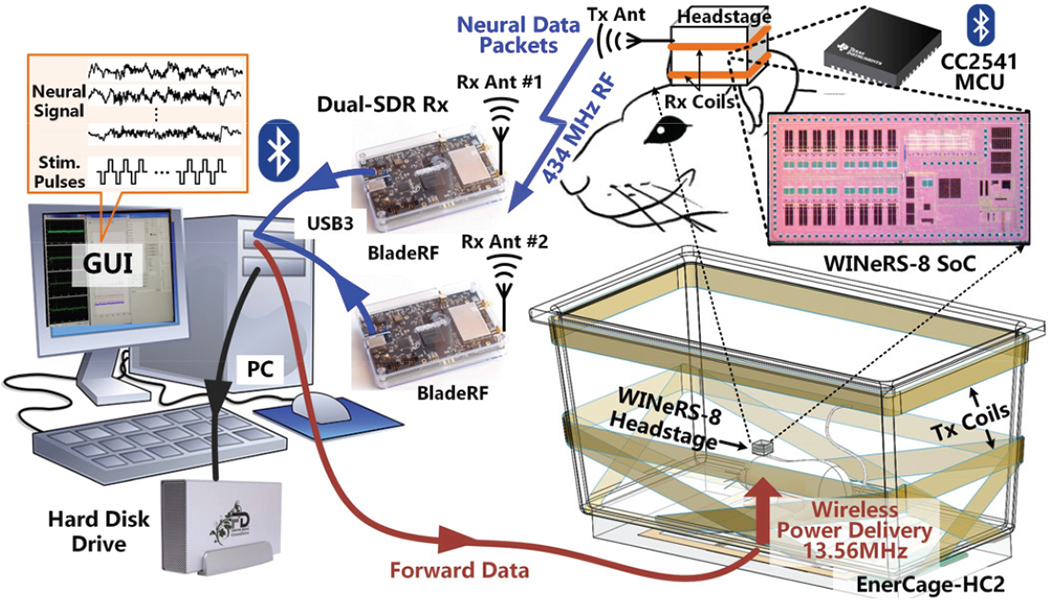
A conceptual representation of the complete WINeRS-8 system with dual-SDR Rx for neural interfacing studies with freely behaving rodents.
Fig. 3 shows the key building blocks of the wideband data telemetry link. WINeRS-8 SoC includes a 32-ch analog front-end (AFE) for neural recording [30]. Every two channels share a 50 kS/s 10-bit successive approximation register (SAR) analog-to-digital converter (ADC). Each digitization cycle generates a 176-bit data packet that is serially delivered to the on-chip Tx, which in turn OOK modulates the 434 MHz RF carrier in a power amplifier (PA), followed by a custom-designed off-chip antenna. The 434 MHz RF signal is picked up outside the homecage by the RF front-ends of two SDRs [26]. The LMS6002D front-end (Lime Microsystems, UK) in each BladeRF SDR Rx digitizes and pre-processes the RF signal before sending it to the GNU radio [27], running on the PC, through their individual USB3 ports, for post-processing. From the two incoming received data streams, the GNU radio picks the one with higher signal strength, and extracts the neural data from data packets before de-multiplexing 32 channels, storing them in the hard disk drive (HDD), and displaying them on the GUI in real-time.
Fig. 3.

Key blocks in the wireless 32-ch neural recording from the WINeRS-8 headstage to the PC, using the proposed wideband dual-SDR Rx.
A. Dual-SDR Rx Design-1
Fig. 4a shows the algorithmic block diagram of the dual-SDR Rx design-I, in which the SDRs are only in charge of receiving and digitizing the RF signal, while most of the digital signal processing (DSP) functions are implemented in the GNU radio within the PC. The GNU radio sets the parameters of the SDR RF front-end, such as gain, bandwidth, center frequency, and sampling rate, through the USB port. The RF signal is received, oversampled by a factor of 4, and converted to 12-bit digitalized I & Q samples in each RF front-end, before being sent to the PC through its dedicated USB3 port. The GNU radio converts the two data streams from SDRs to magnitudes, EIQ1 and EIQ2, and passes them through 2000-point moving average filters to establish the signal strengths, EAvr1 and EAvr2, respectively. In Fig. 4b example, Rxl and Rx2 antennas are aligned at 90° and 0°, respectively, with respect to the Tx antenna at the same distance. As expected, EAvr2 > EAvr1
Fig. 4.
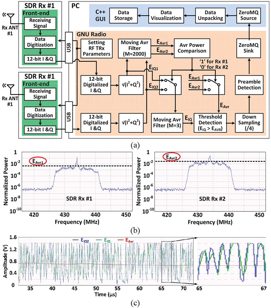
(a) Simplified algorithm architecture of the dual-SDR Rx design-I. (b) Signal strength of the data stream from the SDR Rx #1 and the SDR Rx #2. (c) Operation of the adaptive threshold detection.
Once the stronger signal is determined, in this case, EIQ2 is passed through a wideband 3-point moving average filter for noise reduction, EIQ, and compared with the narrowband signal strength, EAvr2 for OOK demodulation. Since the EIQ baseline and EAvr change together, this operation is the equivalent of adaptive thresholding, as shown in Fig. 4c, which combined with the redundancy provided by dual Rx antennas, ensures robust OOK demodulation and data recovery in the presence of continuous Tx displacements and misalignments due to animal movements within the homecage.
The following block is a 4:1 down-sampling module before searching the data stream for a pre-defined 13-bit preamble (1100101000001), which is selected in a way that minimizes the possibility of the overlaps with the recorded data [33]. The data content following each matched preamble is then extracted from the data stream, and sent to the GUI for unpacking and demultiplexing. The GUI is implemented in C++ via ZeroMQ protocol and extracts the individual 32-ch neural recording data from each data packet. ZeroMQ is a transport layer protocol for exchanging messages between two software platform peers [34]. The GUI code also displays the acquired data in real-time and saves it in the PC HDD. The main advantage of the dual-SDR Rx design-I compared to [22] is the use of simple COTS components, flexibility in software-based design, development, and modifications, offered by GNU radio, and ease of use without the need for manual synchronizations among SDRs. On the other hand, it puts a heavy burden on PC resources, which limits the scalability of this approach.
B. Dual-SDR Rx Design-II
As the number of SDRs increase in an attempt to cover larger experimental arenas, or to facilitate the use of a lower power Tx, it is possible to implement the DSP algorithm front-end within a high-end SDR in a way that the Rx computational resources scale with the number of SDRs. In fact, each BladeRF SDR, as well as many other recent SDRs, is equipped with an Altera Cyclone IV (Santa Clara, CA) field-programmable gate array (FPGA) with 115 k logic elements, which can be utilized for tliis purpose, as shown in Fig. 5.
Fig. 5.
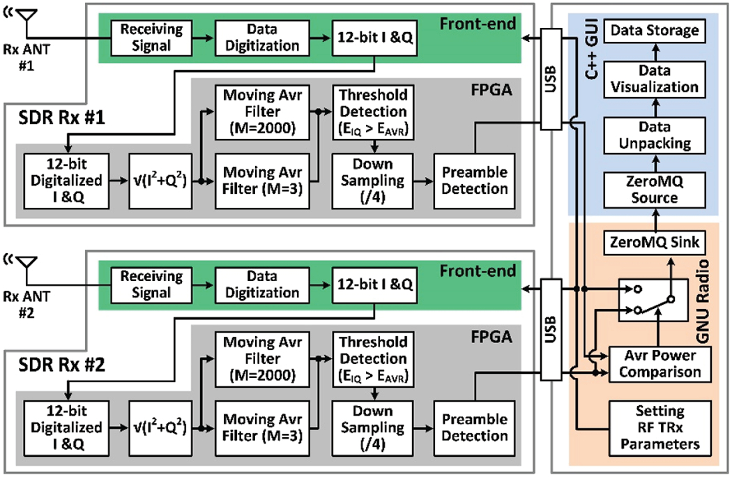
Simplified algorithm architecture of the dual-SDR Rx design-II
In each SDR used in design-II, the received RF signal is oversampled, converted to 12-bit digitalized I & Q samples in the RF front-end, and delivered to the FPGA, which calculates the magnitude of the incoming samples. The FPGA then uses 2000-point and 3-point moving average filters to generate EAvr and EIQ, respectively, for adaptive thresholding. The recovered serial data stream is then down-sampled 4:1 before being searched for preambles. The data packets are then extracted from the data stream and sent to the PC via the USB port. The GNU radio running on the PC carries a much lighter load in this design, comparing the two incoming data streams in terms of their signal strengths, and selecting the stronger one for unpacking, plotting, and data storage by the GUI, which is identical to design-I. Since the PC workload, handled by the GNU radio, requires a small amount of resource, several SDRs can be handled by a PC with nominal specs in this architecture. The SDR in design-II is expected to have sufficient computational resources, often provided by a built-in FPGA.
C. Antenna Design
Since the Rx antennas are fixated outside of the experimental arena such that the animal subject would move only on one side of the antenna, directional antennas are more efficient for this purpose. For the Tx antenna, on the other hand, an omnidirectional antenna is more suitable as the animal moves around the homecage and holds its head in various orientations. Considering these requirements, a planar inverted-F antenna (PIFA) and a monopole antenna were chosen for the Rx and Tx, respectively [35]. Because of the long wavelength of the data carrier at 434 MHz, the quarter-wavelength monopole exceeds the height of the homecage. Therefore, a spiral monopole antenna, built with copper wire, was designed based on the steps introduced in [36].
Fig. 6 shows the 3D models of the Tx and Rx antennas in the CST Microwave Studio (Waltham, MA). The WINeRS-8 headstage includes two printed circuit boards (PCBs), stacked in a 3D printed plastic box, with the Tx antenna connected to the lower PCB. These PCBs are included in the Tx antenna model, as shown in Fig. 6a. The geometry of the Rx antenna has been optimized for it to operate at 434 MHz, as shown in Fig. 6b. The backside of the substrate is used as a ground plane for the Rx antenna, which is placed in the center of the substrate to reduce the coupling effect between the antenna and ground plane [37]. Finally, the Rx antenna shorting pin is placed on the upper-left corner.
Fig. 6.
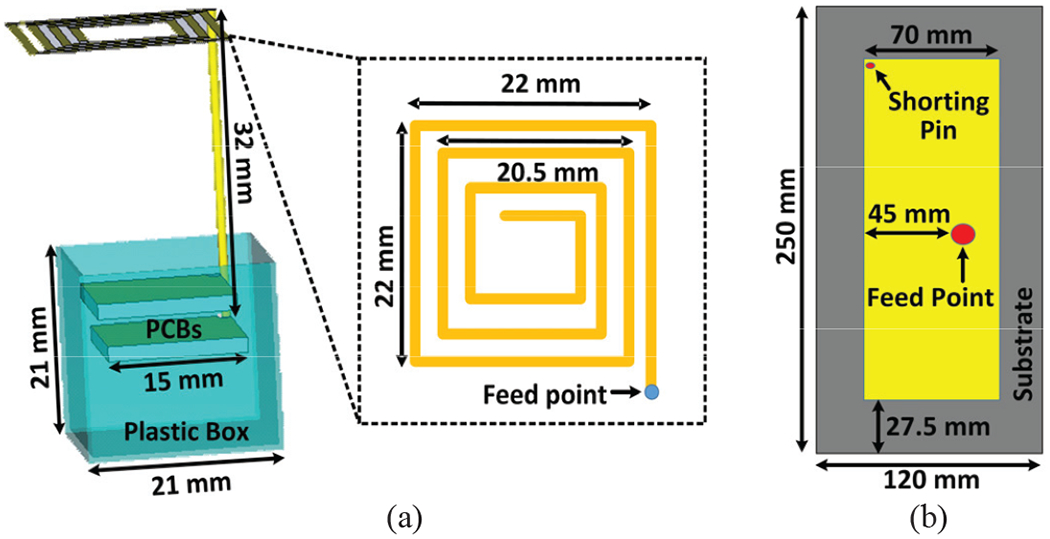
3D simulation models of the (a) Tx antenna and (b) Rx antenna in the CST environment.
III. Experimental Results
A. System Implementation
Fig. 7a shows the WINeRS-8 headstage equipped with the Tx antenna extending from the top. The headstage includes two stacked PCBs, fitting in a 21×21×21 mm3 cube, plus a 4×9×12 mm3 extension at the bottom to provide mechanical supports for an 18-pin Omnetics Nano-strip connector (Minneapolis, MN). The connector is further reinforced with a small magnet, which facilitates mounting the headstage on the animal head. A pair of Rx coils with optimized geometries for maximizing the power transfer efficiency (PTE) of the 4-coil inductive link is wound around the 3D-printed cube [31]. In [28] and [29], the headstage cannot receive sufficient power with >80° headstage rotation, although the CLPC increases the EnerCage-HC2 output power to the highest level. In practice, a temporary storage in the headstage, such as a supercapacitor (PB-5R0V104-R) is added to supply the headstage for up to 25 s when the received power is interrupted. In the current prototype, the headstage with the supercapacitor weighs 5.7 g.
Fig. 7.
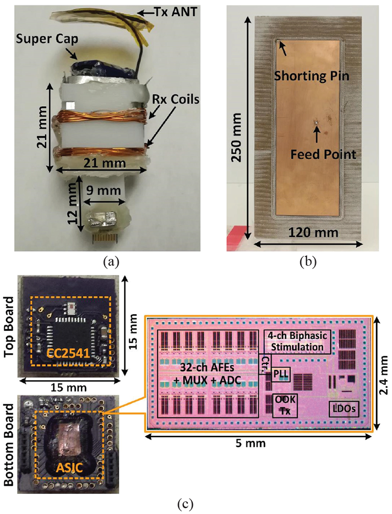
(a) Implementation of the WINeRS-8 headstage with the Tx antenna. (b) Implementation of the Rx antenna. (c) Details of the headstage PCBs and the microphage of the WINeRS-8 ASIC.
Fig. 7b shows the implementation of the Rx antenna, which is fabricated on FR-4 substrate with 1 mm thickness based on the geometry shown in Fig. 6b. Fig. 7c shows the two headstage PCBs, the upper of which includes an AC-DC converter and a CC2541 microcontroller unit (MCU) from Texas Instruments (Dallas, TX). The MCU has a built-in BLE transceiver that can be used for forward data telemetry [32]. The lower board includes the WINeRS-8 SoC and its associated off-chip components. WINeRS-8 SoC was fabricated in a 130-mn standard CMOS process, occupying 2.4×5 mm2 including pads. The MCU receives user-defined parameters from the PC through its BLE link in order to configure the WINeRS-8 SoC, especially for the 4-ch electrical stimulation function, as well as the 32-ch AFE and on-chip Tx that includes a PA, which output power is 5-bit adjustable from −3~0.2 dBm.
B. Antenna Characterization
Figs. 8a and 8b show the measured return loss, S11, of the Tx and Rx antennas, respectively. Both antennas show sufficiently low power reflections of −11.8 dB and −17.7 dB at 434 MHz with bandwidths of 6.5 MHz and 12 MHz at 10 dB return loss, respectively. The measured gain radiation patterns of the Tx and Rx antennas are shown in Figs. 8c and 8d, respectively. The antenna under test (AUT) is mounted at the center of a rotating plate. An E-shape patch antenna, with a calibrated gain of 6 dBi and relatively large bandwidth, is placed 1 m away from the AUT. Both antennas are connected to a vector network analyzer (VNA), which transmits power through the AUT at 0 dBm. The AUT is then rotated 10° at a time, while the transmission coefficient, S21, between the two antennas is recorded for a complete 360° rotation. This measurement was conducted in an anechoic chamber to eliminate multi-path effects. The AUT gain is calculated according to the Friis transmission equation [38], resulting in the realized gain radiation pattern shown in Figs. 8c and 8d. As expected, the Tx antenna shows an omnidirectional radiation pattern with the gain in the range of −6 ~ −8.5 dBi, while the Rx antenna shows a directional pattern with most of the power radiated in front of the antenna at the peak of −0.15 dBi.
Fig. 8.
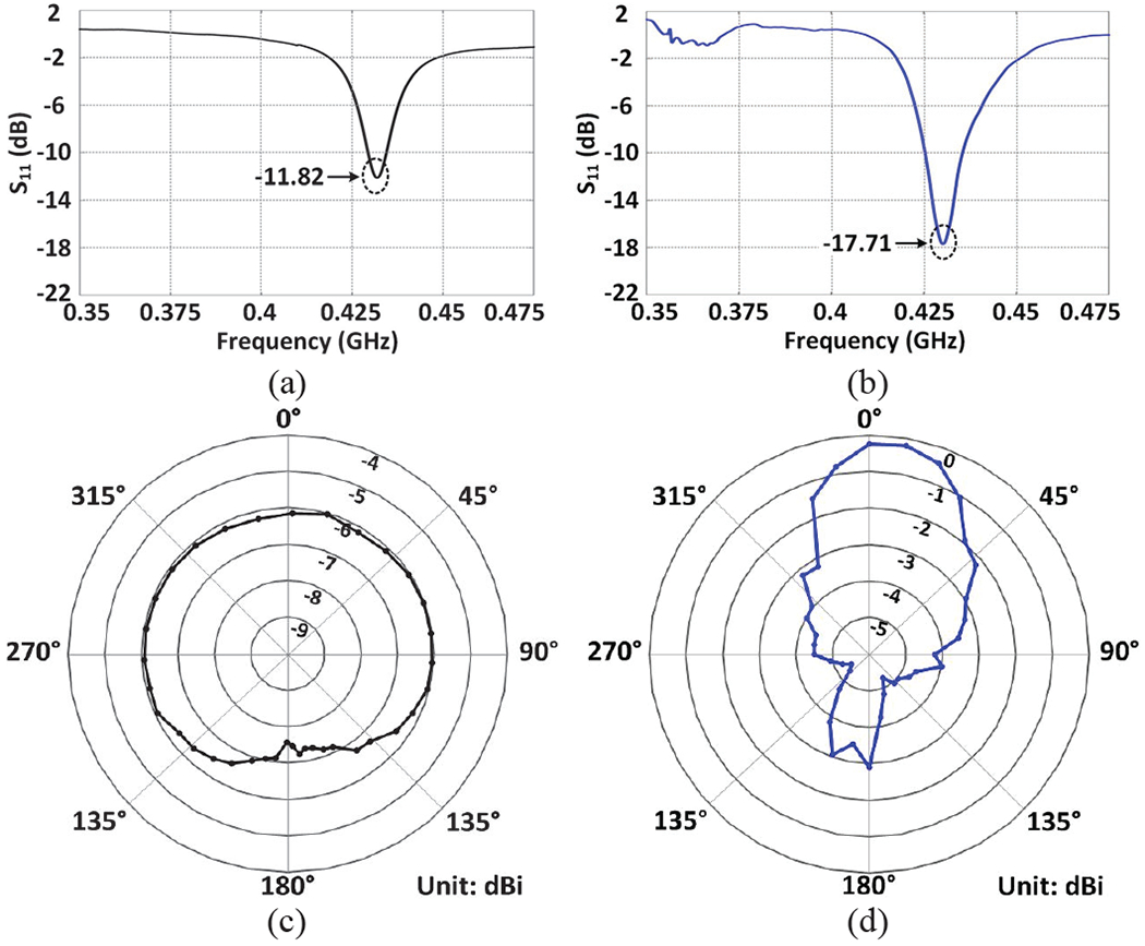
S11 measurement results of the (a) Tx and (b) Rx antennas. Measurement results of the realized gain radiation pattern of the (c) Tx and (d) Rx antennas.
C. System Characterization
The WINeRS-8 headstage was mounted on a small rotating apparatus at the height of 8 cm in the center of the homecage, which is the nominal height of a rat. Two Rx antennas were placed at 1 m distance from the headstage, facing two adjacent sides at 90°. A pre-recorded neural signal is applied to channel #1 of the AFE with −20 dB attenuation. The headstage then amplifies and digitalizes the input signal and sends out the digitalized data packets, which are picked up and recovered by two SDRs. The following measurement results are obtained by analyzing the recovered data.
We manually rotated the headstage along the z and x axes from 0° to 360° with 10° increments to measure the relative radiation pattern of the Tx-Rx antennas against angular misalignments. In each case, data with higher EAvr is chosen by the Rx, and the signal strength was registered and plotted in Fig. 9. Fig. 9a compares the relative radiation patterns with a single-SDR Rx vs. a dual-SDR Rx against the horizontal rotation of the Tx antenna, while Fig. 9b shows a similar comparison against Tx vertical rotation. The results show that because of the Tx omnidirectional radiation pattern, evident from Fig. 8c, dual-SDR Rx performance may not be significantly different from a single-SDR Rx with respect to a horizontal rotation. However, relative radiation with a single-SDR Rx can be as much as 15 dBi less than a dual-SDR Rx with vertical rotations, which can maintain EAvr almost constant even under worst-case conditions. This is because with two vertically oriented Rx antennas and the redundancy built-into the dual-SDR Rx architecture, although the Tx antenna could have a worst-case misalignment with one of the Rx antennas, it still maintains sufficient S21 with the other Rx antenna. Therefore, the dual-SDR Rx removes the RF blind spots, where a single-SDR Rx cannot maintain proper data connectivity due to weak S21.
Fig. 9.
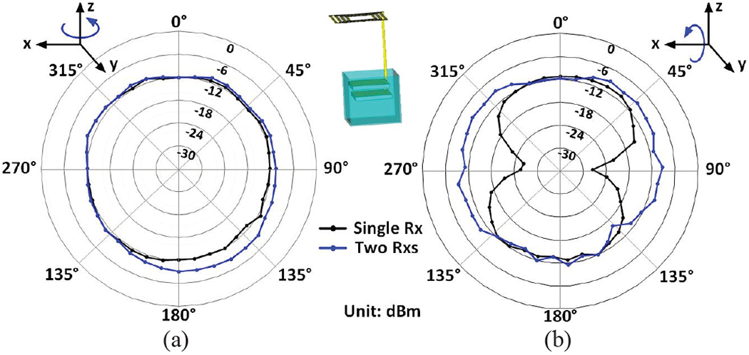
Measured relative radiation pattern with a single-SDR Rx vs. a dual-SDR Rx against (a) the horizontal rotation and (b) the vertical rotation of the Tx antenna.
To characterize the noise performance of the entire WINeRS-8 system under wireless powering condition, the AFE was configured for bandwidth of 20 Hz to 15 kHz and gain of 51.5 dB [30], and powered at 13.56 MHz by the EnerCage-HC2 system, while the Tx-Rx distance was swept from 10 cm to 150 cm with the Rx of design-II. In each case, recovered data is collected when the AFE inputs are shorted to a common node [28], [29]. We applied fast Fourier transform (FFT) to 3-minute periods of recovered data in MATLAB to derive the noise power spectral density (PSD) and referred them back to the AFE input. Fig. 10a shows the input-referred noise PSD at the nominal Tx-Rx distance of 30 cm. Applying square root of the integral under the curve from 10 Hz to 17 kHz yields a root mean square (RMS) noise voltage of 4.68 μVrms for the entire system. Fig. 10b shows the input-referred noise, with the error bar (95% confidence interval) applied to measurements from 5 samples, at various Tx-Rx distances. As the Tx-Rx separation increases, the input-referred noise voltage significantly increases, because the signal strength on the Rx side drops quadratically, according to the Friis transmission equation [38].
Fig. 10.
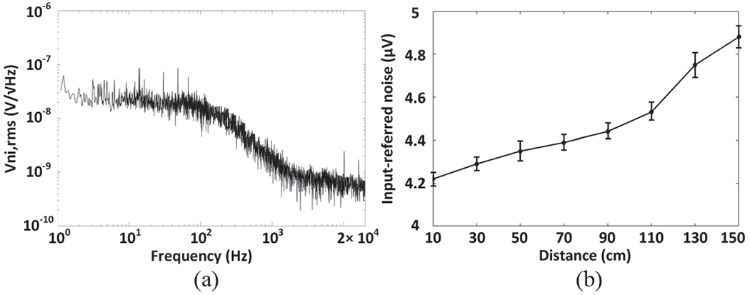
(a) Input-referred power spectral noise density. (b) Input-referred noise versus Tx-Rx distance.
We also measured the dynamic range of the entire system to evaluate its linearity at Tx-Rx separation of 30 cm. A 1 m VPP sinusoidal waveform at 100 Hz was applied to channel #1 of the AFE. The recovered data on the Rx side over 3 minutes was transferred to the frequency domain via FFT to derive its power spectrum. The result in Fig. 11 shows a spurious-free dynamic range (SFDR) of 58.9 dB, which is the equivalent of 7.9 effective number of bits (ENoB) with the signal-to-noise ratio (SNR) of 49.2 dB [39].
Fig. 11.
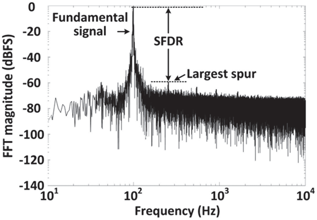
Power spectrum of the recovered data for dynamic range measurement.
Fig. 12 shows the measured rate of packet loss in 5 samples in each case. Each data packet is assigned a 1-bit packet-counter, from which the rate of packet loss can be derived in real-time. Fig. 12a presents the rate of packet loss as a result of changing the Tx-Rx distance from 10 cm to 150 cm using the dual-SDR Rx. As expected, when Tx-Rx separation increases, EAvr decreases, resulting in a higher rate of packet loss. We also compared the rate of packet loss between a single-SDR Rx and a dual-SDR Rx vs. the Tx vertical misalignment in Fig. 12b at 30 cm Tx-Rx separation. Using a dual-SDR Rx, the packet loss is significantly reduced, particularly at sharper misalignments thanks to the relatively stable signal strength of the two orthogonal Rx antennas against angular misalignment (see Fig. 9b). As angular misalignment approaches 90°, the rate of packet loss increases even in dual-SDR Rx. Because the EnerCage-HC2 transmitted power also increases by the CLPC to compensate for the reduction in the received power and keep the headstage functional [32], resulting in stronger electromagnetic (EM) interference with the 434 MHz data link.
Fig. 12.
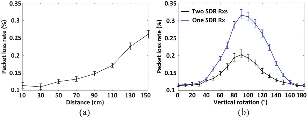
(a) Packet loss vs. Tx-Rx distance with dual-SDR Rx. (b) Comparison between packet loss of a single-SDR Rx and a dual-SDR Rx vs. vertical rotation of the headstage (Tx antenna) at 30 cm Tx-Rx separation.
Emulating a real recording, a pre-recorded neural signal containing spikes in tens of μ VPP range plus a 4 Hz sinewave, representing LFP in the background was applied to channel #1 of the AFE. WINeRS-8 AFE was set to filter out the LFPs and extract the spikes. Fig. 13 shows a short 30 ms interval of the pre-recorded neural signal that was applied to channel #1 (upper trace) and the recovered data on the Rx side (lower trace). It can be seen that the spike is separated from the LFP by high-pass filtering, and can be recovered with high fidelity, which demonstrates the functionality of the dual-SDR Rx system in vitro. Table I summarizes specifications of the dual-SDR Rx prototype as part of the WINeRS-8 system, shown in Fig. 2.
Fig. 13.
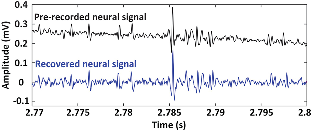
Recovered neural signal at 30 cm Tx-Rx separation compared to the pre-recorded neural signal applied to channel #1 of the WINeR-8 AFE.
Table I.
Specifications of the Dual-SDR Rx as part of the WINeRS-8 System
| WINeRS-8 Headstage | |
| Headstage size | 2.1×2.1×2.1 cm3 |
| Headstage weight | 5.7 g |
| Power consumption | 18.9 mW (ASIC) + 16.1 mW (BLE) |
| Data rate | 9 Mbps |
| Tx output power | −3~0.2 dBm, 5 bits |
| Recording gain | 51.6-76 dB, 3 bits |
| Low cut-off frequency | 20-400 Hz, 3 bits |
| High cut-off frequency | 15 kHz |
| Tx and Rx Antenna | |
| Center frequency | 434 MHz |
| Data modulation type | OOK |
| Tx antenna gain | −6 dBi |
| Tx antenna bandwidth | 6.5 MHz |
| Rx antenna gain | −0.15 dBi |
| Rx antenna bandwidth | 12 MHz |
| Tx-Rx separation | 10-150 cm, 30 cm (nominal distance) |
| SDR Rx (Nuand BladeRF) | |
| SDR Rx gain | 41 dB |
| SDR Rx bandwidth | 18 MHz |
| Sampling rate | 36 MHz |
| Input-referred noise | 4.22-4.88 μVni,rms (10-150 cm distance) |
| Dynamic range | 59 dB (30 cm distance) |
| Packet loss rate | 0.115%-0.2619 6 (10-150 cm distance) |
| 0.114%-0.202% (0°-180° rotation) | |
| PC & FPGA | |
| PC computational resources | Dell Inspiron 3650, 16 GB RAM |
| Intel core i7-6700 CPU @ 3.4 GHz | |
| CPU utilization rate | 80% (design-I), 30% (design-II) |
| FPGA utilization rate | 0% (design-I), 45% (design-II) |
IV. In Vivo Experiments
In vivo experiments were conducted with prior approval from the Institutional Animal Care and Use Committee (IACUC) at Emory University to verity the functionality of the dual-SDR Rx system on the freely behaving rat model. A Sprague Dawley rat was implanted with a 16-ch microelectrode array from Tucker Davis Technologies (Alachua, FL). Two rows of eight tungsten microwire electrodes with a diameter of 50 μm, electrode spacing of 250 μm, and row separation of 500 μm, customized with longer and shorter lengths, targeted the rat hippocampus [40]. The electrodes were approximately placed at 3.5 mm and 2.5 mm ventral from the pia for simultaneous recording from both CA1 (short) and CA3 (long) regions, respectively, as shown in Fig. 14a. The reference and ground wires were wrapped around the cranial screws, before sealing the surgical opening with dental acrylic.
Fig. 14.
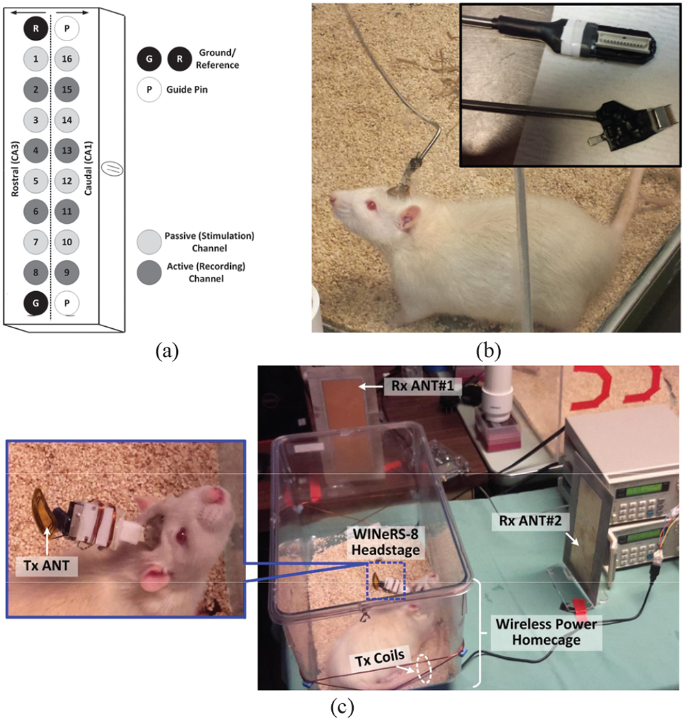
(a) Configuration of the electrodes within the microelectrode array. In vivo experimental setup for the (b) hardwire recording using RZ2 Bio Amp from Tucker-Davis, and (c) WINeRS-8 system, shown in Fig. 2.
After the surgery, the rat was given pain medication and antibiotics to minimize discomfort and prevent infection until it recovered from the surgery and was able to freely move in the homecage. To evaluate the system performance, we compared the recorded neural signal by a commerical hardwired system, RZ2 BioAmp from Tucker-Davis [41], shown in Fig. 14b, and the complete WINeRS-8 system (Fig. 14c). In the latter case, the rat freely moves in the homecage with no tethers, while carrying the WINeRS-8 headstage. The EnerCage-HC2 continuously delivers 35 mW to the headstage with no interruption. Even though the transmitted power from the EnerCage-HC2 increases up to 2.5 W when the headstage is rotated by 90°, magnetic flux density does not surpass the specific absorption rate (SAR) limit at 13.56 MHz [32]. It should be noted that even though in this experiment, only 8 channels were used for neural recording, the data rate did not change, because all 32 channels were still being recorded.
Both hardwired and wireless recorded data were bandpass filtered between 20 Hz and 200 Hz in MATLAB to extract the LFP from the selected electrodes in the CA1 and CA3 regions. Then the wireless recorded data can be fairly compared with the hardwired data. Figs. 15a and 15b show the hardwired and wireless LFP signals, recorded over 4 s, respectively. In Fig. 15a, electrodes #9, 11, 13, and 15 record from the CA1 region, while electrodes #2, 4, 6, and 8 record from the CA3 region. The signals from CA3 were highly correlated and typically showed larger variations. One possible reason for the larger LFP amplitude in CA3 region was the shape of the custom-designed electrode array with different lengths to target both CA1 and CA3 based on the anatomy of the hippocampus. In practice, however, since the relative distance between the electrodes was fixed, once we aimed for recording from CA3, the CA1 electrodes did not end up perfectly within the cell layer. This likely resulted in the lower amplitude recording in the CA1 array. Since the main objective was to compare the hardwired vs. wirelessly recorded data, the results were still viable by observing the same attributes in the wireless and hardwired recordings.
Fig. 15.
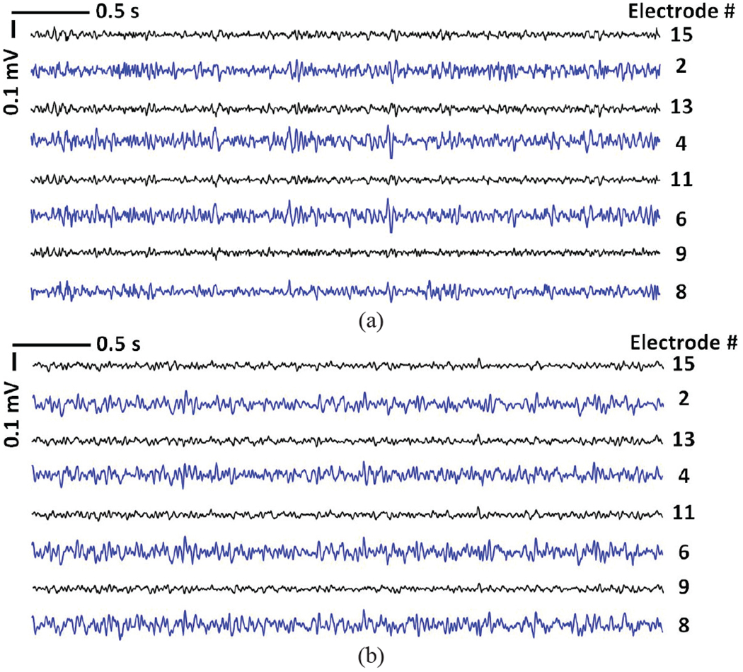
Examples of 4 s long LFP signals recorded back to back from the same rat by the (a) hardwired setup in Fig. 14b, and (b) WINeRS-8 wireless setup in Fig. 14c.
LFP signals from selected electrodes were mapped onto a spectrogram of normalized PSD over a 5-minute window. In Figs. 16a and 16b, the LFP signals recorded from electrode #2 in the CA3 region, measured by the hardwire recording system and the WINeRS-8 system, show higher PSD within a relatively narrow 20~50 Hz band, as compared to the PSD of the LFP signals recorded from electrode #15 in the CA1 region in same frequency band. In short, the LFP signals recorded using commercial hardwired setup and the WINeRS-8 wireless setup show similar features, which demonstrate the functionality of the proposed WINeRS-8 system.
Fig. 16.
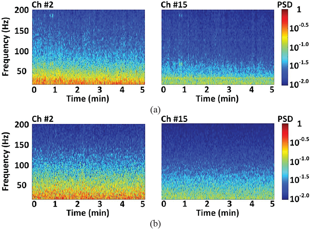
Spectrogram of the normalized LFP recorded from selected CA3 (left) and CA1 (right) electrodes, Ch #2 and Ch#15, using the (a) hardwire recording system shown in Fig. 14b, and (b) WINeRS-8 system shown in Fig. 14c.
V. Discussion
Table II compares WINeRS-8 system with a few recent data acquisition systems in the literature. In [12] and [13], battery-powered headstages for wireless neural recording and optical stimulation are presented, which use 2.4 GHz COTS transceiver (TRx) to send data at 32 kbps and 1.4 Mbps to PC, respectively. In these headstages, if the batteries are selected too small, the uninterrupted duration of the experiment would be too short, particularly in high power or high channel-count applications. On the other hand, if the batteries are selected too high capacity, their weight and size may interfere with animal behavior.
Table II.
Benchmarking of the Data Acquisition Systems for Wireless Neural Recording
| Parameter | [12] 2018 |
[13] 2017 |
[14] 2017 |
[16] 2016 |
[17] 2017 |
[21] 2016 |
[22] 2013 |
This work |
|---|---|---|---|---|---|---|---|---|
| Back telemetry | 2.4 GHz | 2.4 GHz | 2.4 GHz | LSK | LSK | UWB/UWB/FSK | 434 MHz | 434 MHz |
| COTS TRx | COTS TRx | COTS TRx | /Bluetooth | /Wi-Fi | Custom | Custom | ||
| Data Tx power | 21.3 mW | 24.5 mW | 13 mW | 27 μW/17 mW | NA/NA | 0.1/0.1/3.7 mW | 3.3 mW | 4.9 mW |
| # of recording | 2 | 32 | 1 | 16 | 16 | 64 | 32 | 32 |
| Data/sampling rate | 32 kbps | 1.4 Mbps | 2.5 kSps | 20 kSps/ch | 2 Mbps | 45/10/1.2 Mbps | 5.12 Mbps | 9 Mbps |
| Rate of packet loss | 0.3% | NA | NA | NA | NA | NA | NA | <0.261% |
| Data Tx-Rx distance | 3 m | NA | 60 cm | Up to 1 cm | NA | 0.1/1/10 m | Up to 4.2 m | 10 cm-1.5 m |
| Power link | Battery | Battery | Cavity Resonator |
Inductive link |
Inductive link |
Inductive link |
Inductive link |
Inductive link |
| Backpack | No | No | No | Yes | Yes | No | No | No |
| Animal freely behave | Yes | No | Yes | Yes | Yes | NA | Yes | Yes |
| In vivo arena (cm3) | 61×61×16 | NA | 61×61×30 | NA | NA | 45×26 | d=91.4 cm | 24×42×20 |
Wirelessly-powered devices would not face such limitations. In [14], an IMD is wirelessly powered in an arena to send digitalized ECG data at a sampling rate of 2.5 kHz using a COTS 2.4 GHz TRx. The number of channels and bandwidth, however, are low for most neuroscience applications. In [16] and [17], back telemetry via load shift keying (LSK) through a transcutaneous inductive link is adopted to send the recorded data to an external relay in the form of a battery-powered backpack, which wirelessly powers and communicates with the IMD. Even though such elegant solutions impose less limitation compared to hardwired setups [9]-[11], the uninterrupted duration of the experiment would still be dependent on the size of the battery embedded in the backpack. In [21], the system using UWB TRx realizes a high data rate over the desired range. However, the robustness of the system against misalignments and possible blind spots have not been discussed.
Compared to the abovementioned systems, the dual-SDR Rx presented here offers: 1) robust wireless data recovery against spatial and angular misalignments, 2) scalability in terms of the number SDRs operated in parallel in design-II, extending the wireless coverage to the larger arenas, 3) easy implementation and rapid development using software-defined functions either in the FPGA of the SDR or GNU Radio compared to the custom-designed Rx solutions, such as [22], and 4) reasonable workload on the PC, eliminating the need for costly high-end systems. We have demonstrated functionality and robustness of the complete WINeRS-8 system and its compatibility with the EnerCage-HC2 system both in vitro and in vivo. The proposed system can also be utilized for experiments involving non-human primates (NHP), which are often housed in larger cages [42], [43]. Nonetheless, the computer does not have infinite computational resources, causing limitation on the maximum number of SDRs and consequently the maximum wireless coverage. The output power of the RF Tx in the headstage, the gain of the Tx and Rx antennas, and the gain of the SDR Rx are among the other factors affect the maximum wireless coverage area. In addition, the proposed system can support simultaneous recordings from multiple animal subjects with minor modifications. Each headstage can be programmed to have its own unique address to avoid data packet collision. Another method is to allocate each headstage a different band for communication so that they can operate simultaneously without limiting each other’s data rates or bandwidths.
Currently, the data packet is accepted for further processing only when the pre-defined 13-bit preamble is matched, which means even a single bit error occurred in the preamble will cause the entire data packet to be lost. In the future, we intend to add well-known paradigms, such as even-odd parity and cyclic redundancy check (CRC) to find and correct individual data bit errors to further reduce the rate of packet loss. Fig. 12a shows the limits of how far the Rx antenna can be placed from the homecage. As a rule of thumb, the Rx antennas should be placed as close as possible to the rodent homecage. For the head orientation-based increase in the packet loss, shown in Fig. 12b, which is the result of strong power carrier interference, a possible solution would be implementing a new CLPC algorithm that would wait for the supercapacitor to supply the headstage when the received power is not sufficient for keeping the headstage functional and only kick in when it is absolutely necessary. The Tx antenna deformation also influences the data connectivity. The solution would be redesigning the Tx antenna by either increasing the frequency of the data carrier to fit inside the headstage enclosure, or using more robust conductive material, such as carbon fiber to resist deformation.
For the current in vivo experiments, we were facing two limitations. On one end, the SoC, which is mainly designed for recording action potentials, covers an adjustable bandwidth of 20 Hz-15 kHz, and on the other end, we had to adopt a setup that was already available in our collaborators’ lab for LFP signals (0.5 Hz-200 Hz) from the hippocampus region. Therefore, for a fair comparison between the new wireless and existing hardwired setups, we took the overlap, and filtered the acquired raw data from 20-200 Hz. In the future, we intend to design and conduct new dedicated in vivo experiments that compare action potentials. We also intend to enable closed-loop neuromodulation with real-time processing of the recorded raw data using the embedded FPGA in each SDR Rx.
VI. Conclusion
We have presented a scalable dual-SDR Rx system for wideband and robust wireless data acquisition as part of the WINeRS system to eliminate the tethering effect in traditional wired systems. The current prototype can achieve a data rate of 9 Mbps with WINeRS-8 headstage via OOK of a 434 MHz RF carrier, while the headstage is wirelessly powered in the EnerCage-HC2 at 13.56 MHz. Measurement results show that the dual-SDR Rx system can eliminate RF blind spots with the redundancy offered by two orthogonal directional Rx antennas. The presented system overcomes the inflexibility of custom hardware implementation without imposing too much workload on the back-end computing resources in real-time operation. The functionality of the system has been verified both in vitro and in vivo on a freely behaving rat model in comparison with a commercial hardwire system as the gold standard.
Acknowledgments
This work is supported in part by NSF awards ECCS-1407880 and ECCS-1408318, NIH award 1R21EB018561, and NC State University.
Contributor Information
Yaoyao Jia, Department of Electrical and Computer Engineering, NC State University, Raleigh, NC, USA.
Byunghun Lee, Department of Electrical Engineering, Incheon National University, Incheon, South Korea.
Fanpeng Kong, School of Electrical and Computer Engineering, Georgia Institute of Technology, Atlanta, GA, USA..
Zhaoping Zeng, Lixin University, Shanghai, China.
Mark Connolly, Department of Physiology, Emory University, Atlanta, GA, USA.
Babak Mahmoudi, Department of Physiology, Emory University, Atlanta, GA, USA.
Maysam Ghovanloo, Bionic Sciences Inc., Atlanta, GA, USA.
References
- [1].Grill WM, Norman SE, and Bellamkonda RV, “Implanted neural interfaces: biochallenges and engineered solutions,” Annual review of biomedical engineering, vol. 11, pp. 1–24, August 2009. [DOI] [PubMed] [Google Scholar]
- [2].Grone BP, and Baraban SC, “.Animal models in epilepsy research: legacies and new directions,” Nature Neuroscience, vol. 18, pp. 339–343, February 2015. [DOI] [PubMed] [Google Scholar]
- [3].Donoghue JP, “Bridging the brain to the world: a perspective on neural interface systems,”Neuron, vol. 60, pp. 511–521, November 2008. [DOI] [PubMed] [Google Scholar]
- [4].Greenwald E, Masters MR, and Thakor NV, “Implantable neurotechnologies: bidirectional neural interfaces-applications and VLSI circuit implementations,” Med. Biol. Eng. Comput, vol. 54, no. 1, pp. 1–17, January 2016. [DOI] [PMC free article] [PubMed] [Google Scholar]
- [5].Maharbiz MM, Muller R, Alon E, Rabaey JM, and Carmena JM, “Reliable next-generation cortical interfaces for chronic brain-machine interfaces and neuroscience,” Proceedings of the IEEE, vol. 105, no. 1, pp. 73–82, January 2017. [Google Scholar]
- [6].Cong P, “Neural interfaces for implantable medical devices: circuit design considerations for sensing, stimulation, and safety,” IEEE Solid-State Circuits Mag, vol. 8, no. 4, pp. 48–56, November 2016. [Google Scholar]
- [7].Lopez CM, et al. , “A neural probe with pp to 966 Electrodes and up to 384 configurable channels in 0.13 μm SOI CMOS,”IEEE Trans. Biomed. Circuits Syst, vol. 11, no. 3, pp. 510–522, June 2017. [DOI] [PubMed] [Google Scholar]
- [8].Park S, Cho J, Na K, and Yoon E, “Modular 128-Channel Δ-ΔΣ analog front-end architecture using spectrum equalization scheme for 1024-channel 3-D neural recording microsystems,” IEEE J. Solid-State Circuits, vol. 53, no. 2, pp. 501–514, February 2018. [Google Scholar]
- [9].Wang J, Wagner F, Borton DA, Zhang J, Ozden I, Burwell RD, Nurmikko AV, Wagenen R, Diester I, and Deisseroth K, “Integrated device for combined optical neuromodulation and electrical recording for chronic in vivo applications,” J. Neural Eng, vol. 13, no. 3, p. 039501, May 2016. [DOI] [PubMed] [Google Scholar]
- [10].Chen CH, McCullagh EA, Pun SH, Mak PU, Vai MI, Mak PI, Klug A, and Lei TC, “An integrated circuit for simultaneous extracellular electrophysiology recording and optogenetic neural manipulation,” IEEE Trans. Biomed. Eng, vol. 64, no. 3, pp. 557–568, March 2017. [DOI] [PMC free article] [PubMed] [Google Scholar]
- [11].Shulyzki R, Abdelhalim K, Bagheri A, Salam MT, Florez CM, Velazquez JLP, Carlen PL, and Genov R, “320-channel active probe for high-resolution neuromonitoring and responsive neurostimulation,” IEEE Trans. Biomed. Circuits Syst, vol. 9, no. 1, pp. 34–49, February 2015. [DOI] [PubMed] [Google Scholar]
- [12].Jia Y, Khan W, Lee B, Fan B, Madi F, Weber A, Li W, and Ghovanloo M, “Wireless opto-electro neural interface for experiments with small freely behaving animals,” J. Neural Eng, vol. 15, no. 4, p. 046032, June 2018. [DOI] [PMC free article] [PubMed] [Google Scholar]
- [13].Gagnon-Turcotte G, LeChasseur Y, Bories C, Messaddeq Y, Koninck YD, and Gosselin B, “A wireless headstage for combined optogenetics and multichannel electrophysiological recording,” IEEE Trans. Biomed. Circuits Syst, vol. 11, no. 1, pp. 1–14, February 2017. [DOI] [PubMed] [Google Scholar]
- [14].Mei H, Thackston KA, Bercich RA, Jefferys JGR, and Irazoqui PP, “Cavity resonator wireless power transfer system for freely moving animal experiments,” IEEE Trans. Biomed. Eng, vol. 64, no. 4, pp. 775–785, April 2017. [DOI] [PubMed] [Google Scholar]
- [15].Lin Y, et al. , “A battery-less, implantable neuro-electronic interface for studying the mechanisms of deep brain stimulation in rat models,” IEEE Trans. Biomed. Circuits Syst, vol. 10, no. 1, pp. 98–112, February 2016. [DOI] [PubMed] [Google Scholar]
- [16].Liu X, Zhang M, Xiong T, Richardson AG, Lucas TH, Chin PS, Etienne-Cummings R, Tran TD, and Spiegel JV, “A fully integrated wireless compressed sensing neural signal acquisition system for chronic recording and brain machine interface,” IEEE Trans. Biomed. Circuits Syst, vol. 10, no. 4, pp. 874–883, August 2016. [DOI] [PubMed] [Google Scholar]
- [17].Lo Y, Kuan Y, Culaclii S, Kim B, Wang P, Chang C, Massachi JA, Zhu M, Chen K, Gad P, Edgerton VR, and Liu W, “A fully integrated wireless SoC for motor function recovery after spinal cord injury,” IEEE Trans. Biomed. Circuits Syst, vol. 11, no. 3, pp. 497–509, June 2017. [DOI] [PMC free article] [PubMed] [Google Scholar]
- [18].Borna A and Najafi K, “A low power light weight wireless multichannel microsystem for reliable neural recording,” IEEE J. Solid-State Circuits, vol. 49, no. 2, pp. 439–451, February 2014. [Google Scholar]
- [19].Rhew H, Jeong J, Fredenburg JA, Dodani S, Patil PG and Flynn MP, “A fully self-contained logarithmic closed-loop deep brain stimulation SoC with wireless telemetry and wireless power management,” IEEE J. Solid-State Circuits, vol. 49, no. 10, pp. 2213–2227, October 2014. [Google Scholar]
- [20].Brenna S, Padovan F, Neviani A, Bevilacqua A, Bonfanti A, and Lacaita AL, “A 64-channel 965-μW neural recording SoC with UWB wireless transmission in 130-nm CMOS,” IEEE Trans. Circuits Syst. II, vol. 63, no. 6, pp. 528–532, June 2016. [Google Scholar]
- [21].Kassiri H, Bagheri A, Soltani N, Abdelhalim K, Jafari HM, Salam MT, Velazquez JLP, and Genov R, “Battery-less tri-band-radio neuro-monitor and responsive neurostimulator for diagnostics and treatment of neurological disorders,” IEEE J. Solid-State Circuits, vol. 51, no. 5, pp. 1274–1289, May 2016. [Google Scholar]
- [22].Lee SB, Yin M, Manns JR, and Ghovanloo M, “A wideband dual-antenna receiver for wireless recording from animals behaving in large arenas,” IEEE Trans. Biomed. Eng, vol. 60, no. 7, pp. 1993–2004, July 2013. [DOI] [PMC free article] [PubMed] [Google Scholar]
- [23].Lee B, Jia Y, Kong F, Connolly M, Mahmoudi B, and Ghovanloo M, “Toward a robust multi-antenna receiver for wireless recording from freely-behaving animals,” IEEE Biomed. Circuits Syst. Conf. (BioCAS), Cleveland, Ohio, USA, October 2018. [Google Scholar]
- [24].Wu T, Zhao W, Guo H, Lim HH, and Yang Z, “A streaming PCA VLSI chip for neural data compression,” IEEE Trans. Biomed. Circuits Syst, vol. 11, no. 6, pp. 1290–1302, December 2017. [DOI] [PubMed] [Google Scholar]
- [25].Jow UM, McMenamin P, Kiani M, Manns JR, Ghovanloo M, “EnerCage: a smart experimental arena with scalable architecture for behavioral experiments,” IEEE Trans. Biomed. Eng, vol. 61, no. 1, pp. 139–148, January 2014. [DOI] [PMC free article] [PubMed] [Google Scholar]
- [26].BladeRF X40, Nuand, San Francisco, CA, August 2018. [Online]. Available: https://www.nuand.com/product/bladerf-x40/. [Google Scholar]
- [27].GNURadio: Learn About GNU Radio, October 2018. [Online]. Available: http://gnuradio.org.
- [28].Lee B, Koripalli MK, Jia Y, Acosta J, Sendi M, Choi Y, and Ghovanloo M, “An implantable peripheral nerve recording and stimulation system for experiments on freely moving animal subjects,” Scientific Reports, vol. 8, no. 1, p. 6115, April 2018. [DOI] [PMC free article] [PubMed] [Google Scholar]
- [29].Lee B, Jia Y, Mirbozorgi SA, Connolly M, Tong X, Zeng Z, Mahmoudi B, and Ghovanloo M, “An inductively powered wireless neural recording and stimulation system for freely-behaving animals,” IEEE Trans. Biomed. Circuits Syst, January 2019. [DOI] [PMC free article] [PubMed] [Google Scholar]
- [30].Lee B and Ghovanloo M, “An adaptive averaging low noise front-end for central and peripheral nerve recording,” IEEE Trans. Cir. and Syst. II, vol. 65, no. 7, pp. 839–843, July 2018. [DOI] [PMC free article] [PubMed] [Google Scholar]
- [31].Mirbozorgi SA, Jia Y, Canales D, and Ghovanloo M, “A wirelessly-powered homecage with segmented copper foils and closed-loop power control,” IEEE Trans. Biomed. Circuits Syst, vol. 10, no. 5, pp. 979–989, October 2016. [DOI] [PMC free article] [PubMed] [Google Scholar]
- [32].Jia Y, Mirbozorgi SA, Wang Z, Hsu CC, Madsen TE, Rainnie D, and Ghovanloo M “Position and orientation insensitive wireless power transmission for EnerCage-Homecage system,” IEEE Trans. Biomed. Eng, vol.64, no. 10, pp. 2439–2449, October 2017. [DOI] [PMC free article] [PubMed] [Google Scholar]
- [33].MathWorks, PN Sequence Generator, September 2018. [Online]. Available: https://www.mathworks.com/help/comm/ref/pnsequencegenerator.html.
- [34].GNU Radio Manual and C++ API Reference: ZeroMQ, August 2011. [Online]. Available: https://www.gnuradio.org/doc/doxygen/page_zeromq.html.
- [35].Milligan TA, Modern Antenna Design, 2nd ed Piscataway NJ, IEEE press; 2005. [Google Scholar]
- [36].Elsheakh DN, Elsadek HA, Abdallah EA, Iskander MF, and Elhenawy H, “Ultrawide bandwidth umbrella-shaped microstrip monopole antenna using spiral artificial magnetic conductor (SAMC),” IEEE Antennas Wirel. Propag. Lett, vol. 8, pp. 1255–1258, November 2009. [Google Scholar]
- [37].Kong F, Qi C, Lee H, Durgin GD, and Ghovanloo M, “.Antennas for intraoral tongue drive system at 2.4 GHz: design, characterization, and comparison,” IEEE Trans. Microw. Theory Tech, vol. 66, no. 55, pp. 2546–2555. [Google Scholar]
- [38].Balanis CA, Antenna Theory: Analysis and Design, 3rd ed Hoboken, NJ, USA: Wiley, 2016. [Google Scholar]
- [39].Baker RJ, Circuit Design, Layout, and Simulation, 4th ed Hoboken, NJ, USA: Wiley, 2010. [Google Scholar]
- [40].Omnetics Based Electrodes, Tucker-Davis Technologies, Alachua, FL, January 2018. [Online]. Available: https://www.tdt.com/omnetics-based-electrodes.html. [Google Scholar]
- [41].RZ2 BioAmp Processor, Tucker-Davis Technologies, Alachua, FL, January 2018. [Online]. Available: https://www.tdt.com/rz2-bioamp-processor.html. [Google Scholar]
- [42].Yin M, Borton DA, Komar J, Agha N, Lu Y, Li H, Laurens J, Lang Y, Li Q, Bull C, Larson L, Rosler D, Bezard E, Courtine G, and Nurmikko AV, “Wireless neurosensor for full-spectrum electrophysiology recordings during free behavior,” Neuron, vol. 84, no. 6, pp. 1170–1182, December 2014. [DOI] [PubMed] [Google Scholar]
- [43].Tseng P, Rajangam S, Lehew G, Lebedev MA, Nicolelis MAL, “Interbrain cortical synchronization encodes multiple aspects of social interactions in monkey pairs,” Scientific Reports, vol. 8, no. 1, p. 4699, March 2018. [DOI] [PMC free article] [PubMed] [Google Scholar]


