Abstract.
We present a multispectral fundus camera that performs fast imaging of the ocular posterior pole in the visible and near-infrared (400 to 1300 nm) wavelengths through 15 spectral bands, using a flashlight source made of light-emitting diodes, and CMOS and InGaAs cameras. We investigate the potential of this system for visualizing occult and overlapping structures of the retina in the unexplored wavelength range beyond 900 nm, in which radiation can penetrate deeper into the tissue. Reflectance values at each pixel are also retrieved from the acquired images in the analyzed spectral range. The available spectroscopic information and the visualization of retinal structures, specifically the choroidal vasculature and drusen-induced retinal pigment epithelium degeneration, which are hardly visible in conventional color fundus images, underline the clinical potential of this system as a new tool for ophthalmic diagnosis.
Keywords: multispectral imaging, fundus camera, retina
1. Introduction
Optical imaging systems for noninvasive ocular diagnosis remain crucial to assist ophthalmologists in their daily clinical practice. To promptly diagnose ocular and systemic diseases that manifest early in the retina,1–4 efforts have focused on the acquisition of good-quality fundus images. Commercial fundus cameras widely used in the clinical setting include digital cameras that produce color images, with only three spectral bands (R, G, and B). As a result, some retinal structures and substances with different spectral signatures associated with specific ocular diseases5,6 may go undetected due to metamerism or limited spectral range. The capability of identifying these spectral absorption properties in-vivo is key to clinical diagnosis and treatment. Multispectral imaging (MSI) technology, which increases the amount of extractable spectral information from biological tissues using more than three spectral bands, has been used in the last few years to advance the diagnosis of many diseases.7–10 Newly developed fundus cameras that include MSI hold great promise for the analysis of the retina, since they combine the usefulness of spectroscopy with imaging, thus providing both spectral and spatial information of retinal landmarks. For instance, they can spotlight vascular occlusions, vein hemorrhages, drusen, and exudates, and also build oxygenation maps of the retinal vasculature, contributing in this way to the early diagnosis and treatment of conditions such as age-related macular degeneration (AMD) and diabetic retinopathy.11–16
However, most MSI-based retinographs consist of modified traditional fundus cameras whose original illumination or detection systems have been replaced by tunable filters11,17 or light-emitting diodes (LED),12,18 or alternatively, by sequential MSI sensors.19 They are in effect scanning-based systems susceptible to generating severe motion artifacts and pixel misregistration, because the eye is constantly moving; for this reason, some of them only include a few bands. To bypass these issues, snapshot MSI retinal cameras have been put forward for functional retinal mapping.13–15 However, these approaches are limited by maximum resolutions of , which is insufficient to observe the smallest retinal structures for clinical purposes. Additionally, they present extensive computational cost.20 Lastly, most MSI fundus cameras reported to date are limited to the analysis in the visible (VIS) range, ultimately limiting the physician’s ability to detect, discriminate, and further investigate diseases as they develop; only one of them performs measurements up to 850 nm.12
In this report, we present a customized MSI fundus camera that overcomes these limitations, being able to perform fast imaging of the retina in both the VIS and near-infrared (NIR) regions (400 to 1300 nm), through a considerable number of spectral bands (15) and with great spatial resolution. The unexplored range from 900 to 1400 nm, often called second NIR window, is of current interest for biologists21 since it corresponds to the wavelengths in which radiation can penetrate deeper into the tissue (longer wavelengths are highly and less absorbed by water and melanin, respectively), thus providing information about occult or overlapping structures and diseases affecting the retinal pigment epithelium (RPE) and the choroid.
2. Methods and Materials
2.1. Description of the System
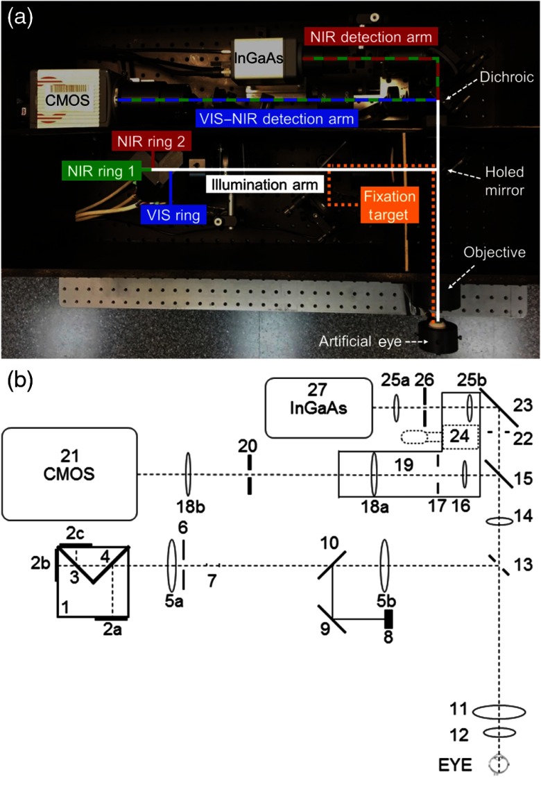
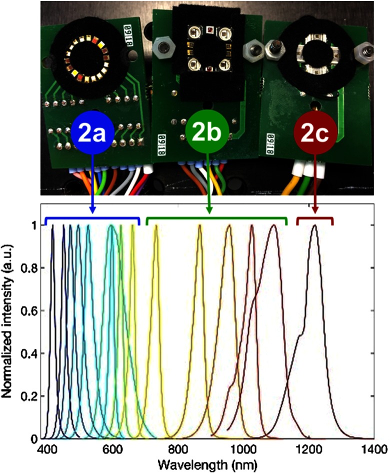
The developed MSI fundus camera was designed using the Zemax optical simulation software (Radiant Zemax LLC). Customized illumination and detection strategies were conceptualized to achieve, through the whole working wavelength range, the best light collection efficiency, aberration balance and cost (only commercial optical components were used), the most uniform field of illumination over the retina, and the minimal presence of ghost images. The resulting system (Fig. 1) has two detection arms: one for the spectral range from 400 to 950 nm (VIS–NIR detection arm) and another for 960 to 1300 nm (NIR detection arm). Both arms share the objective lens, placed in front of the patient’s eye. Regarding the illumination arm, custom-made rings of LEDs were used rather than the most traditional approach of common fundus cameras, where a mask is inserted in the optical path to create a continuous illumination ring on the pupil. Specifically, 32 surface-mount device LEDs were welded in a ring-shaped configuration on three printed circuits board, each responsible for the illumination in a narrowband (Figs. 1 and 2): the VIS ring (2a), with 18 LEDs (9 twin pairs arranged symmetrically) emitting from 400 to 700 nm; the NIR ring 1 (2b), with 10 LEDs (5 twin pairs) emitting from 700 to 1100 nm; and the NIR ring 2 (2c), with 4 LEDs with a peak wavelength of 1213 nm. The former 15 LED clusters have peak wavelengths of 416, 450, 471, 494, 524, 595, 598, 624, 660, 732, 865, 955, 1025, 1096, and 1213 nm. The light from the rings, attached to a custom-made aluminum structure (1), is then combined in a common optical path by means of two dichroic mirrors with cutoff wavelengths at 1150 nm (3) and 700 nm (4).
Fig. 1.
(a) View of the multispectral fundus camera. (b) Optical scheme. Illumination arm: (1) LED rings structure; (2a), (2b), (2c) LED rings; (3), (4) 1150- and 700-nm dichroic mirrors; (5a), (5b) illumination telescopes’ lenses; (6) retinal conjugated diaphragm; (7) antibackreflections stops; (8) fixation target; (9) mirror; (10) beam splitter plate. Detection arms: (11), (12) objective’s lenses; (13) holed mirror; (14) lens; (15) 950-nm dichroic mirror. VIS–NIR detection path: (16) lens; (17) field diaphragm; (18a), (18b) VIS–NIR telescope’s lenses; (19) refraction correction translator platform; (20) aperture diaphragm; (21) CMOS camera. NIR detection path: (22) field diaphragm; (23) mirror; (24) platform-linear translator; (25a), (25b) NIR telescope’s lenses; (26) aperture diaphragm; (27) InGaAs camera.
Fig. 2.
Picture of the LED rings and normalized intensity.
After some lenses, mirrors and stops that prevent the back reflected light from the optical surfaces entering inside the detection optical path (5 to 7), a 45-deg custom-made holed mirror (13) conjugated with the patient’s pupil plane couples the illumination (reflected) and detection (transmitted through the mirror’s central hole) paths. This configuration assesses the geometrical pupil separation required to avoid ghost images caused by reflections (from the cornea and lens) of the illumination in the acquired fundus images. Finally, the LED rings are imaged by the objective lens (11 and 12). A properly designed set of lenses (14, 16, and 18 in the VIS–NIR; 14 and 25 in the NIR) is placed in the detection paths after the holed mirror in order to image the retina in the two cameras (21 and 27), and to compensate for the patients’ spherical refraction (range: ± 15 D) (19). The split of the VIS–NIR and the NIR detection paths is achieved with a dichroic mirror (15) with a cutoff wavelength of 950 nm. Field (17 and 22) and aperture (20 and 26) diaphragms are also used. The camera sensors are a CMOS detector (Orca Flash 4.0, Hamamatsu, Japan), with and 16-bit depth, and an InGaAs camera (C12741-03, Hamamatsu, Japan), with and 14-bit depth, for the VIS–NIR and NIR detection arms, respectively. Finally, a fixation target (8) is placed at a retinal conjugate plane in the illumination arm to achieve adequate patient fixation while performing measurements. All the optical components of the system were carefully selected so that their working spectral range matched the working spectral range of the arm they are part of, in order to minimize the undesired reflections and maximize the transmittance. In particular, some components, such as the objective lens elements, must work for both the VIS and NIR ranges. In those cases, components with a broadband antireflection coating were chosen, ensuring a reflectance of between 400 and 1000 nm according to the manufacturer’s specifications (Edmund Optics Inc). For longer wavelengths, this reflectance tends to increase (4%), although it did not affect significantly the overall performance of the system.
LEDs and cameras are synchronized by means of trigger signals in the electronics, allowing the sequential recording of the whole set of 15 spectral images in 612 ms [264 ms for the CMOS (VIS–NIR) and 348 ms for the InGaAs (NIR)], thus avoiding the imaging problems caused by eye movements. A user-friendly MATLAB interface was developed to control the system’s operation and to set the parameters.
The resulting MSI prototype, built in accordance with ISO standards for ophthalmic instruments and fundus cameras (ISO 15004-2:200722 and ISO 10940:200923), has an angular field of view of 30 deg, magnifications of 1.20 (VIS–NIR) and 0.88 (NIR), and a resolution better than the limit imposed by the imaging sensors (pixel size 6.5 and for the CMOS and the InGaAs, respectively). The stability of the system was tested through a mid-term analysis by performing 10 measurements in 5 consecutive days, early in the morning and late in the afternoon, and short-term repeatability (10 complete streams of images taken consecutively) using an artificial eye (OEMI-7, Ocular Instrument Inc.). Averaged digital levels on the same portion of the image were then calculated for all wavelengths and measurements; percentages of variation (standard deviation/average) for both the mid- and short-term analyses were found to be under 2.98% and 1.98%, respectively. Since the LEDs do not work with a closed-loop intensity control, periodic calibrations of the system must be carried out to guarantee an accurate retrieval of the spectral features of the retina at all wavelengths along all LEDs lifecycle.9 Finally, after the light hazard protection evaluation, the MSI camera was classified as group 1 (nonhazardous ophthalmic instrument).
2.2. Selection of Wavelengths
In addition to commercial availability, optical characteristics such as radiometric power, angle of emission and dimensions, the wavelengths of the LEDs (Fig. 2 and Table 1) were carefully selected to obtain the most accurate information from the spectral characteristics of structures and biological substances present in the ocular fundus.10,24 The LEDs from 400 to 500 nm were chosen to investigate the superficial layers of the retina, in particular the nerve fiber (NF) layer and internal limiting membrane, and also the fluorescent retinal components (carotenoids of photoreceptor pigments acting as a yellowish filter in the macula, and lipofuscin that accumulates as a product of phagocytosis of photoreceptors in the outer segments and concentrates in the RPE). Similar to the conventional red-free images obtained with a green filter in commercial fundus cameras, wavelengths within the range of 500 and 700 nm were chosen to study the retinal vascular layers and to discriminate between arteries and veins (oxygenated and deoxygenated blood). It can be noticed that two LEDs with similar peak wavelengths (595 and 598 nm) were included in the system (Table 1), being the spectral width of the latter (76 nm) much larger than for the rest of LEDs in the VIS range. This LED was chosen to sample part of the 530 to 580 nm range, where narrow spectral width LEDs with enough radiometric power and reduced size to be integrated in the system were not commercially available, thus avoiding this gap in the spectral sampling. Melanin absorbs in the spectrum used by traditional retinographs, but in the range from 450 to 600 nm, it is obscured by other dominant ocular components such as hemoglobin, lutein, and rhodopsin.12 Beyond 600 nm, melanin is the dominant retinal pigment and thus, images at these wavelengths enhance the visualization of retinal structures that contain this pigment, such as the underlying RPE. In addition to deeper penetration in the retina due to the lower absorption of melanin, LEDs with peaks at 732 and 865 nm were expected to provide information about the oxygenation of the deepest retinal and superficial choroidal vasculature (CV). The longest wavelength LEDs (peaks from 955 to 1213 nm) were selected to study the choroid, since the retina appears progressively more transparent, even projecting light into the sclera, which can be used for imaging congenital hypertrophy of the RPE, choroidal ruptures, and melanomas.12 Lipids (drusen) also show absorption peaks in the NIR that exceed water absorption, and therefore images taken at longer wavelengths can be relevant in the study of AMD.25
Table 1.
Peak wavelengths, full width at half maximum (FWHM) and power of the LEDs, and exposure times of the cameras used in the multispectral acquisition for each of them. These times are optimal to compensate for the different powers of the LEDs, the transmittance/reflectance of the optical components of the system and the eye, and the spectral sensitivity of the cameras.
| Peak wavelength (nm) | FWHM (nm) | Power (mW) | Exposure time (ms) |
|---|---|---|---|
| 416 | 16 | 2.35 | 11 |
| 450 | 18 | 2.5 | 11 |
| 471 | 27 | 3.40 | 11 |
| 494 | 31 | 2.18 | 11 |
| 524 | 33 | 1.91 | 11 |
| 595 | 17 | 0.13 | 11 |
| 598 | 76 | 2.25 | 11 |
| 624 | 17 | 0.98 | 11 |
| 660 | 19 | 2.47 | 11 |
| 732 | 29 | 1.82 | 11 |
| 865 | 37 | 4.0 | 11 |
| 955 | 58 | 6.4 | 11 |
| 1025 | 44 | 0.55 | 100 |
| 1096 | 97 | 0.086 | 120 |
| 1213 | 77 | 0.54 | 100 |
2.3. Fundus Reflectance Retrieval
To compute reflectance values at each pixel () for a given wavelength () from the spectral images recorded, we acquired images from a calibrated reference white (BN-R98-SQC, Gigahertz-Optik GmbH, Germany) to compensate for the differences in power of the LEDs and sensitivity of the cameras along the spectral range. Dark current images taken without ambient light and any eye in front of the system were also recorded immediately after the acquisition of each multispectral sequence of the ocular fundus, as a measurement of the background noise. Ocular fundus, reference white, and dark current images were captured using the same exposure times for each spectral band (Table 1). The reflectance was then calculated as commonly described in the literature:9,10,26
| (1) |
where is the reflectance of the fundus in arbitrary units, is the digital level of the acquired image of the fundus, is the digital level of the dark current image, is the digital level of the reference white image, and is the calibrated reflectance of the reference white given by the manufacturer. Despite the fact that we use the term reflectance in accordance with other spectroscopic applications, it is noteworthy that also includes the transmission of the ocular media (cornea, lens, aqueous humor, and vitreous) besides the reflectance of the retina itself.
3. Results
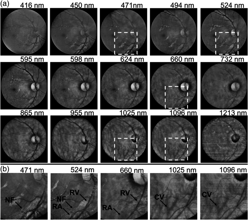
As a preliminary test to evaluate the potentiality of the MSI fundus camera, a preclinical study was conducted on healthy and diseased retinas of a small group of volunteers at the Instituto de Microcirugía Ocular (Barcelona, Spain) (Fig. 3). All patients provided written informed consent before any examination and ethical committee approval was obtained. The study complied with the tenets of the 1975 Declaration of Helsinki (Tokyo revision, 2004).
Fig. 3.
(a) Complete sequence of spectral images of a healthy eye acquired with the MSI fundus camera. (b) Zoomed images of the areas framed by a black box in (a) reveal NF, retinal arteries (RA), and veins (RV) that appear bright and dark at 660 nm due to the different absorptions of oxygenated and deoxygenated blood at this wavelength; the CV can be observed at 1025 and 1096 nm. Normalized image intensity and enhanced contrast for visualization purposes.
As anticipated, short wavelengths are reflected and scattered back more superficially, thus facilitating the observation of structures such as the optic disk and nerve fibers. In images from 500 to 700 nm, the different spectral absorptions of oxygenated and deoxygenated hemoglobin result in contrast changes between retinal veins and arteries and the surrounding fundus. For wavelengths in the NIR range, particularly those longer than 950 nm, information from layers beyond the retina such as the choroid and its vasculature is available without the use of invasive dyes due to the reduced absorption of tissue chromophores and the subsequent deeper penetration of light. Specifically, a large amount of backscattered light coming from the sclera forms the image at 1213 nm. Image acquisition beyond 1300 nm was not possible due to the high absorption of preceding ocular media and low quantum efficiency of the InGaAs camera. Notably, the image at 416 nm is of poorer quality, mainly due to the higher absorption of the lens.
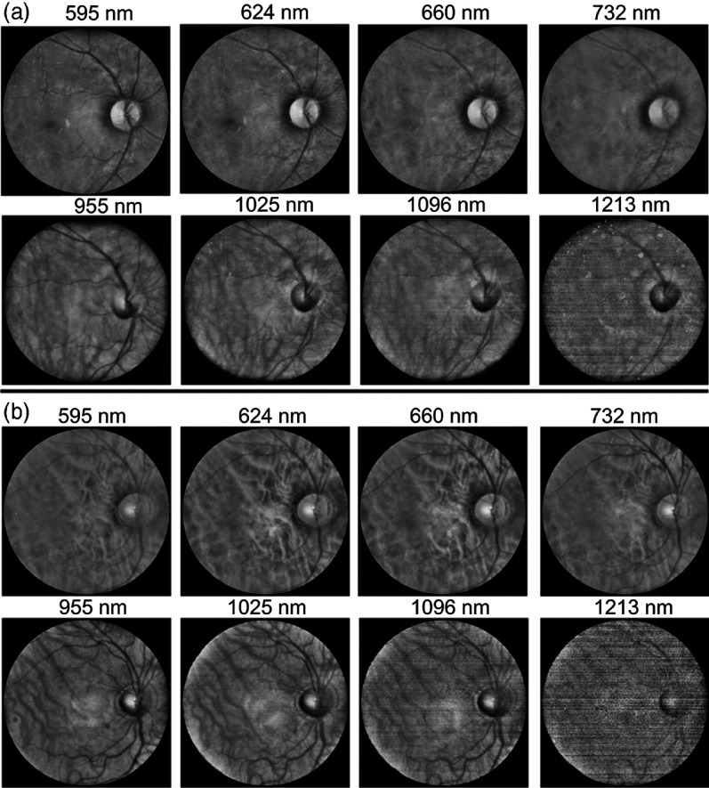
Figure 4 shows the spectral images from two healthy individuals with high and low melanin concentration. Differences between the sequences are evident: for shorter wavelengths, a high concentration of melanin hinders the visualization of deeper structures such as the CV; these structures appear only evident in the eye with less melanin. In contrast, at longer wavelengths, where melanin absorption is strongly reduced, the choroid can be seen in both cases.
Fig. 4.
Spectral images of two individuals with (a) high and (b) low melanin concentration. Normalized image intensity and enhanced contrast for visualization purposes.
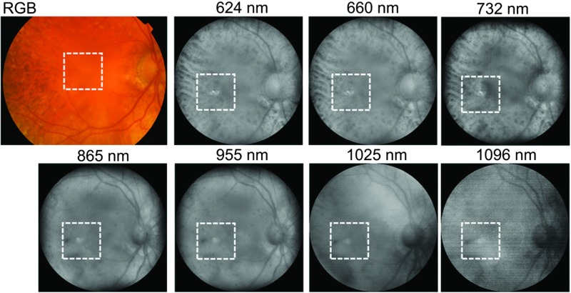
In addition, Fig. 5 shows a conventional color fundus image taken with a mydriatic retinal camera (TRC-50DX, Topcon Medical Systems, Inc., Japan) as well as spectral images of an eye of a patient aged 78 years old with an alteration of the RPE. It can be seen that while drusen-induced RPE degeneration is hardly visible in the color image, it is clearly noticeable in images corresponding to mid and long wavelengths in which light penetrates deeper into the tissue.
Fig. 5.
Color (RGB) image acquired with a mydriatic retinal camera (TRC-50DX, Topcon Medical Systems, Inc., Japan) and spectral images taken with the multispectral fundus camera of an eye with drusen-induced RPE degeneration. Normalized image intensity and enhanced contrast for visualization purposes.
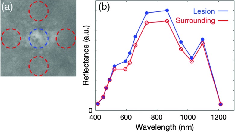
The reflectance of the RPE lesion and that of the surrounding healthy fundus is shown in Fig. 6. The reflectance of the lesion was computed as the average of the reflectance image values within a circle of 0.5-deg radius from the center of the drusen [blue circle in Fig. 6(a)]. For the estimation of the mean reflectance of the surrounding healthy tissue, four circular areas around the drusen were used [red circles in Fig. 6(a)] to minimize any local effect caused by other retinal structures. We should note that the reflectance curves are in accordance with the combined effect of the spectral fundus reflectance and ocular media transmittance:27 the values increase from blue to red, due to an increase in the retinal reflectance, and then decrease at the longest infrared wavelengths, due to the stronger absorption of the water. Nevertheless, there were relevant differences between the lesion and the surrounding tissue in terms of spectral reflectance, in particular in the red and the first NIR wavelengths. On the contrary, an analog analysis in terms of the digital levels of the three color channels of the image acquired with the conventional fundus camera provided very similar values (R, G, and B) for the degenerated RPE region (236, 106, and 27) and the surrounding tissue (231, 101, and 27), as expected.
Fig. 6.
(a) Zoom of the spectral image acquired at 732 nm with the drusen in the center. In blue and red circles, the 0.5-deg radius areas used for the estimation of the reflectance of the lesion and healthy fundus, respectively. (b) Spectral reflectance values (in a.u.) of the lesion and of the surrounding healthy areas labeled in (a).
4. Conclusions
This MSI fundus camera, which achieves fast imaging of the posterior pole at wavelengths from 400 to 1300 nm, will allow visualizing retinal and choroidal structures from an unprecedented perspective that can facilitate the early diagnosis of retinal diseases such as AMD, diabetic retinopathy, and melanomas. Currently, color retinography is the standard method to detect retinal lesions, such as drusen, exudates, neovascularization, and hemorrhages. However, they might exclude long red and NIR wavelengths, which provide additional diagnostic information, particularly from deeper layers. In contrast, MSI technology with extended sensitivity toward the NIR improves the contrast of specific retinal and choroidal structures through a spectral analysis as shown with the developed system. Moreover, it can obtain useful information on metabolic processes such as oxygenation of retinal tissues without the use of ocular angiography.
Further studies to test this prototype for clinical diagnosis are currently ongoing in the clinical setting with healthy and diseased eyes. The aim of these studies is to correlate retinal and choroidal spectroscopic observations with color and morphological findings as measured with the multispectral camera, with conventional color retinography, and with optical coherence tomography.
Acknowledgments
This work was supported by the European Commission through the MSCA project BE-OPTICAL: Advanced Biomedical Optical Imaging and Data Analysis (No. 675512) and the Spanish Ministry of Economy and Competitiveness (No. DPI2017-89414-R).
Biographies
Tommaso Alterini received his BSc degree in physics and astrophysics in 2012 and his MSc degree in physics and astrophysics in 2015 from the University of Florence. He is currently a predoctoral researcher in optical engineering at the Centre for Sensors, Instruments and Systems Development (CD6), the Universitat Politècnica de Catalunya (UPC), within the framework of the Marie Sklodowska-Curie ITN BE-OPTICAL (advanced biomedical optical imaging and data analysis). His research focuses on hyperspectral imaging for biomedical applications.
Fernando Díaz-Doutón received his PhD in optical engineering from the UPC in 2006. He is currently working as a researcher in optical engineering at the Centre for Sensors, Instruments and Systems Development (CD6, UPC), in particular in projects related to the development of new photonics-based techniques and instrumentation for different applications. His research works are mainly focused on biomedical optics, vision and instrumental optics.
Francisco J. Burgos-Fernández received his BSc degree in optics and optometry in 2008, his MSc degree in photonics in 2011, and his PhD in optical engineering in 2016 from the UPC. He is currently working as an assistant professor and a researcher at the Centre for Sensors, Instruments and Systems Development (CD6, UPC) in projects related with the development of new photonics-based techniques and instrumentation in the fields of biomedical optics, spectral imaging, and industrial colorimetry.
Laura González is coordinator of clinical trials at the Institute of Ocular Microsurgery (IMO). She belongs to the Refractive and Optometry Department of IMO and is a lecturer for the Clinical Optometry Postgraduate Diploma.
Carlos Mateo is a founding partner and ophthalmologist specialized in the retina at the IMO. He is an associate professor for the master’s course in retina and vitreous, which is run by IMO and the Faculty of Medicine at the Autonomous University of Barcelona. His main areas of interest are the pathology of high myopia, retinal detachment, severe ocular trauma, and diabetic retinopathy. His daily practice is oriented toward AMD treatment, retinal vascular disease, and diabetic macular pathology.
Meritxell Vilaseca is an associate professor at UPC. She received a PhD in optical engineering in 2005. She leads the Visual Optics and Spectral Imaging Group of the CD6. Her research works are focused on visual optics and biophotonics, color and hyperspectral imaging techniques. She has authored more than 50 papers, holds 4 patents, and has participated in more than 50 research projects.
Disclosures
No conflicts of interest, financial or otherwise, are declared by the authors.
References
- 1.More S. S., Vince R., “Hyperspectral imaging signatures detect amyloidopathy in Alzheimer’s mouse retina well before onset of cognitive decline,” ACS Chem. Neurosci. 6(2), 306–315 (2015). 10.1021/cn500242z [DOI] [PubMed] [Google Scholar]
- 2.Conigliaro P., et al. , “Take a look at the eyes in systemic lupus erythematosus: a novel point of view,” Autoimmun. Rev. 18(3), 247–254 (2019). 10.1016/j.autrev.2018.09.011 [DOI] [PubMed] [Google Scholar]
- 3.Zeng Y., et al. , “Early retinal neurovascular impairment in patients with diabetes without clinically detectable retinopathy,” Br. J. Ophthalmol. (2019). 10.1136/bjophthalmol-2018-313582 [DOI] [PubMed] [Google Scholar]
- 4.Poplin R., et al. , “Prediction of cardiovascular risk factors from retinal fundus photographs via deep learning,” Nat. Biomed. Eng. 2, 158–164 (2018). 10.1038/s41551-018-0195-0 [DOI] [PubMed] [Google Scholar]
- 5.Fawzi A. A., et al. , “Recovery of macular pigment spectrum in vivo using hyperspectral image analysis,” J. Biomed. Opt. 16(10), 106008 (2011). 10.1117/1.3640813 [DOI] [PMC free article] [PubMed] [Google Scholar]
- 6.Ami T. B., et al. , “Spatial and spectral characterization of human retinal pigment epithelium fluorophore families by ex vivo hyperspectral autofluorescence imaging,” Transl. Vision Sci. Technol. 5(3), 5 (2016). 10.1167/tvst.5.3.5 [DOI] [PMC free article] [PubMed] [Google Scholar]
- 7.Lu G., Fei B., “Medical hyperspectral imaging: a review,” J. Biomed. Opt. 19(1), 010901 (2014). 10.1117/1.JBO.19.1.010901 [DOI] [PMC free article] [PubMed] [Google Scholar]
- 8.Kim S., et al. , “Smartphone-based multispectral imaging: system development and potential for mobile skin diagnosis,” Biomed. Opt. Express 7(12), 5294–5307 (2016). 10.1364/BOE.7.005294 [DOI] [PMC free article] [PubMed] [Google Scholar]
- 9.Delpueyo X., et al. , “Multispectral imaging system based on light-emitting diodes for the detection of melanomas and basal cell carcinomas: a pilot study,” J. Biomed. Opt. 22(6), 065006 (2017). 10.1117/1.JBO.22.6.065006 [DOI] [PubMed] [Google Scholar]
- 10.Rey-Barroso L., et al. , “Visible and extended near-infrared multispectral imaging for skin cancer diagnosis,” Sensors 18(5), 1441 (2018). 10.3390/s18051441 [DOI] [PMC free article] [PubMed] [Google Scholar]
- 11.Mordant D. J., et al. , “Spectral imaging of the retina,” Eye 25(3), 309–320 (2011). 10.1038/eye.2010.222 [DOI] [PMC free article] [PubMed] [Google Scholar]
- 12.Li S., et al. , “In vivo study of retinal transmission function in different sections of the choroidal structure using multispectral imaging,” Invest. Ophthalmol. Visual Sci. 56(6), 3731–3742 (2015). 10.1167/iovs.14-15783 [DOI] [PubMed] [Google Scholar]
- 13.Johnson W. R., et al. , “Spatial–spectral modulating snapshot hyperspectral imager,” Appl. Opt. 45(9), 1898–1908 (2006). 10.1364/AO.45.001898 [DOI] [PubMed] [Google Scholar]
- 14.Gao L., et al. , “Snapshot hyperspectral retinal camera with the image mapping spectrometer (IMS),” Biomed. Opt. Express 3(1), 48–54 (2012). 10.1364/BOE.3.000048 [DOI] [PMC free article] [PubMed] [Google Scholar]
- 15.Firn K. A., et al. , “Novel, noninvasive multispectral snapshot imaging system to measure and map the distribution of human retinal vessel and tissue hemoglobin oxygen saturation,” Int. J. Ophthalmic Res. 1(2), 48–58 (2015). 10.17554/j.issn.2409-5680.2015.01.17 [DOI] [Google Scholar]
- 16.Hitchmoth D. L., “Multispectral imaging: a revolution in retinal diagnosis and health assessment,” Advanced Ocular Care 4(4), 76–79 (2013). [Google Scholar]
- 17.Nourrit V., et al. , “High-resolution hyperspectral imaging of the retina with a modified fundus camera,” J. Fr. Ophtalmol. 33(10), 686–692 (2010). 10.1016/j.jfo.2010.10.010 [DOI] [PubMed] [Google Scholar]
- 18.Everdell N. L., et al. , “Multispectral imaging of the ocular fundus using light emitting diode illumination,” Rev. Sci. Instrum. 81(9), 093706 (2010). 10.1063/1.3478001 [DOI] [PubMed] [Google Scholar]
- 19.Falt P., et al. , “Spectral imaging of the human retina and computationally determined optimal illuminants for diabetic retinopathy lesion detection,” J. Imaging Sci. Technol. 55(3), 030509 (2011). 10.2352/J.ImagingSci.Technol.2011.55.3.030509 [DOI] [Google Scholar]
- 20.Hagen N., Dereniak E. L., “Analysis of computed tomographic imaging spectrometers. I. Spatial and spectral resolution,” Appl. Opt. 47(28), F85–F95 (2008). 10.1364/AO.47.000F85 [DOI] [PubMed] [Google Scholar]
- 21.Salo D., et al. , “Multispectral imaging/deep tissue imaging: extended near-infrared: a new window on in vivo bioimaging,” BioOpt. World 7, 22–25 (2014). [Google Scholar]
- 22.ISO, “Ophthalmic instruments—fundamental requirements and test methods—part 2: light hazard protection,” ISO 15004-2:2007, International Organization for Standardization; (2007). [Google Scholar]
- 23.ISO, “Ophthalmic instruments—fundus cameras,” ISO 10940:2009, International Organization for Standardization; (2009). [Google Scholar]
- 24.Berendschot T. T., et al. , “Fundus reflectance-historical and present ideas,” Prog. Retinal Eye Res. 22(2), 171–200 (2003). 10.1016/S1350-9462(02)00060-5 [DOI] [PubMed] [Google Scholar]
- 25.Ly A., et al. , “Infrared reflectance imaging in age related macular degeneration,” Ophthalmic Physiol. Opt. 36(3), 303–316 (2016). 10.1111/opo.12283 [DOI] [PMC free article] [PubMed] [Google Scholar]
- 26.Aikens R. S., Agard D. A., Sedat J. W., “Solid-state imagers for microscopy,” Methods Cell Biol. 29, 291–313 (1989). 10.1016/S0091-679X(08)60199-5 [DOI] [PubMed] [Google Scholar]
- 27.Elsner A. E., et al. , “Infrared imaging of sub-retinal structures in the human ocular fundus,” Vision Res. 36(1), 191–205 (1996). 10.1016/0042-6989(95)00100-E [DOI] [PubMed] [Google Scholar]


