

Abstract

Owing to the properties of low density, large surface areas, excellent loading capacity, high permeability, and interstitial hollow spaces, hollow nanostructures have been widely applied in many important research fields, such as catalysis, drug-controlled release, confined synthesis, optics and electronics, and energy storage. This work provided a simple platform for hollow Cu2O nanostructure synthesis based on the surfactant controlling methodology, which is under the supposed mechanism of ion-pairing behavior at the initial nucleation stage. Thus here, we explore our system in two different directions: (1) we get different types of hollow Cu2O nanoparticles by controlling the surfactant concentration during the synthesis step in colloids, which is critical to the novel structure design and potential application in many different areas and (2) we explore the method to Cu2O hollow particle synthesis to test the hypothesis of the ion-pairing behavior during the initial nucleation by tuning the solvent ratio, cation concentration (such as NH4NO3 addition amount difference in the synthetic step), and selective etching. By tuning the synthetic conditions as well as designing control experiments, we hope to provide a solid understanding of the crystal growth mechanism. Our improved understanding in similar systems (both Cu2O and ZnO systems) will make it easier for interpreting nanostructure formation in new discoveries and, more importantly, in rationally designing various complex nanostructures based on a bottom-up strategy.
Introduction
Hollowing behavior is important to nanomaterial application because it could improve the surface area, porosity, and volume of nanomaterials.1 People studied the hollowing behavior of nanomaterials for decades to control it better. Hollow nanostructures show great potential advantages in applications, such as catalysts, batteries, and solar cells, because of their large surface area and large volume.2 Especially, the hollow oxide nanomaterials, such as silica, Ti2O, Cu2O, and ZnO, have been used in many different areas because of their unique physical and chemical properties.3 More and more studies are focused on the hollowing behavior of oxide nanostructures in order to synthesize efficient materials for applications. For example, the electrode materials, depending on their structure, morphology, particle size, and guest ions, may display pseudocapacitive or battery-like behavior whose porosity and diffusion-controlled processes are critically important to the real application.4
There are normally three main mechanisms for the oxide hollowing behavior: surface-selective etching under protection,5 Ostwald ripening,5 and surface redeposition.6,7 For example, Yin’s group has reported that poly(vinylpyrrolidone) (PVP) can protect the outmost silica layer from etching while PVP is absorbed on the silica nanoparticle surface.5 It cannot protect the inner layer because the PVP molecule size is larger than the silica pore size to diffuse inside.8,9
In our previous work, we synthesized the sol–gel silica nanoparticles and analyzed the silica composition via elemental analysis and inductively coupled plasma mass spectroscopy, and we found that certain amounts of N and C are trapped within the silica nanoparticles, which shall be from the incorporation of ammonia cations and unhydrolyzed tetraethyl orthosilicate (TEOS) and solvent isopropanol. The ion-pairing mechanism was introduced to explain the phenomenon. NH3 not only catalyzed the hydrolysis of TEOS but also functionalized as a deprotonating agent to facilitate the formation of ion pairs with silicate species, which has a great influence on the formation and dissolution of silica nanoparticles. The ion-paired silica species with a longer chain length will preferentially precipitate out in nonpolar solution (alcohol) and form aggregates. These silica aggregates can function as the seeds for further growth of silica species with a short chain length in the monomer addition mode. When they are transferred to an aqueous solution for etching, the inner part of silica can dissociate into soluble species, while the outer layer is cross-linked and not etchable, which eventually leads to the formation of hollow silica nanoparticles.10
Here, we report a method to synthesize hollow oxide nanostructures by using PVP as a surfactant/ligand. The porosity as well as the morphology of the nanostructures could be controlled by tuning the PVP concentration, solvent ratio, and growth solution environment. These parameters are critical to the synthetic control, which could give novel nanostructures showing unique physical properties, such as high porosity, large surface area, various morphologies, and so on.
Results and Discussion
First, Cu2O nanoparticles were synthesized in colloids. Typically, DI water containing PVP (different concentrations of 0–12 mg/mL) aqueous solution was added to a 20 mL glass vial heated at 60 °C by using an oil bath to dissolve PVP to give a homogeneous clear solution. Then, CuCl2 aqueous solution and NaOH aqueous solution were added in sequence under vigorous stirring to mix the solutions quickly. The NaOH solution was added to tune the pH of the solution. Finally, a hydrazine hydrate solution (reducing agent) was added by dropping (droplet addition) with vigorous stirring. To study the hollowing mechanism in the ion-pairing hypothesis, different parameters were changed in the synthesis step, such as the ligand/surfactant concentration, salt concentration, and solvent ratio.10−12 All the nanocrystals have been characterized by transmission electron microscopy (TEM), scanning electron microscopy (SEM), and XRD to confirm the structure here.
For the Cu2O nanocube synthesis, we find that the surfactant poly(vinylpyrrolidone) (PVP) concentration is critical to the final morphologies. A PVP concentration increase from 0 to 12 mg/mL could lead to surfactant micelles and different adsorption on the primary nucleation seed surface, which might be embedded inside the crystal.13,14 As shown in Figure 1, hollow Cu2O nanocubes were collected at a high concentration of PVP solution during the synthesis. The Cu2O nanocubes synthesized at a lower PVP concentration or without any PVP addition show a high density with a regular cubic shape. However, the nanoparticle morphology changed with PVP addition, especially the void that appeared in the center of the nanoparticles (Figure 1a–f). Also, the cubic shape changed from a cubic morphology to a not regular cubic one. Here, it is clear that the PVP and copper ions form a kind of cluster/template at the initial stage of the crystal nucleation, which is similar to the ionic polymer (polyelectrolyte) behavior.14 With knowledge of ionic polymers, the stability of the polymers in a solution is highly related with the concentration of counterions and solvent polarity in the growth solution. The counterionized polymers could be precipitated out under a nonpolar or lower polar environment and trap more organic molecules (or oligomers) to give hollow/porous nanostructures. Especially, when the surfactant concentration is very high (higher than 8 mg/mL), the nanocube would be heavily hollowed. The HRTEM data in Figure 2 show that it is a mesocrystal-like crystal. Here, this kind of control has never been reported for the Cu2O nanocube synthesis. As it has been reported that PVP could be used as a template to synthesize some porous/hollow nanoparticles,15 systematically studying the PVP concentration effects on porous morphology has never been done (PVP–copper clusters showing polyelectrolyte-like properties). Also, this unique understanding demonstrates a series of control experiments to test the ion-pairing hypothesis, such as the addition of counterions in the synthesis, change of the solvent polarity, and using different types of surfactants in the synthesis.
Figure 1.

TEM images showing the purified products of Cu2O nanocubes synthesized at different surfactant PVP concentrations of (a) 2, (b) 4, (c) 6, (d) 8, (e) 10, and (f) 12 mg/mL. Heavier hollowing at higher PVP concentration is clear.
Figure 2.

HRTEM images showing the purified products of Cu2O nanocubes synthesized at a surfactant PVP concentration of 6 mg/mL. (a) TEM image of the nanocube. (b) HRTEM image showing the edge of the sample in panel a. (c) SAED image of the sample in panel a. (d) STEM image of the sample in panel a showing the porous property of the nanoparticle synthesized with PVP solution. (e) XRD spectrum of the sample in panel a. (f) EDX color maps of the Cu2O hollow crystal shown in Figure 1f.
As shown in Figure 2a,b, the clear (111) and (110) lattice fringes of Cu2O nanocrystals can be observed, and the XRD spectrum in Figure 2e also confirms the presentation of the nanocrystal phase. Interestingly, the EDX maps shown in Figure 2f (also, see the Supporting Information) clearly present the hollow morphology of the cube synthesized in the presence of PVP aqueous solution, identifying the successful synthetic control of hollow/porous metal nanocrystals in colloids. In order to clarify the porous nanoparticle formation, we conducted a EDX line scan to the final hollow nanoparticles, as shown in Figure S5 where Cu distribution shows the trajectory of the porous morphology, while carbon distribution is homogeneous in the whole area, which may be contributed by the carbon contamination as well as the TEM grid (carbon layer on the grid).
For the Cu2O nanocube coating another spherical layer of Cu2O, we have tried to introduce the salt (NH4NO3) into the synthesis, which will help us to know whether the counterions can affect the oxide formation and hollowing, just like how it happens in the silica nanoparticle formation process. As the hypothesis shows above, the presence of ion pairs plays a very important role in pore formation and cube morphology, which is attributed to surface crystallization dynamic difference caused by polyelectrolyte-like cluster formation. Therefore, by changing the nature of ion pairs, we may further tune the solubility of cluster-like species in the primary nucleation stage. Intentionally, we added certain amounts of salts like NH4NO3 under the synthetic condition. Because the NH4+ ions can be counterionized with negatively charged PVP–copper polyelectrolyte-like clusters, they immediately aggregated to form oligomers. These are more likely to aggregate due to a lower solubility and fast deposition kinetics in different polar solvents, as shown in Figures 3 and 6a.
Figure 3.

TEM images showing the purified products of Cu2O nanocubes@Cu2O spherical shell at different salt (NH4NO3) concentrations of (a) 0, (b) 2, (c) 4, and (d) 8 mM. It is clear that a higher salt concentration gives a heavier hollowing of core–shell nanoparticles.
Figure 6.

(a) Schematics illustrating the significant role of ion pairing in the formation of hollow Cu2O nanoparticles. (b) TEM images showing the primary nucleation–crystallization-selective etching steps of the Cu2O crystal.
According to Figure 3, it is clear to see that the spherical Cu2O shell morphologies are different at different salt (NH4NO3) concentrations. Typically, the core–shell nanoparticle was the final product without any NH4NO3 addition; it will be lightly hollowed at the interface of the nanocube core and the spherical shell when the salt (NH4NO3) concentration is 2 mM; the heavily hollowed shell would be observed when the salt (NH4NO3) concentration is increased to 8 mM or higher. The trend between the salt (NH4NO3) concentration and the spherical shell morphology is clearly seen there.15,16 We think it is possible that ion doping caused by the ion concentration difference might affect the shell morphology.17−19 Previously, van Blaaderen and Kentgens investigated the structure of the siloxane network in silica particles by nuclear magnetic resonance spectroscopy, which revealed the existence of a small amount of clusters (oligomers) due to incomplete hydrolysis and condensation of TEOS. Similarly, PVP–Cu ion groups not only change the homogeneity in the internal structure of oxide particles but also affect the external morphology, as shown in this work.20,21
From a polyelectrolyte (or ionic polymer) point of view, the stability of the polymers/clusters in solution is highly related to the counterion concentration and solvent polarity. Based on its physical property, the solvent polarity can also have a great influence on the ion-pairing kinetics and also the surface nucleation. Since the solvent is a mixture of water and ethanol, different ratios between the two can give a different polarity, which shall lead to different deposition kinetics of Cu2O nanoparticles.
The solvent ratio control experiments (Figure 4) of the nanostructure formation during the synthetic step show the trend clearly: at higher water content (EtOH/water = 1:4), the main product is the dense nanoparticles, as shown in Figure 4a. However, with an ethanol concentration increase in the solvent mixture, there would be heavier porous nanoparticle formation, as shown in Figure 4b,c. The trend of nanoparticle shell thickness (as well as size) change with the solvent ratio (ethanol/water volume ratio) change is shown in Figure 4d, which could tell the solvent polarity effect clearly. Theoretically, the higher the solvent polarity is, the easier the PVP–Cu ionic polymer to precipitate out. As for cluster species like monomers, dimers, or trimers, they will deposit on the precipitates in a manner that is quite different from the traditional crystallization (also called the polymer-trapped process, as shown in Figure 6a). This explains both the void/pore formation in the center of the nanoparticle and the cube-to-sphere overall nanoparticle morphology change.
Figure 4.

TEM images showing the purified products of Cu2O nanocubes@Cu2O spherical shell at different solvent volume ratios of EtOH/water: (a) 1:4, (b) 1:1, and (c) 4:1. (d) Shell thickness of Cu2O nanoparticles at different solvent ratios. It is clear that lower polarity of the mixing solvent leads to heavier hollowing while giving a thinner shell for the Cu2O nanocubes@Cu2O spherical nanoparticle.
Brunauer–Emmett–Teller (BET) data shown in Figure 5 also support our hypothesis. For the Cu2O nanoparticles synthesized at a lower salt (NH4NO3) concentration, the BET data show that it has a smaller surface area (68.74 cc/g); for the Cu2O nanoparticles synthesized at a higher salt (NH4NO3) concentration, the BET data show that it has a large surface area (83.15 cc/g). The result means that at a higher salt concentration, the Cu2O nanoparticle porosity would be higher compared to that at the lower salt concentration. It can be explained under the ion doping mechanism, which means that a higher salt concentration might lead to a heavier ion doping inside the Cu2O nanoparticles by quick precipitation, which would trap more counterions inside. Then, there would be more defects inside the Cu2O nanoparticles leading to high porosity. However, the PVP–Cu clusters have more condensation time to grow into higher cross-linking clusters with higher crystallization, which in turn gives crystals with lower or no defect, showing a perfect cubic morphology and a dense solid domain without visible voids inside.
Figure 5.

TEM images showing the purified products of Cu2O nanocubes@Cu2O spherical nanoparticle at different salt (NH4NO3) concentrations of (a) 0 and (b) 4 mM. Corresponding nitrogen adsorption/desorption isotherm curve (BET data) to show the surface areas of the two samples: (c) 0 and (d) 4 mM.
To understand the scenario of copper oxide morphology evolution at different stages, a key observable trend should be the shape transformation gallery, as shown in Figure 6a,b. As a common sense for polyelectrolytes, the solubility of the ion-paired polymer-like species should depend on the solvent polarity, positively charged ion concentration, and the primary cluster chain length, which are also variable at the different stages of Cu2O nanocrystal formation. Considering the higher concentration of precursor at the initial stage, it is expected that a large size polymer chain would form. They would preferentially nucleate due to their low solubility, wrapping in with them a large number of counterions as well as PVP molecules. In contrast, the outer layer was built up from the subsequent addition of the leftover monomers and short-length polymers. These shorter polyelectrolytes retain less counterions and eventually give more cross-linked shells by crystallization. Hence, the dramatic difference between the two stages leads to an abrupt boundary of different deposition dynamics, which could give a hollow/porous structure after the addition of a high concentration PVP (cluster size is larger), higher positively charged ion concentration (concentrated ion-pairing formation), or higher ethanol/water ratio (lower polarity solvent leads to fast cluster precipitation with rich defects). We also characterize the intermediates of the crystal formation process, as shown in Figure 6b, by trapping the intermediates. It is clear to see that there are polymer-like species at the initial stage of nucleation (5 min after the reducing agent addition), which is an amorphous-like material (with the presence of the PVP). This trend supports our hypothesis of ion-paired polymer-like formation.
With the above knowledge, we could enrich the structure map of Cu2O by adjusting the critical parameters, which could affect the ion-pairing behavior. Hence, in Figure 7, we summarized the hollow and porous nanoparticle formation, which is dependent on the experimental environments. With a higher PVP concentration, as shown in Figure 7a, more polymer-like amorphous material formation gives hollow-like particles. Similarly, a highly porous particle was the main product when a high cation concentration is present in the synthesis solution, as shown in Figure 7b, which could lead to more ion-pairing behavior at the initial stage of nucleation to trap more noncrystals within the nanoparticle domain. Finally, the water content (solvent volume ratio of ethanol/water) also plays an important role in the ion-pairing process, as shown in Figure 7c; a lower water concentration will lead to more amorphous polymer-like species formation at the initial stage of nucleation, which gives a porous-like nanoparticle rather than dense single- or polycrystalline nanoparticles. All these control experiments support our hypothesis of ion-pairing behavior during the Cu2O formation in different solutions. Here, to explore this mechanism with other metal oxide synthesis, ZnO nanoparticle synthesis was chosen as another model study. As shown in Figure S6, ZnO hollow nanoparticles were observed when PVP was introduced in the synthetic step under different concentrations or under different solvent ratios (Figure S7), which shows a similar trend with Cu2O synthesis. As a comparison, we found that the ZnO nanoparticle hollowing behavior also depends on its ion-pairing behavior. We believe that it is helpful to the hollow mechanism study although it might be at a different level for different systems.
Figure 7.
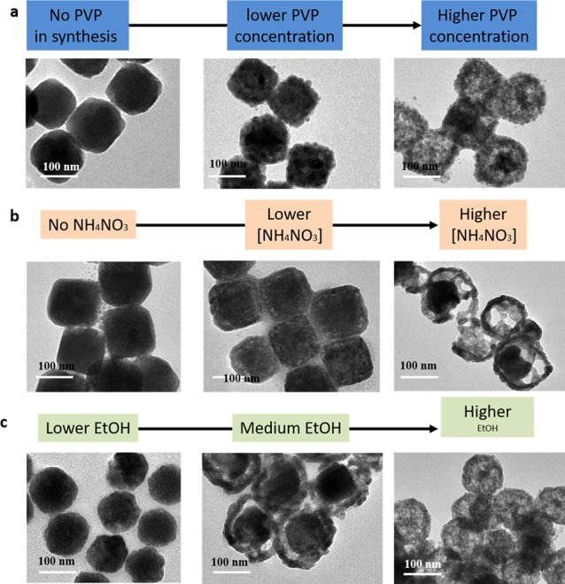
Cu2O nanoparticle morphology changes when these nanoparticles were synthesized under different conditions. TEM images of the Cu2O nanoparticles synthesized under (a) different PVP concentrations as shown in the chart flow ([PVP] = 2, 6, and 16 mg/mL, respectively), (b) different NH4NO3 concentrations as shown in the chart flow ([NH4NO3] = 0, 4, and 8 mM, respectively), and (c) different water concentrations as shown in the chart flow (ethanol/water volume ratio = 1/8, 1/1, 8/1, respectively).
Conclusions
In summary, we report a facile method to prepare hollow/porous copper oxide nanoparticles by controlling the ion-pairing behavior. By playing with the surfactant concentration, solvent ratio, and cation concentration, we achieved different types of hollow/porous nanoparticles, suggesting a new pathway in nanomaterial design. Our proof of concept is that the ion-pairing polymer-like behavior in the synthetic approach can create new morphologies of copper oxides (as well as ZnO), which is a clear demonstration for the porous/hollow nanoparticle design as well as its potential applications in catalysts, batteries, sensors, and so on.22−27
Experimental Section
Materials
Copper chloride (CuCl2, 98%, Aldrich), hydrazine hydrate (N2H4·H2O, 99.8%, Alfa Aesar), ammonium nitrate (NH4NO3, Aldrich), poly(vinylpyrrolidone) (PVP, Mw of 40,000, Aldrich), and sodium hydroxide (NaOH, 98%, Aldrich) were used as received without any further purification. All glassware for nanoparticle syntheses was treated with aqua regia (a mixture of HCl and HNO3 with a volume ratio of 3:1), thoroughly rinsed with water, and dried under N2 gas immediately before use. Nanopure water (18.2 MΩ·cm at 25 °C) purified using a Milli-Q Advantage A10 system was used for all washing and solution preparation.
Synthesis of Cu2O Nanoparticles (Different PVP Concentrations)
In order to test PVP concentration effects, the typical synthesis procedure was as the following that 9.0 mL of pure DI water and 7.7 mL of DI water containing PVP (with different concentration from 0 to 12 mg/mL) were sequentially added into a 20 mL glass vial. The mixture was heated at 60 °C by using an oil bath. Then, 0.1 mL of 0.15 M CuCl2 aqueous solution and 0.1 mL of 0.1 M NaOH aqueous solution were added under vigorous stirring (600 rpm) in that order. The NaOH solution was added drop by drop under stirring. Finally, 0.15 mL of 0.25 M N2H4 solution (reducing agent) was added by dropping (droplet addition) with vigorous stirring. The final mixed solution was aged in an oil bath for another 1 h. The as-synthesized nanoparticles were purified by centrifugation at 8000 rpm for 8 min three times to remove the impurities.
Synthesis of Cu2O Nanoparticles (Different Solvent Ratios)
To the solvent ratio control experiments, 9.0 mL of ethanol/water mixed solvent (at different volume ratios) was added at the beginning, instead of using pure water. For the synthesis experiments under different solvent ratios, every step is the same as above except the usage of 9 mL of pure water, which was replaced by the mixture of water and ethanol.
Synthesis of Cu2O Nanoparticles (Different Ion Concentrations)
To test the positively charged ion effect on ion-pairing behavior, ammonium nitrate (NH4NO3) was added into the solution to give a solution with different cation molar concentrations (0, 2, 4, and 6 mM) at the beginning of the synthesis. Then, 0.1 mL of 0.10 M CuCl2 aqueous solution and 0.1 mL of 0.1 M NaOH aqueous solution were added under vigorous stirring (600 rpm), whose following procedure is the same as above sections.
Characterization
TEM images were collected from a JEM-1400 (JEOL) transmission electron microscopy operated at 100 kV. High-resolution TEM (HRTEM) and energy-dispersive X-ray (EDX) images were taken from a JEOL 2100F field emission transmission electron microscope at 200 kV. X-ray diffraction (XRD) data were collected using a Bruker D8-Advance θ–2θ diffractometer in reflectance Bragg–Brentano geometry employing Ni-filtered Cu Kα line focused radiation at 1600 W (40 kV, 40 mA) power and equipped with a Na(Tl) scintillation detector fitted with a 0.2 mm radiation entrance slit. All samples were ground to ensure monodispersity in the bulk and then mounted onto a zero-background sample holder by dropping powders from a wide-blade spatula, and the sample surface was then leveled with a razor blade. BET surface area and pore size measurements were conducted with N2 adsorption/desorption isotherms at 77 K on a Micromeritics ASAP 2020 v3.04 H instrument.
Acknowledgments
The authors thank the Molecular Foundry of Lawrence Berkeley National Lab and the Department of Materials Science and Engineering at UC Berkeley for discussion and technique support in sample characterization.
Supporting Information Available
The Supporting Information is available free of charge at https://pubs.acs.org/doi/10.1021/acsomega.9b03380.
-
The Supporting Information is available free of charge on the ACS Publications website.
Experimental procedures, figures of the control experiments, and photo of the reaction color change (PDF)
Author Contributions
All authors contributed to the manuscript preparation and experimental design and discussion. The sample preparation was done by X.S., X.L., and W.X. TEM images were collected by X.S. and D.S. EDX line scan was collected by X.S., X.L., and J.T.
The research was supported by A*STAR (SERC 112–120-2011) and MOE (RG14/13) of Singapore.
The authors declare no competing financial interest.
Supplementary Material
References
- Lou X. W. D.; Archer L. A.; Yang Z. Hollow micro–/nanostructures: Synthesis and applications. Adv. Mater. 2008, 20, 3987–4019. 10.1002/adma.200800854. [DOI] [Google Scholar]
- Zhang Q.; Wang W.; Goebl J.; Yin Y. Self-templated synthesis of hollow nanostructures. Nano Today 2009, 4, 494–507. 10.1016/j.nantod.2009.10.008. [DOI] [Google Scholar]
- Yang H. G.; Zeng H. C. Preparation of Hollow Anatase TiO2 Nanospheres via Ostwald Ripening. J. Phys. Chem. B 2004, 108, 3492–3495. 10.1021/jp0377782. [DOI] [PubMed] [Google Scholar]
- Liu J.; Wang J.; Xu C.; Jiang H.; Li C.; Zhang L.; Lin J.; Shen Z. X. Advanced Energy Storage Devices: Basic Principles, Analytical Methods, and Rational Materials Design. Adv. Sci. 2018, 5, 1700322–1700340. 10.1002/advs.201700322. [DOI] [PMC free article] [PubMed] [Google Scholar]
- Zhang T.; Ge J.; Hu Y.; Zhang Q.; Aloni S.; Yin Y. Formation of hollow silica colloids through a spontaneous dissolution–regrowth process. Angew. Chem., Int. Ed. 2008, 47, 5806–5811. 10.1002/anie.200800927. [DOI] [PubMed] [Google Scholar]
- Yec C. C.; Zeng H. C. Synthesis of complex nanomaterials via Ostwald ripening. J. Mater. Chem. A 2014, 2, 4843–4851. 10.1039/C3TA14203E. [DOI] [Google Scholar]
- Oh W.-K.; Kim S.; Choi M.; Kim C.; Jeong Y. S.; Cho B.-R.; Hahn J.-S.; Jang J. Cellular uptake, cytotoxicity, and innate immune response of silica– titania hollow nanoparticles based on size and surface functionality. ACS Nano 2010, 4, 5301–5313. 10.1021/nn100561e. [DOI] [PubMed] [Google Scholar]
- Lou X. W.; Wang Y.; Yuan C.; Lee J. Y.; Archer L. A. Template-Free Synthesis of SnO2 Hollow Nanostructures with High Lithium Storage Capacity. Adv. Mater. 2006, 18, 2325–2329. 10.1002/adma.200600733. [DOI] [Google Scholar]
- Ciriminna R.; Fidalgo A.; Pandarus V.; Béland F.; Ilharco L. M.; Pagliaro M. The sol-gel route to advanced silica-based materials and recent applications. Chem. Rev. 2013, 113, 6592–6620. 10.1021/cr300399c. [DOI] [PubMed] [Google Scholar]
- Song X.; Ding T.; Yao L.; Lin M.; Siew Tan R. L.; Liu C.; Sokol K.; Yu L.; Lou X. W. D.; Chen H. On the origin and underappreciated effects of ion doping in silica. Small 2015, 11, 4351–4365. 10.1002/smll.201500539. [DOI] [PubMed] [Google Scholar]
- Slowing I. I.; Vivero-Escoto J. L.; Trewyn B. G.; Lin V. S. Y. Mesoporous silica nanoparticles: structural design and applications. J. Mater. Chem. 2010, 20, 7924–7937. 10.1039/c0jm00554a. [DOI] [Google Scholar]
- Wang X.; Schröder H. C.; Wang K.; Kaandorp J. A.; Müller W. E. G. Genetic, biological and structural hierarchies during sponge spicule formation: From soft sol–gels to solid 3D silica composite structures. Soft Matter 2012, 8, 9501–9518. 10.1039/c2sm25889g. [DOI] [Google Scholar]
- Wong Y. J.; Zhu L.; Teo W. S.; Tan Y. W.; Yang Y.; Wang C.; Chen H. Revisiting the stÖber method: inhomogeneity in silica shells. J. Am. Chem. Soc. 2011, 133, 11422–11425. 10.1021/ja203316q. [DOI] [PubMed] [Google Scholar]
- Fang X.; Zhao X.; Fang W.; Chen C.; Zheng N. Self-templating synthesis of hollow mesoporous silica and their applications in catalysis and drug delivery. Nanoscale 2013, 5, 2205–2218. 10.1039/c3nr34006f. [DOI] [PubMed] [Google Scholar]
- Chen Y.; Chen H.; Guo L.; He Q.; Chen F.; Zhou J.; Feng J.; Shi J. Hollow/rattle-type mesoporous nanostructures by a structural difference-based selective etching strategy. ACS Nano 2010, 4, 529–539. 10.1021/nn901398j. [DOI] [PubMed] [Google Scholar]
- Ding T.; Yao L.; Liu C. Kinetically controlled synthesis of ultra-small silica nanoparticles and ultra-thin coatings. Nanoscale 2016, 8, 4623–4627. 10.1039/C5NR08224B. [DOI] [PubMed] [Google Scholar]
- Yu Q.; Wang P.; Hu S.; Hui J.; Zhuang J.; Wang X. Hydrothermal synthesis of hollow silica spheres under acidic conditions. Langmuir 2011, 27, 7185–7191. 10.1021/la200719g. [DOI] [PubMed] [Google Scholar]
- Park S.-J.; Kim Y.-J.; Park S.-J. Size-dependent shape evolution of silica nanoparticles into hollow structures. Langmuir 2008, 24, 12134–12137. 10.1021/la8028885. [DOI] [PubMed] [Google Scholar]
- Liu X.; Jiao Z.; Song T.; Wu M.; Zhang H. Surfactant-assisted selective etching strategy for generation of rattle-like mesoporous silica nanoparticles. J. Colloid Interface Sci. 2017, 490, 497–504. 10.1016/j.jcis.2016.11.083. [DOI] [PubMed] [Google Scholar]
- van Blaaderen A.; Kentgens A. P. M. Particle Morphology and Chemical Microstructure of Colloidal Silica Spheres Made from Alkoxysilanes. J. Non-Cryst. Solids 1992, 149, 161–178. 10.1016/0022-3093(92)90064-Q. [DOI] [Google Scholar]
- Hu Y.; Zhang Q.; Goebl J.; Zhang T.; Yin Y. Control over the Permeation of Silica Nanoshells by Surface-protected Etching with Water. Phys. Chem. Chem. Phys. 2010, 12, 11836–11842. 10.1039/c0cp00031k. [DOI] [PubMed] [Google Scholar]
- Chen S. L.; Dong P.; Yang G. H.; Yang J. J. Kinetics of formation of monodisperse colloidal silica particles through the hydrolysis and condensation of tetraethylorthosilicate. Ind. Eng. Chem. Res. 1996, 35, 4487–4493. 10.1021/ie9602217. [DOI] [Google Scholar]
- Li L.; Zhang L.; Xing S.; Wang T.; Luo S.; Zhang X.; Liu C.; Su Z.; Wang C. Generalized Approach to the Synthesis of Reversible Concentric and Eccentric Polymer-Coated Nanostructures. Small 2013, 9, 825–830. 10.1002/smll.201201735. [DOI] [PubMed] [Google Scholar]
- Liu J.; Qiao S. Z.; Liu H.; Chen J.; Orpe A.; Zhao D.; Lu G. Q. M. Extension of the Stöber method to the preparation of monodisperse resorcinol–formaldehyde resin polymer and carbon spheres. Angew. Chem., Int. Ed. 2011, 50, 5947–5951. 10.1002/anie.201102011. [DOI] [PubMed] [Google Scholar]
- Song X.; Smith J. W.; Kim J.; Zaluzec N. J.; Chen W.; An H.; Dennison J. M.; Cahill D. G.; Kulzick M. A.; Chen Q. Unraveling the Morphology–Function Relationships of Polyamide Membranes Using Quantitative Electron Tomography. ACS Appl. Mater. Interfaces 2019, 11, 8517–8526. 10.1021/acsami.8b20826. [DOI] [PubMed] [Google Scholar]
- Ma Y.; Zhu X.; Xu S.; He G.; Yao L.; Hu N.; Su Y.; Feng J.; Zhang Y.; Yang Z. Gold Nanobipyramid@Cuprous Oxide Jujube-Like Nanostructures for Plasmon-Enhanced Photocatalytic Performance. Appl. Catal., B 2018, 234, 26–36. 10.1016/j.apcatb.2018.04.014. [DOI] [Google Scholar]
- Ma Y.; Li X.; Yang Z.; Xu S.; Zhang W.; Su Y.; Hu N.; Lu W.; Feng J.; Zhang Y. Morphology Control and Photocatalysis Enhancement by in-Situ Hybridization of Cu2O with Nitrogen-Doped Carbon Quantum Dots. Langmuir 2016, 32, 9418–9427. 10.1021/acs.langmuir.6b02011. [DOI] [PubMed] [Google Scholar]
Associated Data
This section collects any data citations, data availability statements, or supplementary materials included in this article.