Abstract
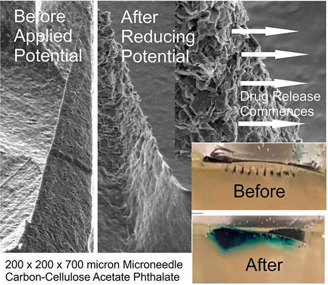
Transdermal microneedles have captured the attention of researchers in relation to a variety of applications, and silicone-based molds required to produce these systems are now widely available and can be readily manufactured on the lab bench. The production of nanocomposite microneedle arrays through micromolding techniques is described. The formulation of nanoparticulate carbon along with pH sensitive cellulose acetate phthalate as a polymeric binder is shown to produce conductive microneedles whose swelling/dissolution properties can be controlled electrochemically. Through exploiting hydrogen evolution at the microneedle array, changes in local pH can induce swelling within the needle structure and could lay the foundations for a new approach to the smart device controlled delivery of therapeutic agents. The surface modification of the carbon needles with palladium and cysteine is critically assessed from sensing and drug delivery perspectives.
Keywords: microneedle, transdermal, smart patches, palladium, HER, drug delivery
Introduction
Microneedle systems are increasingly being heralded as a technological step change in drug delivery applications and can offer a multitude of advantages over conventional syringe-based approaches.1−9 These microneedle (MN) systems typically comprise an array of sub-millimeter sized projections (50–900 μm) and, in contrast to conventional hypodermic injections, are sufficiently small that the shallow penetration depth typically fails to trigger the dermal nerve network.9−11 The near-painless puncture of the skin barrier allows the transport of a large variety of drugs and vaccines to the underlying microcirculation, and the success of the general strategy has seen a near exponential rise in publications.3 There are generally five classes of MN system: solid, coated, hollow, dissolvable, and swellable. Each has its own merits and limitations, and they have been extensively reviewed.1−9 As the development of MN patches has continued apace, there has been a trickle-down availability of the technologies required to produce them with silicone molds allowing rapid, low cost, soft lithographic production within conventional laboratory environments.1,2,12,13 The processes can be adapted for preparing all bar the hollow designs. The aim of the present communication has been to investigate the development of composite solid microneedles consisting of polymer encapsulated nanocarbon. The intention was to create electrochemically conductive MN arrays that could, in principle, offer the potential for electrochemical techniques to be applied such that the MN patches could possess sensing capabilities but, more importantly, could also be used to control drug release. The latter sits at the core of the approach, as the electronic control over the release mechanism could offer a new approach in MN design.
The rationale adopted here revolves around the use of cellulose acetate phthalate (CAP) as the binding polymer used to maintain the integrity of the needle structure. In contrast to more benign polymer systems used in MN manufacture (i.e., polycarbonate or polystyrene12,13), CAP is pH sensitive and is already used in a multitude of oral drug formulations.14−18 The CAP outer layer is stable in the acid of the stomach but dissolves upon reaching the alkaline environments of the colon.16,17 Exploitation of the pH sensitivity of the polymer for use in electrochemically controlled drug release has been described previously but in the context of its use as a film encapsulating a drug loaded reservoir.19 The intention here was to use the CAP matrix as the binding medium within which nanocarbon particles would be mixed to yield a composite microneedle but which could swell or dissolve upon changes in local pH brought about by the imposition of a suitably reducing potential. The latter relates to the hydrogen evolution reaction (HER), whereby there is an increase in local pH at the electrode as a consequence of the reduction process.19 It could be envisaged therefore that, were the HER reaction to be imposed at the MN array, the increase in local pH would lead to the swelling (and possible dissolution) of the CAP polymer that constitutes the needle structure. Thus, were drugs to be entrapped within the network at the time of formulation, then the electrochemically induced swelling could allow control over their release. The ultimate embodiment of the proposed electrochemically driven strategy is highlighted in Figure 1. There is a burgeoning interest in the use of dissolvable and swellable MN systems for drug release,1−9 and although the formulation process is similar to that proposed here, the release process for those is inherently passive. It was therefore of interest to determine whether the introduction of the nanocarbon particles could facilitate the development of a controlled release mechanism and to critically evaluate the merits and limitations that such systems would present for transdermal drug delivery.
Figure 1.
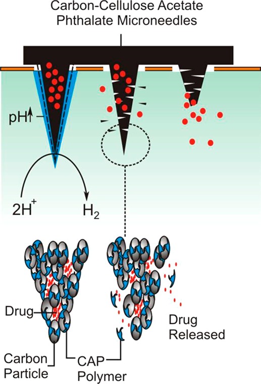
Overview of the proposed, electrochemically initiated release mechanism
Materials and Methods
Electrochemical analysis was performed utilizing a μAutolab Type III computer operated potentiostat (Eco-Chemie, Utrecht, The Netherlands). All measurements were conducted at 22 ± 2 °C. Nanocarbon powder was supplied by Sigma-Aldrich with a mean particle size of 100 nm. Silicone MPatch microneedle templates were purchased from Micropoint Technologies Pte Ltd. (CleanTech Loop, Singapore). The initial measurements involved a three-electrode configuration consisting of a carbon–polymer composite MN working electrode, a counter electrode in the form of a platinum wire, and a standard silver/silver chloride (3 M NaCl, BAS Technicol UK) reference electrode.
Microneedle Fabrication
Production of the MNs was generally achieved through the simple mixing and dispersion of the nanocarbon (Sigma-Aldrich) within the polymer (50/50 wt %) that had previously been dissolved in a suitable solvent such as cyclohexanone. The silicone molds were obtained from Micropoint Technologies and typically consisted of a 10 × 10 MN array. The needle dimensions used in the studies were either 200 × 200 × 350 μm or 200 × 200 × 700 μm. The molds were cleaned by sonication, the polymer–carbon mixture was added, and the solvent was allowed to evaporate. The use of a vacuum oven (under ambient temperature) was found to greatly improve the speed of the production process and needle quality through accelerating the removal of trapped solvent. In the case of microneedle arrays loaded with Toluidine Blue (TBO), the silicone molds were initially coated with carbon–CAP solution to yield a coherent but conductive interface. A second mixture of the carbon–CAP containing 1% TBO was then introduced, and the needles were cured as specified previously.
Microneedle Modification
The nanocarbon–CAP microneedles were sputtered with a thin layer of palladium using a 80:20 Pd/Au target at 30 mA for 3 min (Emitech K500X Sputter Coater, Quorum Technologies Ltd., England). X-ray photoelectron spectroscopy (XPS) of the palladium samples before and after modification with cysteine was performed using an Axis Ultra DLD spectrometer (Kratos Analytical, Japan) using monochromated Al Kα X-rays (15 kV and 10 mA) with an operating pressure lower than 6 × 10⁻⁸ Pa. A hybrid lens mode was used during analysis, and charge neutralization was achieved using an immersion lens with a filament current of between 1.7 and 2.1 mA at a charge balance voltage of between 3.0 and 3.6 V. Three spots were analyzed per sample with wide energy survey scans (0–1300 eV binding energy) as well as high resolution spectra for Pd 3d, C 1s, N 1s, O 1s, and S 2p. The pass energy was 160 eV for the wide energy survey scans and 20 eV for the high resolution spectra.
Biocompatibility Studies
The biocompatibility of the nanocarbon–cellulose acetate composite was assessed in relation to skin irritation (DIN EN ISO 10993-10:2014) and cytotoxicity (DIN EN ISO 10993-5:2009) and conducted by Bioserv Analytik Un Medizinprodukte GMBH (Rostock Germany) under GLP conditions.
Skin irritation assessments were conducted using healthy young female albino rabbits with a weight not less than 2 kg (as per ISO recommendations). The rabbits were kept caged for at least 5 days prior to the test to enable acclimatization and were immunized against myxomatosis and RHD. The fur on the back of the rabbits was closely clipped on both sides of the spinal column (10 × 15 cm) 4 h before the test procedure was initiated. The test material (C–CAP) was applied directly to the clipped skin along with gauze patches that served as a control (25 × 25 mm). The sites were then covered with a nonocclusive gauze patch and then wrapped with an occlusive bandage for a period of 4 h. At the end of the test, the dressings were removed, and any residual substances were washed with warm water and the skin blown dry. The application sites were typically monitored at 1, 24, 48, and 72 h after removal of the material and scored in terms of extent of erythema, eschar, and edema formation. The results indicated that there was no skin irritation at any point in the course of the 72 h observation.
Cytotoxicity studies were conducted using 6 cm2 samples of the C–CAP material. Polypropylene and DMSO were used as the negative and positive control samples, respectively. Extracts were prepared in accordance with ISO 10993-12:2012 using Dulbecco’s Modified Eagle Medium with 10% fetal calf serum (DMEM–FCS). The extraction process was run with gentle shaking for 24 h at 37 °C. Cell cultures were prepared using L929 cells (ATCC CCL 1, NCTC clone 929, connective tissue mouse) as per recommendations in 10993-5:2009. Cells were grown in DMEM–FCS at 37 °C and 5% CO2 in a humidified incubator. Cells were harvested 24 h before determination of cytotoxicity using a trypsin/EDTA solution and resuspended in fresh DMEM–FCS. The cell density was adjusted to 1.75 × 10⁵ cells/mL. The wells of a tissue culture plate were then inoculated with 1 mL of the cell suspension and incubated for 24 h, during which the cells formed a subconfluent monolayer. Serial dilutions of the C–CAP extract were prepared to give concentrations of 100, 66, 44, 30, and 20% using DMEM–FCS as diluent. Each dilution extract was then tested through triplicate pipetting of 1 mL aliquots into the respective cell culture wells (after removal of the culture medium). The well plate was then incubated for 24 h prior to assessment. The cell culture plates were examined microscopically and graded according to their reactivity (0: no growth inhibition/no cell lysis through to 4: almost complete destruction of the cell layers). The cell layers were also quantitatively assessed through staining with 0.25% crystal violet, washed, and dried, and the cell bound stain was extracted with 33% glacial acetic acid. The dissolved stain samples were read by a microplate reader at 550 nm. The absorbance for each sample was determined in triplicate with the mean value of the negative polypropylene estimated at 100% cell growth. The relative inhibition of cell growth (ICG) was calculated as %ICG = 100 – (100 · A550 test/A550 negative control), whereby, in accordance with ISO 10993-5, an ICG of more than 30% is regarded as a cytotoxic effect. The extract solutions all fell below this threshold and along with the overall assessment indicated that the material did not cause any relevant toxicological or biological damage to the subconfluent monolayer of L929 cells under the test conditions of DIN EN ISO 10993-5:2009.
Results and Discussion
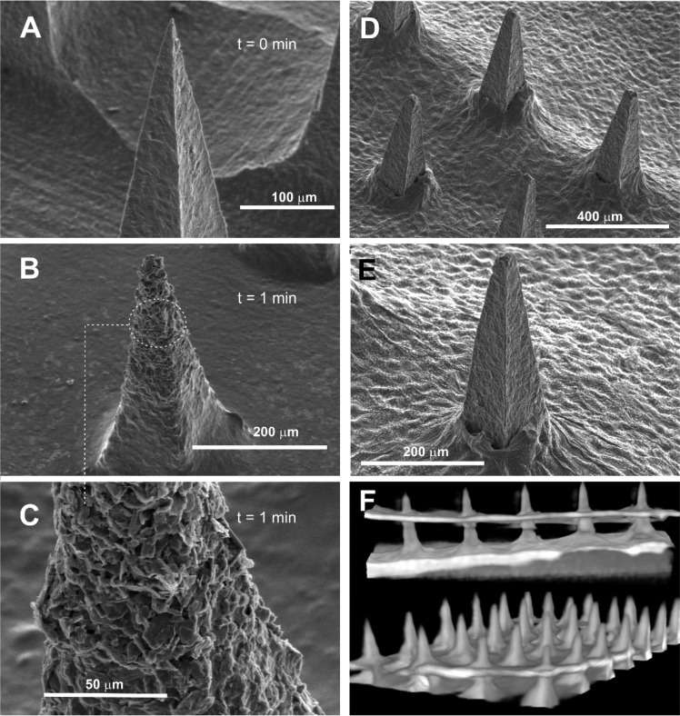
Scanning electron micrographs detailing the structure of an MN array (height: 350 μm) cast from a solution of CAP without any additional components are highlighted in Figure 2A. Well-defined peaks were obtained and were found to be stable in solutions where the pH is acidic/neutral. Upon exposing the CAP MN array to pH 8 buffer, the needle definition deteriorates and gradually dissolves as indicated in the electron micrographs (Figure 2B–D) recorded after 1, 3, and 5 min intervals, respectively.
Figure 2.
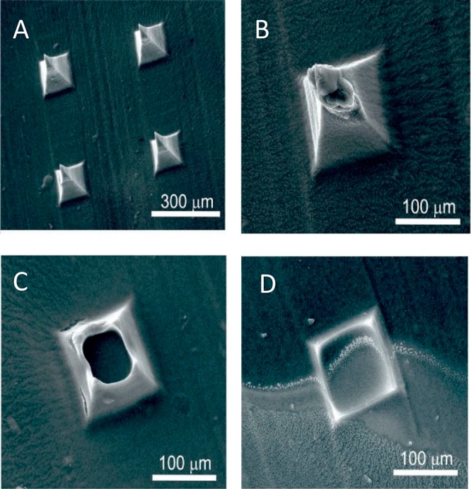
Scanning electron micrographs of the cellulose acetate phthalate microneedles upon exposure to pH 8 Britton–Robinson buffer. Recorded at (A) 0, (B) 1, (C) 3, and (D) 5 min. Microneedles: 200 × 200 × 350 μm.
The process was repeated using the nanocarbon–CAP (C–CAP) formulation, and representative electron micrographs recorded after 1 min in pH 8 BR buffer are detailed in Figure 3A–C. The initial morphology of the composite needle (Figure 3A) is relatively smooth with no pronounced defects or granularity. The latter could have been expected given the particulate nature of the carbon, and such features have been previously observed with palladium systems.13 Upon being immersed in the pH 8 buffer, the CAP layer begins to dissolve (Figure 3B), and while the needle framework is retained, the outer surface begins to transform. The dissolution of the CAP leaves the residual carbon substructure exposing the platelet-like carbon formation (Figure 3C). As the needles are left in contact with the buffer, dissolution of the cap continues and compromises the integrity of the structure, leading to sustained erosion and disappearance of the needles—akin to the behavior observed with the pure cap systems (Figure 2B,C)
Figure 3.
Scanning electron micrographs of the C–CAP microneedles before (A) and after (B) 1 min of exposure to pH 8 Britton–Robinson buffer. Dissolution of the CAP polymer leaving carbon platelets is highlighted in (C). Scanning electron micrographs (D,E) and computerized tomography (F) of microneedles’ piercing of needles through defleshed tomato skin. Microneedle array: 200 × 200 × 700 μm.
The ability of the needles to pierce and retain integrity was assessed through electron microscopy and computerized tomography (CT) of MN arrays puncturing tomato skin. Representative images are shown in Figure 3D–F. The tomato flesh was removed from the cuticle in order to enable inspection of the needles post pierce with the web-like indentations on the skin’s inner surface (Figure 3D,E), characteristic of cell wall structures that remain strongly adherent to the cuticle. The ability to section through the microneedle array using the CT scans also confirmed that the needle structures were solid and free of fissures or voids.
Cyclic voltammograms detailing the response of the carbon–CAP MN array (200 × 200 × 350 μm) to ferrocyanide and ruthenium hexamine (individual solutions containing 2 mM redox probe, 0.1 M KCl, 50 mV/s) are detailed in Figure 4A,B, respectively. In both cases, well-defined peaks are obtained, although there is marked deviation from the ideal peak separations of 59 mV. This can be attributed to the composite nature of the MN array; similar behavior has been observed with the composite Pd–polystyrene microneedle.12 Nevertheless, the ability of the needles to function as viable electrochemical sensors is apparent.
Figure 4.
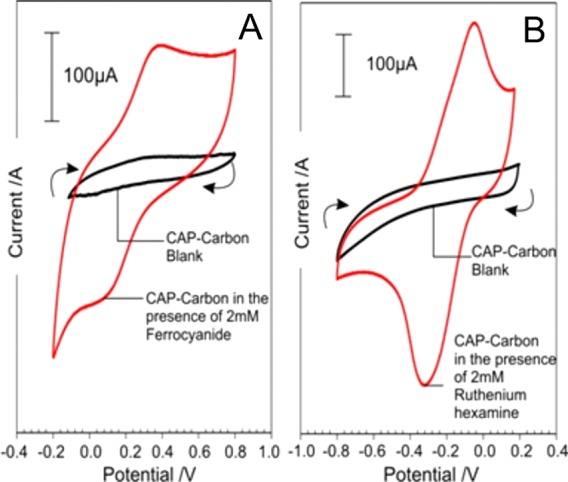
Cyclic voltammograms detailing the response of the C–CAP microneedles to ferrocyanide (A) and ruthenium hexamine (B). Each redox probe present at 2 mM in 0.1 M KCl. Scan rate: 50 mV/s.
Electrochemically Induced Dissolution of CAP
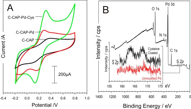
Palladium is widely used to enhance the HER process20,21 and has been employed in the form of clusters and coatings with graphite,22−24 carbon nanotubes,25 graphene,26,27 molybdenum nanosystems,22,28,29 and various metal nanoparticle systems30−32 for use in fuel cell applications. In contrast to most metals and alloys, the dissociation of H2 molecules within Pd structures is facile, occurs with almost no activation barrier, and serves as an ideal catalyst for hydrogen sorption and desorption.33,34 The core approach here, however, is not to utilize the hydrogen being produced but rather to exploit the change in local pH that arises as a consequence of the electrolysis. Given that carbon is a relatively poor substrate for the HER process, it was assumed that the presence of the metallic Pd on the surface would enable a much more effective response. A thin layer of palladium was sputtered on the C–CAP microneedles to assess whether or not the presence of the metal would improve the overall performance—both in terms of sensing application but, more importantly, as a means of enhancing the HER process, which would be required to promote swelling of the needles as indicated in Figure 1. The influence of the Pd layer on the electrode response to ferrocyanide is highlighted in Figure 5A. The addition of the cysteine onto Pd layers was confirmed through XPS analysis and comparison of the S 2p peak before and after modification as indicated in Figure 5B.
Figure 5.
(A) Cyclic voltammograms comparing the responses of the C–CAP and C–CAP–Pd microneedles to 2 mM ferrocyanide before and after modification with palladium and cysteine. Scan rate: 50 mV/s. (B) XPS spectra highlighting the modification of C–CAP–Pd microneedles with cysteine.
The Pd layer was found to improve the electrochemical performance through increasing the electron transfer kinetics as indicated by the improvement in the peak definition and separation; however, the greatest gain in performance was achieved through the further modification of the surface with an adsorbed cysteine layer as described by McFie and Feliciano-Ramos and associated colleagues.35,36 The latter has been attributed to the protonated amino group of the cysteine improving electron transfer from the negatively charged ferrocyanide,36 but it must be noted that modification with 2-mercaptoethansulfonate (presenting a net negative charge at the interface) was equally capable of facilitating ferrocyanide electrochemistry.35 It is likely that the cysteine promoted electrode enhancement is through the removal of the surface oxides at the Pd interface.35
The responses detailed in Figure 5A highlight the benefits of employing Pd–cysteine layers for sensing purposes—where the microneedle array is to be used as both sensor and actuator. It must be noted however that the imposition of the large reducing potential necessary to initiate HER (and hence drug release) would result in the reduction the Pd–thiol bond, leading to the desorption of the cysteine37 such that the latter has little influence on the kinetics of drug release. As such, the cysteine modification step was omitted from the subsequent investigations of microneedle dissolution. Linear sweep voltammograms detailing the response of the MN arrays (C–CAP and C–CAP–Pd) are compared in Figure 6 under two different pH regimes. It is clear that, in both cases, the presence of the Pd has a dramatic impact on the relative responses.
Figure 6.
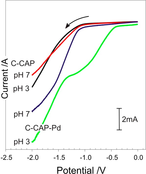
Linear sweep voltammograms of the unmodified and Pd coated microneedles in pH 3 and 7 Britton–Robinson buffer. Scan rate: 50 mV/s.
The next phase was to assess the ability to control the swelling or dissolution of the microneedles. A skin mimic assembly was constructed, in which a calcium alginate gel containing 2 mM ferrocyanide was prepared as previously described.12 The pH was controlled to ensure that the matrix itself did not lead to the dissolution of the needles. A thin layer of parafilm was then stretched over the gel to act as the skin’s stratum corneum. The modified microneedles were then pressed onto the parafilm layer (100 μm) through simple application of thumb pressure with the needle tips piercing through the polymer into the underlying gel. A separate reference electrode (3 M NaCl, Ag|AgCl) and Pt counter were then inserted through the parafilm to complete the cell. Ferrocyanide was included within the gel to acts as an in situ probe that could be used to assess the structural integrity of the microneedle. Voltammograms were recorded before the application of any cathodic potential to serve as a control. It was envisaged that as the imposition of a cathodic potential would increase the pH and lead to the swelling or dissolution of the CAP binder within the core of the needle framework, and as such, the surface area of the needles would change. The latter could therefore be assessed through changes in the peak magnitude of the ferrocyanide within the gel. Thus, the ferrocyanide voltammograms were recorded before and after each cathodic step. Cyclic voltammograms detailing the response of the MN array within the alginate layer before and after the imposition of a potential of −2 V are shown in Figure 7. Before the cathodic potential is applied, the voltammetric response of the MN array to ferrocyanide is consistent with that observed in Figure 5A.
Figure 7.
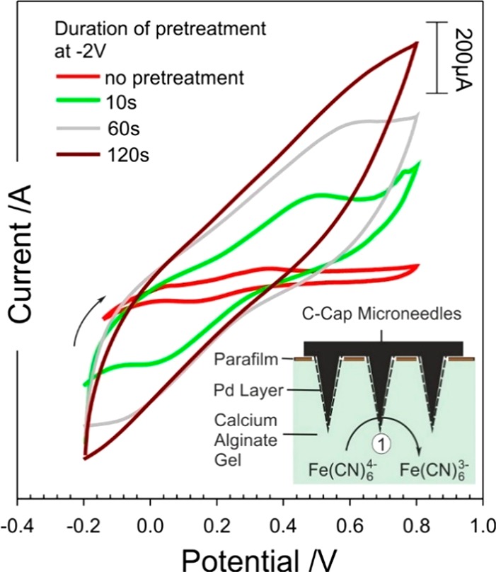
Cyclic voltammograms detailing the response of the C–CAP–Pd microneedles to 2 mM ferrocyanide before and after holding the electrode at −2 V for given time periods.
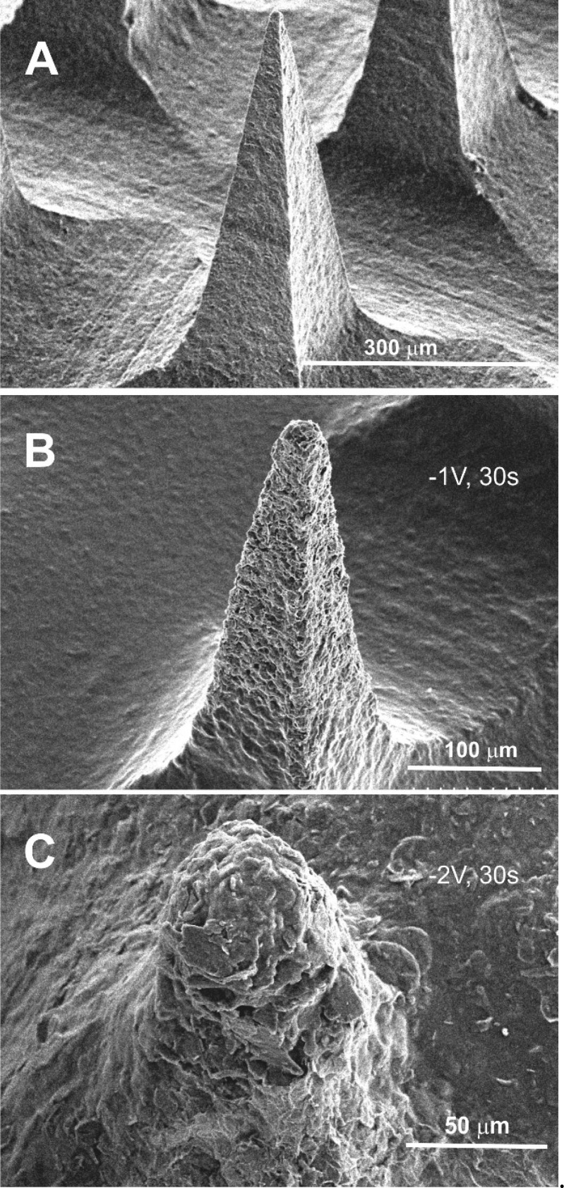
The voltammetric profile changes dramatically upon stimulating hydrogen evolution with a loss of definition. The latter can be attributed to increased resistance within the bulk of the needle structure as a consequence of the binder swelling and increasing the spatial separation between the carbon particles. The swelling and dissolution of the MN were confirmed through placing the array within pH 6 Britton–Robinson buffer (without a barrier layer) and examining the needle morphology after various periods of imposing the cathodic potential (−1 and −2 V). Electron micrographs comparing needle integrity before and after the onset of hydrogen evolution are detailed in Figure 8A–C. The electron micrographs highlight the gradual dissolution of the microneedle structure as the electrode is held at varying potentials (−1 and −2 V) for a period of 30 s. The dissolution of the CAP polymer is noticeable at −1 V with the structure of the needle being analogous to that observed in Figure 3B. The application of −2 V however leads to the near complete removal of the needle after 30 s. However, it is clear from inspecting the cyclic voltammograms (Figure 7) that the resistance increases dramatically upon imposing the reducing potential for very short periods, indicating that swelling occurs relatively readily, but complete dissolution (and degradation of the needle bulk) requires much more forceful conditions. The continued response observed in Figure 7 after the apparent destruction of the needle (as indicated in Figure 8C) is attributed to the continuing electroactivity of the base plate.
Figure 8.
Scanning electron micrographs of the C–CAP–Pd microneedles after the electrode is poised at a reducing potential. (A) Open circuit. (B) −1 V for 30 s. (C) −2 V for 30 s. Microneedle: 200 × 200 × 700 μm.
Electrochemical Release of Model Drug
The efficacy of the electrochemical release method was assessed with a model drug using a gelatin matrix to mimic transport into the skin. The pH of the gelatin was adjusted to pH 4.02, which would prevent the dissolution of the CAP and retain the integrity of the composite microneedle assembly. TBO was chosen as the model drug agent, as it could be easily monitored through visual inspection through a blue coloration (λmax = 630 nm) and could be readily incorporated into the C–CAP formulation. The C–CAP was added to a solution of TBO (5%) in cyclohexanone and stirred until a viscous solution was achieved. It was envisaged that the imposition of the reducing potential at the microneedle array would initiate the HER process and lead to an increase in the local pH. This would induce the dissolution of the CAP, resulting in the release of TBO into the gelatin. To ensure the TBO was released exclusively from the needles, the MN array was first pierced through a layer of parafilm, which acted as a skin mimic, before being placed in the gel in order to separate the baseplate from the gelatin. The TBO containing MN was washed in acid to remove extraneous TBO and then pierced into the gelatin layer and left to sit. No blue coloration was observed, which confirmed that the TBO was entrapped within the MN structure. The effect of imposing the reducing potential is highlighted in Figure 9 where the blue coloration associated with TBO can be seen to develop with duration of the HER electrolysis.
Figure 9.
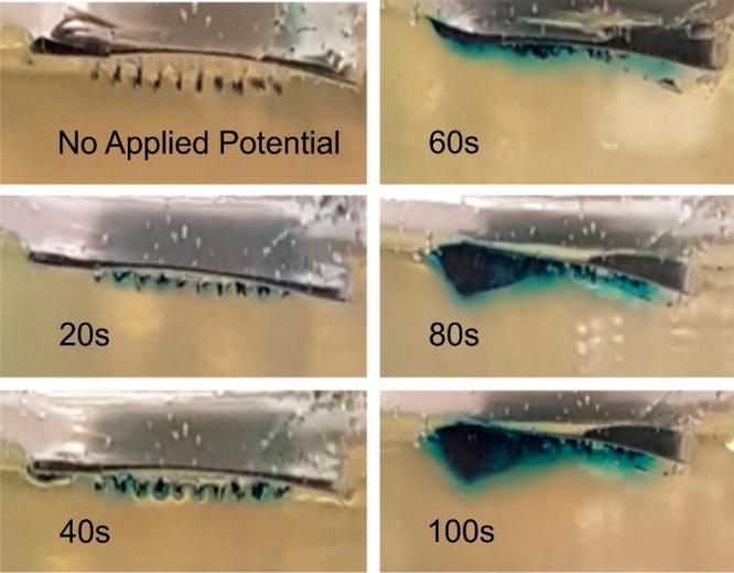
A C–CAP–Pd MN array loaded with TBO and pierced into gelatin (pH 4.02). The imposition of a potential of −2 V over a period of 100 s is shown to affect the release of TBO (blue coloration). Microneedle: 200 × 200 × 700 μm.
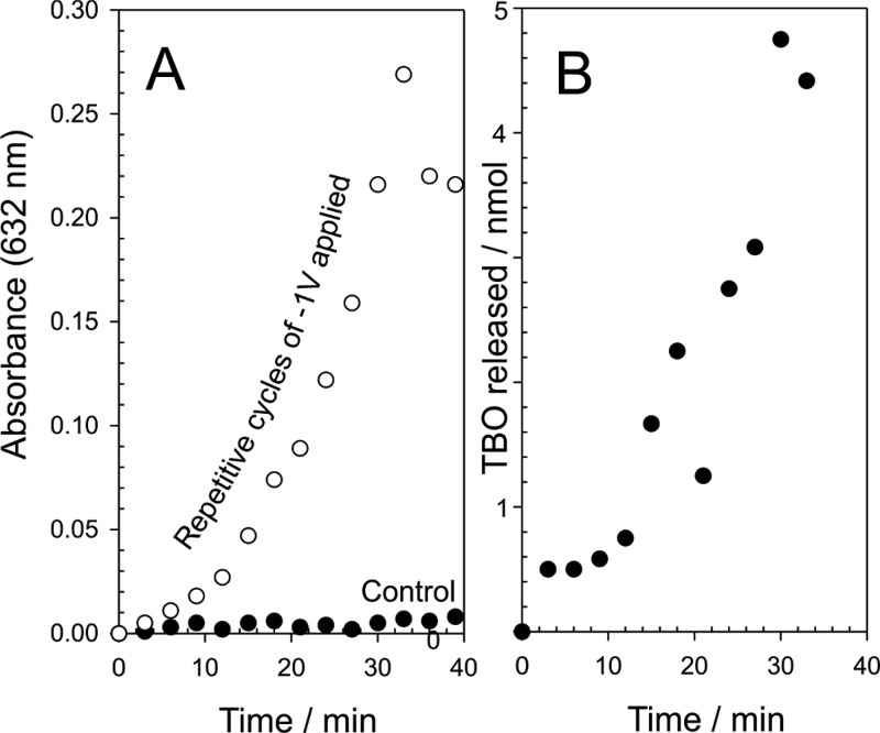
The release of TBO within the gelatin was induced through the application of a large reducing potential (−2 V), which has the effect of rapidly changing the pH at the electrode surface and speeds the dissolution of the CAP component. The prime disadvantage of this approach relates to the fact that the integrity of the needles is rapidly compromised (Figure 8C). A more subtle approach, involving less negative potentials, can also be used (as previously highlighted in Figure 8B). The release of the TBO model drug was further investigated through employing a −1 V release step applied repetitively over a period of 40 min in pH 5 buffer. The microneedle array was held for 3 min at the reducing potential, and thereafter, the solution was sampled and analyzed using conventional colorimetry (TBO λmax = 632 nm; ε = 30 000 M–1 cm–1).38 A control microneedle array containing TBO was left in contact with the buffer without any applied potential, and the results are detailed in Figure 10A. In the absence of an applied potential, there is effectively no release of TBO, whereas the repeated application of −1 V results in sustained release of the model drug. The typical yield per cycle is highlighted in Figure 10B and increases with each cycle before falling dramatically to zero—at which point the needle has effectively dissolved. The yield of drug fall within the nanomole region is as expected given the relatively low capacity of the needles.
Figure 10.
Effect of repetitive application of a potential (−1 V, 300 s) on the release of TBO into pH 5 buffer (A) and the corresponding yield per cycle (B). Microneedle: 200 × 200 × 700 μm.
The micromolding technique clearly provides a facile means of producing high quality microneedles, which, through judicious selection of the casting components, could be applied to a wealth of sensing and drug delivery applications.1−9 The nanocarbon systems are conductive and exhibit reasonable electrochemical properties, which could be harnessed in analytical scenarios. The modification with Pd is easily achieved through employing standard techniques used for coating SEM samples, yet the presence of the metal can provide significant enhancement to the voltammetric performance. The main impact of the work described however relates to the ability to control the integrity of the microneedle through controlling the potential applied at the needles themselves. It is easy to envisage the incorporation of a suitable drug candidate within the carbon–CAP matrix at the time of casting. Drug yield will however be an issue, as it is for many microneedle systems, and it is inevitable that the system proposed here would only be viable for low yield, high potency agents.1−9 The imposition of the reducing potential, although necessary to induce swelling, could also, in principle, lead to the reduction of functional groups within the drug, such as nitro groups, and care would be required to ensure there were no inadvertent modifications to the therapeutic agent as a consequence of the release mechanism. The possibility of fragmentation and the loss of carbon/Pd particulates must also be considered. It must be noted however that, providing the needles are sufficiently shallow, residual needle fragments are liable to be expunged from the skin through normal skin turnover in the outer layers, which would normally occur over a period of weeks.39 The biocompatibility studies of the C–CAP material provide some positive insights into the potential use of the material with no apparent skin irritation nor cytotoxicity; however, these need to be viewed with some caution—particularly where the devices may be used for long-term applications where sensitization may occur.
Conclusions
The electrode potentials used in this work to effect the swelling and dissolution are significantly large and have been selected on the basis of enabling gross characteristics to be observed with relative ease for the purpose of confirming proof of concept. The use of less negative potentials would necessarily reduce the degree of pH modification and, thus, rather than having fairly rapid release, could enable a much more metered dosing without the dramatic deterioration of the needle structure. This would mitigate against issues associated with the loss of nanocarbon/Pd particles into the skin. The approach presented highlights a new route through which microneedle structure could be controlled in situ and thereby offer alternative means of controlling dosage.
Acknowledgments
The authors are pleased to acknowledge financial support from the European Union’s INTERREG VA Programme, managed by the Special EU Programmes Body (SEUPB) and the Department for the Economy (DfE) Northern Ireland.
Author Contributions
The manuscript was written through contributions of all authors. All authors have given approval to the final version of the manuscript. The authors contributed equally.
The authors declare no competing financial interest.
References
- Prausnitz M. R. Microneedles for Transdermal Drug Delivery. Adv. Drug Delivery Rev. 2004, 56, 581–587. 10.1016/j.addr.2003.10.023. [DOI] [PubMed] [Google Scholar]
- Larraneta E.; Lutton R. E. M.; Woolfson A. D.; Donnelly R. F. Microneedle Arrays as Transdermal and Intradermal Drug Delivery Systems: Materials science, manufacture and commercial development. Mater. Sci. Eng., R 2016, 104, 1–32. 10.1016/j.mser.2016.03.001. [DOI] [Google Scholar]
- Cheung K.; Das D. B. Microneedles for Drug Delivery: trends and progress. Drug Delivery 2016, 7544, 1–17. 10.3109/10717544.2014.986309. [DOI] [PubMed] [Google Scholar]
- Tarbox T. N.; Watts A. B.; Cui Z.; Williams R. O. An Update on Coating/Manufacturing Techniques of Microneedles. Drug Delivery Transl. Res. 2018, 8, 1828–1843. 10.1007/s13346-017-0466-4. [DOI] [PubMed] [Google Scholar]
- Pandey P. C.; Shukla S.; Skoog S. A.; Boehm R. D.; Narayan R. D. Current Advancements in Transdermal Biosensing and Targeted Drug Delivery. Sensors 2019, 19 (1–36), 1028. 10.3390/s19051028. [DOI] [PMC free article] [PubMed] [Google Scholar]
- Cheng H.; Liu M.; Du X.; Xu J.; Zhai Y.; Ji J.; He S.; Zhai G. Recent Progress of Micro-needle Formulations: Fabrication Strategies and Delivery Applications. J. Drug Delivery Sci. Technol. 2019, 50, 18–26. 10.1016/j.jddst.2019.01.002. [DOI] [Google Scholar]
- Ita K. Modulation of Transdermal Drug Delivery with Coated Microneedles. J. Drug Delivery Sci. Technol. 2018, 45, 203–212. 10.1016/j.jddst.2018.03.021. [DOI] [Google Scholar]
- Dharadhar S.; Majumdar A.; Dhoble S.; Patravale V. Microneedles for Transdermal Drug Delivery: ASystematic Review. Drug Dev. Ind. Pharm. 2019, 45, 188–201. 10.1080/03639045.2018.1539497. [DOI] [PubMed] [Google Scholar]
- Duarah S.; Sharma M.; Wen J. Recent Advances in Microneedle-Based Drug Delivery: Special Emphasis on its use in PaediatricPopulation. Eur. J. Pharm. Biopharm. 2019, 136, 48–69. 10.1016/j.ejpb.2019.01.005. [DOI] [PubMed] [Google Scholar]
- McConville A.; Hegarty C.; Davis J. Mini-Review: Assessing the Potential Impact of Microneedle Technologies on Home Healthcare Applications. Medicines 2018, 5 (1–15), 50. 10.3390/medicines5020050. [DOI] [PMC free article] [PubMed] [Google Scholar]
- Birchall J. C.; Clemo R.; Anstey A.; John D. N. Microneedles in Clinical Practice-an Exploratory Study into the Opinions of Healthcare Professionals and the Public. Pharm. Res. 2011, 28, 95–106. 10.1007/s11095-010-0101-2. [DOI] [PubMed] [Google Scholar]
- Hegarty C.; McConville A.; McGlynn R. J.; Mariotti D.; Davis J. Design of Composite Microneedle Sensor Systems for the Measurement of Transdermal pH. Mater. Chem. Phys. 2019, 227, 340–346. 10.1016/j.matchemphys.2019.01.052. [DOI] [Google Scholar]
- McConville A.; Davis J. Transdermal Microneedle Sensor Arrays Based on Palladium: Polymer Composites. Electrochem. Commun. 2016, 72, 162–165. 10.1016/j.elecom.2016.09.024. [DOI] [Google Scholar]
- Dasan K. P.; Rekha C. Polymer Blend Microspheres for Controlled Drug Release: The Techniques for Preparation and Characterization: A Review Article. Curr. Drug Delivery 2012, 9, 588–595. 10.2174/156720112803529783. [DOI] [PubMed] [Google Scholar]
- Bertz A.; Wohl-Bruhn S.; Miethe S.; Tiersch B.; Koetz J.; Hust M.; Bunjes H.; Menzel H. Encapsulation of Proteins in Hydrogel Carrier Systems for Controlled Drug Delivery: Influence of Network Structure and Drug Size on Release Rate. J. Biotechnol. 2013, 163, 243–249. 10.1016/j.jbiotec.2012.06.036. [DOI] [PubMed] [Google Scholar]
- Wong C. Y.; Martinez J.; Carnagarin R.; Dass C. R. In-Vitro Evaluation of Enteric Coated Insulin Tablets Containing Absorption Enhancer and Enzyme Inhibitor. J. Pharm. Pharmacol. 2017, 69, 285–294. 10.1111/jphp.12694. [DOI] [PubMed] [Google Scholar]
- Hanafi A.; Nograles N.; Abdullah S.; Shamsudin M. N.; Rosli R. Cellulose Acetate Phthalate Microencapsulation and Delivery of Plasmid DNA to the Intestines. J. Pharm. Sci. 2013, 102, 617–626. 10.1002/jps.23389. [DOI] [PubMed] [Google Scholar]
- Kelley K. E.; Hernandez-Diaz S.; Chaplin E. L.; Hauser R.; Mitchell A. A. Identification of Phthalates in Medications and Dietary Supplement Formulations in the United States and Canada. Environ. Health Perspect. 2012, 120, 379–384. 10.1289/ehp.1103998. [DOI] [PMC free article] [PubMed] [Google Scholar]
- Anderson A.; McConville A.; Davis J. Electrochemical Bubble Rip: A New Approach to Controlled Drug Release. Electrochem. Commun. 2015, 60, 88–91. 10.1016/j.elecom.2015.08.008. [DOI] [Google Scholar]
- Zhang L. L.; Chang Q. W.; Chen H. M.; Shao M. H. Recent Advances in Palladium-Based Electrocatalysts for Fuel Cell Reactions and Hydrogen Evolution Reaction. Nano Energy 2016, 29, 198–219. 10.1016/j.nanoen.2016.02.044. [DOI] [Google Scholar]
- Lin D.; Lasia A. Electrochemical Impedance Study of the Kinetics of Hydrogen Evolution at a Rough Palladium Electrode in Acidic Solution. J. Electroanal. Chem. 2017, 785, 190–195. 10.1016/j.jelechem.2016.12.037. [DOI] [Google Scholar]
- Demir D. D.; Salcı A.; Solmaz R. Preparation, Characterization and Hydrogen Production Performance of MoPdDeposited Carbon Felt/Mo Electrodes. Int. J. Hydrogen Energy 2018, 43, 10530–10539. 10.1016/j.ijhydene.2018.01.030. [DOI] [Google Scholar]
- Asadi S.; Madram A. R.; Biglari E.; Fekri M.; Fotouhi-Far F. Preparation and Study of Electrocatalytic Activity of Ni-Pd(OH)2/C Nanocomposite for Hydrogen Evolution Reaction in Alkaline Solution. Int. J. Hydrogen Energy 2019, 44, 8223–8232. 10.1016/j.ijhydene.2019.01.294. [DOI] [Google Scholar]
- Bhowmik T.; Kundu M. K.; Barman S. Palladium Nanoparticle-Graphitic Carbon Nitride Porous Synergistic Catalyst for Hydrogen Evolution/Oxidation Reactions over a Broad Range of pH and Correlation of Its Catalytic Activity with Measured Hydrogen Binding Energy. ACS Catal. 2016, 6, 1929–1941. 10.1021/acscatal.5b02485. [DOI] [Google Scholar]
- Ramakrishna S. U. B.; Reddy D. S.; Kumar S. S.; Himabindu V. Nitrogen Doped CNTs Supported Palladium Electrocatalyst for Hydrogen Evolution Reaction in PEM Water Electrolyser. Int. J. Hydrogen Energy 2016, 41, 20447–20454. 10.1016/j.ijhydene.2016.08.195. [DOI] [Google Scholar]
- Cardoso J. A. S. B.; Amaral L.; Metin O.; Cardoso D. S. P.; Sevim M.; Sener T.; Sequeira C. A. C.; Santos D. M. F. Reduced Graphene Oxide Assembled Pd-Based Nanoalloys for Hydrogen Evolution Reaction. Int. J. Hydrogen Energy 2017, 42, 3916–3925. 10.1016/j.ijhydene.2016.11.100. [DOI] [Google Scholar]
- Ghasemi S.; Hosseini S. R.; Nabipour S.; Asen P. Palladium Nanoparticles Supported on Graphene as an Efficient Electrocatalyst for Hydrogen Evolution Reaction. Int. J. Hydrogen Energy 2015, 40, 16184–16191. 10.1016/j.ijhydene.2015.09.114. [DOI] [Google Scholar]
- Sharma M. D.; Mahala C.; Basu M. Nanosheets of MoSe2@M (M = Pd and Rh) Function as Widespread pH Tolerable Hydrogen Evolution catalyst. J. Colloid Interface Sci. 2019, 534, 131–141. 10.1016/j.jcis.2018.09.018. [DOI] [PubMed] [Google Scholar]
- Liu X.; Gao S.; Yang P.; Wang B.; Ou J. Z.; Liu Z.; Wang Y. Synergetic Coupling of Pd Nanoparticles and Amorphous MoSToward Highly Efficient Electrocatalytic Hydrogen Evolution Reactions. Applied Materials Today 2018, 13, 158–165. 10.1016/j.apmt.2018.09.001. [DOI] [Google Scholar]
- Jovic B. M.; Jovic V. D.; Brankovic G.; Radovic M.; Krstajic N. V. Hydrogen Evolution in Acid Solution at Pd Electrodeposited onto Ti2AlC. Electrochim. Acta 2017, 224, 571–584. 10.1016/j.electacta.2016.12.015. [DOI] [Google Scholar]
- Zhuang Z. C.; Wang F. F.; Naidu R.; Chen Z. L. Biosynthesis of Pd-Au Alloys on Carbon Fiber Paper: Towards an Eco-Friendly Solution for Catalysts Fabrication. J. Power Sources 2015, 291, 132–137. 10.1016/j.jpowsour.2015.05.023. [DOI] [Google Scholar]
- Zheng L.; Zheng S.; Wei H.; Du L.; Zhu Z.; Chen J.; Yang D. Palladium/Bismuth/Copper Hierarchical Nano-Architectures for Efficient Hydrogen Evolution and Stable Hydrogen Detection. ACS Appl. Mater. Interfaces 2019, 11, 6248–6256. 10.1021/acsami.8b19770. [DOI] [PubMed] [Google Scholar]
- Bartczak W. M.; Stawowska J. Interaction of Dihydrogen with Transition Metal (Pd, Ni, Ag, Cu) Clusters. Struct. Chem. 2004, 15, 447–459. 10.1023/B:STUC.0000037902.93420.28. [DOI] [Google Scholar]
- Nakatsuji H.; Hada M. Interaction of a Hydrogen Molecule with Palladium. J. Am. Chem. Soc. 1985, 107, 8264–8266. 10.1021/ja00312a078. [DOI] [Google Scholar]
- Macfie G.; Simpson L. V.; McColl D.; Cardosi M. F. Mechanism of 2-Mercaptoethanesulphonate Adsorption onto Sputtered Palladium Films: Influence of Surface Oxide Species. J. Phys. Chem. C 2012, 116, 9930–9941. 10.1021/jp2105715. [DOI] [Google Scholar]
- Feliciano-Ramos I.; Caban-Acevedo M.; Aulice Scibioh M.; Cabrera C. R. Self-Assembled Monolayers of L-Cysteine on Palladium Electrodes. J. Electroanal. Chem. 2010, 650, 98–104. 10.1016/j.jelechem.2010.09.001. [DOI] [Google Scholar]
- Li Z.; Chang S.-C.; Williams R. S. Self-Assembly of Alkanethiol Molecules onto Platinum and Platinum Oxide Surfaces. Langmuir 2003, 19, 6744–6749. 10.1021/la034245b. [DOI] [Google Scholar]
- Saha B.; Chowdhury S.; Sanyal D.; Chattopadhyay K.; Suresh Kumar G. Comparative Study of Toluidine Blue O and Methylene Blue Binding to Lysozyme and Their Inhibitory Effects on Protein Aggregation. ACS Omega 2018, 3, 2588–2601. 10.1021/acsomega.7b01991. [DOI] [PMC free article] [PubMed] [Google Scholar]
- Baran R.; Maibach H.. Textbook of Cosmetic Dermatology, 4th ed.; CRC Press: Boca Raton, FL, 2010. [Google Scholar]


