Abstract
Digital silicon photomultiplers (dSiPMs) have potential in the advancement of PET detectors. Their advantages include decreased dark counts through selective microcell activation, fast timing, and flexibility configuring event triggering and collection. Further improvements in PET image resolution are possible when photon depth of interaction (DOI) is available, as this reduces parallax error caused by mispositioning events at the peripheral field of view. These improvements are desirable in smaller ring diameter PET systems, such as whole body PET/MRI. In this study we quantify the DOI capabilities of a unique crystal array design (termed dual light sharing arrays or DLSA) that takes advantage of the 2-by-2-pixel die readout logic of a PDPC dSiPM (Philips Digital Photon Counting 3200) device by Philips Medical Systems.
The DLSA is comprised of a 2×2 array of 4×4×22 mm3 LYSO crystals; inter-crystal surfaces were optically coupled in part with high-index optical adhesive and optically isolated in complimentary parts with mirror-film reflector such that light sharing was depth-dependent and different along two axes. The DLSA was mounted to one die of a PDPC and its depth-dependent response to 511-keV gamma rays was calibrated using a coincidence-collimated beam from both side and entrance surfaces. Entrance surface DOI calibration was performed through an iterative application of maximum likelihood calculations based on the signal ratio in crystals adjacent to the crystal of interaction.
Results showed timing resolutions of 350–370 ps and energy resolutions of 10–12% while achieving a DOI position estimation of 6–7 mm FWHM. Significant improvements in depth estimation error were found when using maximum likelihood estimation and 3–4 depth bins. Furthermore, similar calibration results were obtained for both side-surface and entrance-surface illumination methods, which suggest that PET system calibrations may be easily performed using a monoenergetic flood source with entrance surface illumination.
Index Terms—: Depth of Interaction, Digital Photon Counter, PET, PET Instrumentation
I. Introduction
Recent advances in digital silicon photomultiplier (dSiPM) technology have made it possible to utilize fully digital devices in the development of PET detectors. This technology builds upon earlier analog silicon photomultiplier technology, which has shown to have several advantages over older photomultiplier tube-based methods such as very good timing resolution, DOI capability, and MRI compatibility [1]. Like the analog devices, digital silicon photomultipliers are formed from an array of microscopic Geiger-mode avalanche photodiodes (microcells), which are summed to give a signal proportional to the number of breakdowns. However, an analog device provides the sum of the breakdown-induced current while digital devices output the sum of the binary state of the microcells. Advantages of dSiPMs include decreased dark counts through selective microcell activation, fast timing, and increased flexibility configuring event collection.
Further improvements to PET image resolution are possible when photon depth of interaction (DOI) is available. The initial goal for this study was to achieve a DOI positioning resolution better than twice the width of the discrete crystals. This was based on an approximate effective cross section equal to the crystal width when incoming photons are 30° or less off-axis. Investigators have shown that achieving a DOI positioning resolution of approximately twice the width of the desired image resolution leads to relatively uniform spatial resolution throughout the useful imaging field of view [2]. Depth of interaction positioning capability is especially desirable in systems with a smaller detector ring diameter, such as those designed to fit in an MRI [3].
DOI calibration time can be significantly shortened if it requires only front surface irradiation instead of several irradiations from the side at different beam depths. Calibration time is shortened even further if the look up tables (LUTs) from one crystal array and tile can be normalized and applied to the other arrays/tiles in the PET system.
This study explores the DOI capabilities of dual light sharing arrays (DLSA) composed of discrete crystals coupled to dSiPMs as well as examining both side and entrance surface based DOI calibration methods. Further investigations studied the application of LUTs between different dies and crystal arrays.
II. Materials and Methods
A. Digital Silicon Photomultiplier
The dSiPM utilized in this study was a Philips Digital Photon Counting (PDPC) model 3200 and with two tiles. Each tile had sixteen dies, each with an independent time-to-digital converter (TDC). Each die was composed of four 3.2×3.88 mm2 pixels at a 4 mm pitch, each with 3200 microcells. List mode data reported the number of activated microcells for each pixel. These pixels are further divided into a 2×2 array of subpixels, which are primarily used in the triggering and validation algorithms. The acquisition sequence for events in the PDPC is illustrated in Fig. 1.
Fig. 1.
Flowchart of PDPC event acquisition sequence with approximate time required for each step [4]
The PDPC allows for four possible trigger schemes, with the highest dark count rate and fastest timing at trigger scheme 1, which triggers if any of the four subpixels have an activated microcell and therefore requires only one detected photon to trigger. With the slowest timing and lowest dark count rate, trigger scheme four requires activated microcells in all four microcells, which requires an average of 8.3 photons to trigger. After triggering, events in the PDPC must be validated before entering the signal integration phase of acquisition. There are four possible validation schemes (1, 2, 4, and 8), with scheme 1 requiring only one detected photon, and scheme 8 requiring an average of eleven. However, validation scheme has little effect on the timing resolution, as the event timestamp is determined at the trigger stage. [4]
As mentioned above, one valuable characteristic of the PDPC is the ability to selectively disable microcells with the highest dark count rate. In this study, the 15% of microcells with the highest dark count rates were disabled, which decreased the total dark count rate by more than an order of magnitude. The device was run using trigger scheme 2 and validation scheme 8 in order to further reduce dark counts while maintaining good timing resolution. These settings require photon detection in at least two sub-pixels to trigger, and then photon detections in every row-trigger-line (RTL) of the sub-pixel to validate. An additional setting, RTL refresh, was enabled as it reduces the number of false triggers when using trigger scheme 2 by periodically recharging microcells without requiring a trigger. Another sometimes-useful option in the PDPC is neighbor logic, in which triggers in one die force a trigger in neighboring dies. However, as the detector modules in this study covered only a single die, this setting was turned off. [4]
B. Dual Light Sharing Array (DLSA) Modules
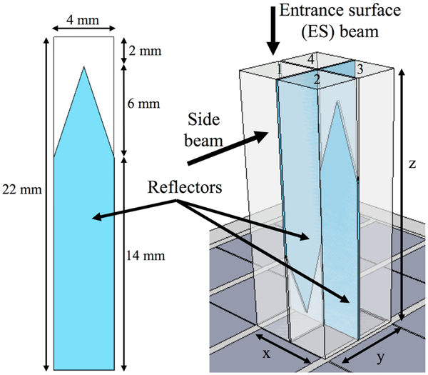
This study focused on measurements made with DLSAs of 4×4×22 mm3 LYSO crystals coupled one-to-one on the four pixels of a single die on a PDPC tile. Earlier studies demonstrated the DOI capabilities and good timing resolution of similar 2×2 arrays [3]. These arrays were designed such that the amount of light shared between the main pixel and its two neighbors varied as a function of depth. This was accomplished by placing mirror film reflectors between meltmount-coupled crystals such that light was shared in one direction near the sensor but in the orthogonal direction at the other end of the array. This sort of depth-dependent light sharing has been shown to allow for good DOI calculation [5]–[7]. Each reflector was 4 mm wide and had a rectangular section (14 mm long) connected to a triangular section (6 mm long) such that light was fully shared for 2 mm, partially shared for 6 mm, and not shared for 14 mm along each crystal surface. The outer surfaces of the DLSA were covered in mirror film and then wrapped in Teflon tape. This DLSA geometry is shown in Fig. 2. In order to quantify effects from neighboring DLSA, some measurements used nine DLSAs combined into a 3×3 grid and separated by mirror film.
Fig. 2.
Geometry of a DLSA with reflector detail (left) and positioning on dSiPM (right). For reference, the crystal numbers, xyz directions, and orientations of entrance surface and side beams are indicated.
C. Measurement Geometry
Events were collected in coincidence (20 ns window) between two PDPC tiles. The coincidence tile was positioned on its side and had a single 4×4×22 mm3 LYSO crystal positioned horizontally, in line with a 60 kBq 68Ge point source such that a ~2 mm diameter beam of coincidence-triggered events are incident on the test crystal surface. This source was positioned 3.2 cm from the coincidence tile surface. The dark box was cooled to 10 °C. In the side irradiation measurements the beam was centered on one of the two front crystals in 2 mm depth increments starting 1 mm from the entrance surface and 20,000 events were collected per beam location. In the entrance surface measurements the test tile was orientated on its side such that the beam was centered on one of the two front crystals and 200,000 events were collected.
Further measurements were completed on both the side and entrance surfaces of the larger 3×3 array of DLSAs. In the side irradiations of this array the geometry was such that the 2 mm diameter beam increased to 2.5 mm in the center DLSAs and 2.8 mm on the rear DLSAs. This variable beam diameter may affect the results, and is one reason why entrance surface calibration is attractive. For the flood irradiation in the entrance surface measurements the 68Ge source was placed ~20 cm away and only singles were collected.
D. Event Processing
List mode data was filtered to remove any events recorded from the wrong PDPC die. An energy window was then applied to the total event energy for which a Gaussian was fit to the test die photopeak and anything outside three standard deviations discarded. The energy window applied to coincidence crystal energy deposition was wider and encompassed the photopeak as well as the top portion of the Compton edge, but not the scatter peak due to scatter in nearby surroundings. For the final filtering step, a Gaussian was fit to the signal from the primary test pixel and three standard deviations were kept, which minimized the number of Compton scatter events in the primary crystal. The events used to test the DOI algorithm were filtered only by total event energy on both tiles and not by primary test pixel energy.
E. DOI Calibration
DOI calculations were based on a maximum likelihood estimation (MLE) method [8]. This method required look up tables (LUTs) of the means and the variances for filtered events at every depth. This was a simple matter in the side calibration, as the true interaction depth was known. Applying a boxcar filter to smooth both of the LUTs further increased performance. However, as the true depth of interaction was unknown in entrance surface measurements, another strategy had to be used.
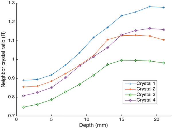
Due to the design of the reflectors detailed in Fig. 1, signal in the x-direction neighbor crystal increases with DOI, while the signal in the other adjacent crystal (y direction) decreases with DOI. Therefore, the ratio of the signals in these two adjacent neighbor crystals (R) is monotonic with depth and may be used as a surrogate for depth once sorted in ascending order. An example of this monotonic behavior is illustrated in Fig. 3 for a case in which depth was known a priori.
Fig. 3.
Neighbor crystal ratio (R) as a function of DOI (side illuminating beam position) for events in all four crystals in an example DLSA
Event positioning for the entrance surface (ES) DOI calibration was done by sorting all events by R and then splitting into bins, each containing the expected number of events for that depth bin. Expected number of events was calculated based on linear attenuation from the entrance surface in LYSO. LUTs were created using the mean and variance of events in each bin. These LUTs were then tested through application to the side calibration data, for which true event DOI was known. True depth was assumed to be at the center of the side illumination beam with no correction for the 2 mm beam diameter. Effective DOI FWHM values were computed using a weighted average based on the linear attenuation of photons from the entrance surface. Although correcting for beam size would improve the estimated spatial resolution, later efforts, as discussed below, resulted in a recommendation of using entrance surface calibration with a flood source. Therefore, this potential improvement is not relevant to future use of the proposed system.
Once event depths were estimated using the MLE algorithm, they were re-binned into depths corresponding to the median position in each of 1–7 depth bins. Average errors were then calculated based on the difference between the binned position and the side beam position in the testing data.
III. Results and Discussion
A. Energy and Timing Resolution
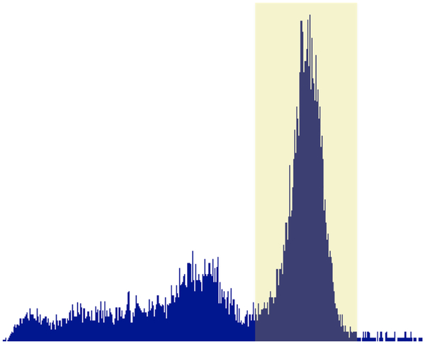
As expected, timing and energy resolution were dependent on interaction depth as well as variations in array manufacture. However, timing resolutions between single DLSAs and single 4×4×22 mm3 LYSO crystals were less than 370 ps and saturation-corrected energy resolutions were all 12–16%. Timing and energy resolution results are detailed in Table I and a sample energy spectrum with highlighted region of interest in Fig 4.
TABLE I.
Timing and Energy Resolutions
| Array Geometry | Energy Resolution | Timing Resolution |
|---|---|---|
| Single DLSA (ES) | 12.9 ± 0.8% | 366 ± 7.3 |
| Single DLSA (side) | 15.2 ± 0.3% | 346 ± 2.3 |
| Nine DLSA array (ES) | 12.6 ± 0.6% | 393 ± 2.2* |
| Nine DLSA array (side) | 16.1 ± 1.7% | 359 ± 4.2 |
| Nine DLSA array (ES flood) | 14.1 ± 0.3% | -- |
Coincidence timing between two DLSAs
Fig. 4.
Sample energy spectrum from side irradiation of single DLSA with highlighted region of interest
B. Depth Resolution Estimation
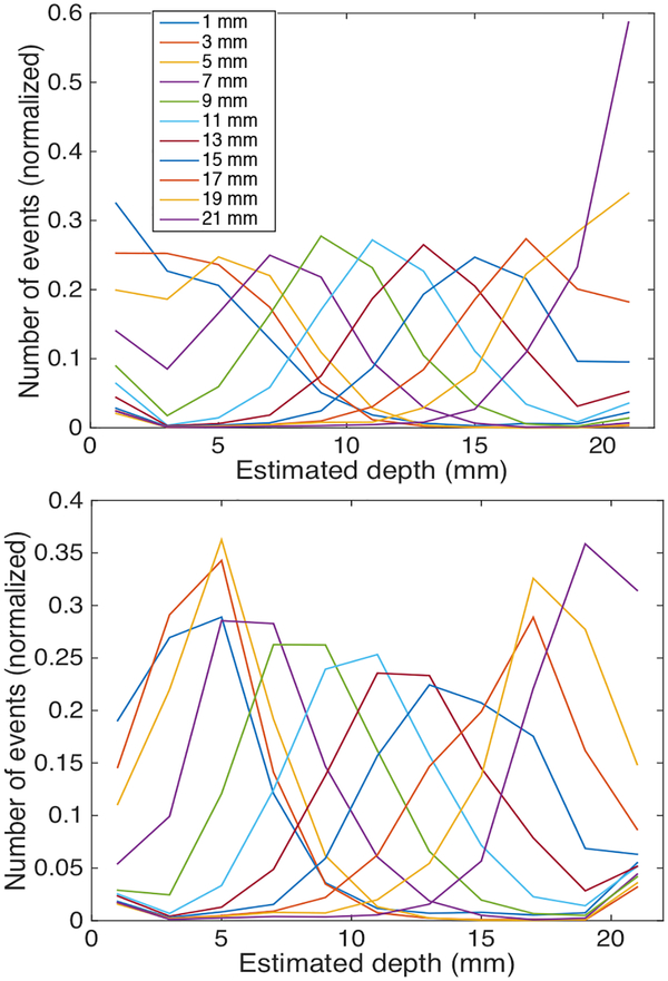
Effective DOI FWHM for both the side and ES calibrations was well within the 8 mm goal for these crystals and ranged from 5.8 mm to 7.2 mm. This is illustrated in the example MLE event placement histograms in Fig. 5. However, as R changes little near either end of the crystals, the ES calibrations showed more bias in these regions, with significant overlap in the MLE histograms, as shown in Fig. 5 (bottom).
Fig. 5.
Sample MLE histograms for side (top) and entrance surface (bottom) calibrations with different beam depths colored
C. DOI Performance
The average errors for side and ES calibrations in both single DLSAs and larger DLSA arrays are shown in Fig. 6. In this figure the single bin results converge to the value expected were the distribution of linearly-attenuated photons placed at the median location in the crystal. Note that the side calibration of nine DLSAs was based on relatively noisy data due to the difficulty in achieving sufficient counts in interior DLSAs because of the attenuation in outer DLSAs. The data from these inner DLSAs was included in the average error calculations because the error introduced by Compton scatter in neighbor DLSAs must be considered. Although error estimation in the side calibration could be improved with longer calibration time, entrance surface calibration works just as well (see single DLSA) and is much faster.
Fig. 6.
Average error as a function of number of depth bins
As predicted based on the MLE histogram FWHM values shown in Fig. 5, significant improvement was observed when using 3–4 depth bins, with little advantage to finer binning. Furthermore, ES calibrations, which are much more easily achieved in PET systems, increase the average error by only about 0.3 mm compared to side calibrations when using 3–4 depth bins. Efforts exploring the robustness of the calibration methods found that ES calibrations required only ~5000 energy filtered events per crystal when the same arrays were used for testing and calibration. Initial applications of LUTs from one DLSA to another showed that while the DOI calibration is dependent on crystal placement and individual DLSA, depth placement was possible once the LUTs were normalized by their respective average and variance of ES signals. In these initial measurements the effective FWHM increased by approximately 3% and the effective root mean square (RMS) error by 6% when using renormalized LUTs from another DLSA. However, these comparisons were based on single DLSAs and neglected the contribution due to Compton scatter from neighbors. Because it is both difficult to collect enough counts in interior DLSAs for accurate LUTs, and results from the ES calibrations using a flood source are promising, it is not necessary to pursue this type of LUT standardization.
IV. Conclusions
The DOI capabilities and two calibration techniques of unique dual light sharing 2×2 arrays (DLSA) of 4×4×22 mm3 LYSO crystals on the PDPC have been investigated. Timing resolution was good at 350–370 ps. DOI position estimation of 6–7 mm FWHM was well within the 8 mm goal for these crystals in both side and entrance surface calibration methods. Significant improvements in depth estimation error were found when using 3–4 depth bins, with little further gains in finer binning. It has been shown that eventual PET systems utilizing DLSAs and digital silicon photomultipliers may be easily calibrated using a monoenergetic flood source on the detectors’ entrance surface and achieve average depth positioning error of less than 3.5 mm.
Acknowledgments
This work was supported in part through a research contract with Philips Healthcare, NCI CA136569, and NIBIB EB002117.
V. REFERENCES
- [1].Del Guerra A, Belcari N, Giuseppina Bisogni M, LLosa G, Marcatili S, Ambrosi G, Corsi F, Marzocca C, Dalla Betta G, and Piemonte C. (2010). Advantages and pitfalls of the silicon photomultiplier (SiPM) as photodetector for the next generation of PET scanners. Nucl. Inst. and Meth. in Phys. Res. A 617, pp. 223–226. [Google Scholar]
- [2].Yang Y, Wu Y, Qi J, St. James S, Du H, Dokhale PA, Shah KS, Farrell R, Cherry S. (2008). A Prototype PET Scanner with DOI-Encoding Detectors. J. Nucl. Med 49, pp. 1132–1140. [DOI] [PMC free article] [PubMed] [Google Scholar]
- [3].Lehnert AL, Hunter WCJ, Lewellen TK, Miyaoka RS. (2013). Evaluation of depth of interaction measurements using discrete crystal arrays and digital silicon photomultipliers. Presented at IEEE Nuclear Science Symposium and Medical Imaging Seoul, South Korea M11–25 [Google Scholar]
- [4].Philips Digital Photon Counting, PDPC-TEK-Manual (v0.21), 2013.
- [5].Lewellen TK, Macdonald LR, Miyaoka RS, McDougald W, Champley K. (2007). New Directions for dMiCE - a Depth-of-Interaction Detector Design for PET Scanners. IEEE Nuclear Science Symposium Conference Record 5, pp. 3798–3802. [DOI] [PMC free article] [PubMed] [Google Scholar]
- [6].Lewellen TK, Janes ML, Miyaoka RS. (2004). DMiCE – A Depth-of-Interaction Detector Design for PET Scanners. IEEE Nuclear Science Symposium and Medical Imaging, pp. 2388–2392. [DOI] [PMC free article] [PubMed] [Google Scholar]
- [7].Ito M, Lee MS, Lee JS. (2013). Continuous depth of interaction measurement in a single-layer pixelated crystal array using a single-ended readout. Phys Med Biol. 58, pp. 1269–1282. [DOI] [PubMed] [Google Scholar]
- [8].Ling T, Lewellen TK, Miyaoka RS. (2007). Depth of interaction decoding of a continuous crystal detector module. Phys. Med. Biol 52, pp. 2213–2228. [DOI] [PubMed] [Google Scholar]


