

Abstract
It is shown, quantum chemically, how structural distortion of an aromatic dye molecule can be leveraged to rationally tune its optoelectronic properties. By using a quantitative Kohn–Sham molecular orbital (KS‐MO) approach, in combination with time‐dependent DFT (TD‐DFT), the influence of various structural and electronic tuning parameters on the HOMO–LUMO gap of a benzenoid model dye have been investigated. These parameters include 1) out‐of‐plane bending of the aromatic core, 2) bending of the bridge with respect to the core, 3) the nature of the bridge itself, and 4) π–π stacking. The study reveals the coupling of multiple structural distortions as a function of bridge length and number of bridges in benzene to be chiefly responsible for a decreased HOMO–LUMO gap, and consequently, red‐shifting of the absorption wavelength associated with the lowest singlet excitation (λ≈560 nm) in the model cyclophane systems. These physical insights together with a rational approach for tuning the oscillator strength were leveraged for the proof‐of‐concept design of an intense near‐infrared (NIR) absorbing cyclophane dye at λ=785 nm. This design may contribute to a new class of distortion‐controlled NIR absorbing organic dye molecules.
Keywords: cyclophanes, density functional calculations, dyes/pigments, HOMO–LUMO gap, near-infrared absorptions
How low can you go? Various modes of structural distortion are systematically studied and the findings are used to rationally tune the HOMO–LUMO gap and oscillator strength to furnish a bright distortion‐controlled near‐infrared (NIR) absorbing organic dye by using benzene as a model system.
Translation abstract

Introduction
Modulation of frontier orbital energies has elucidated many aspects of materials and synthetic chemistry. Illustrative is the aspect of decreasing the HOMO–LUMO gap (ΔE H‐L), which has found widespread applications in solar cell design,1 long‐wavelength absorbing photosensitizers,2 near‐infrared (NIR) fluorophores in bioimaging of deep tissues,3 and NIR emitters in organic electronics.4 Decreasing the ΔE H‐L in organic compounds has been attributed to extending π conjugation,5 enhancing planarity,6 or adding donor–acceptor motifs7 to conjugated structures (see Scheme 1). By quantifying their interplay in the ΔE H‐L, we recently developed design principles for NIR absorbing dyes.8 Despite the fact that the abovementioned concepts are all efficient in decreasing the ΔE H‐L, there is still a lack of design concepts and a systematic framework to rationalize such concepts. Therefore, we aim to utilize the concept of structural distortion as a tool to modulate the ΔE H‐L in pursuit of the rational design of intense NIR absorbing organic dyes.
Scheme 1.
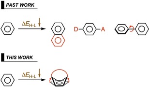
Previous approaches (top)5, 6, 7 and our proposed distortion‐controlled approach (bottom) for decreasing and tuning the HOMO–LUMO gap in organic dye molecules. D = donor, A = acceptor.
By controlling the distortion of aromatic π systems, their electronic structure can be tuned (see Scheme 1). We have already shown that incorporating a heavy heteroatom into the aromatic core of benzene (YC5H6; Y = Si, Ge, P) decreases the ΔE H‐L due to in‐plane structural distortion, which causes a redshift in the lowest excitation.8 We further showed that distortion into a boat‐like conformation accelerated the Diels–Alder cycloaddition, relative to that of benzene (1).9 A related example concerns hoop‐shaped benzene rings, of which the para positions are covalently connected.10 Reducing the number of benzene rings (n) decreases the hoop size of these [n]cycloparaphenylenes and results in smaller ΔE H‐L values; this has been attributed to enhanced conjugation among the neighboring π orbitals due to a decrease in torsional angles. Recently, structural distortion of a Sm@C88 carbon cage was found to affect the ΔE H‐L.11 With increased pressure, the ΔE H‐L becomes smaller as the cage is distorted from its equilibrium ellipsoid shape to spherical, to peanut‐shaped, followed by eventual collapse. Other carbon nanostructures have shown similar behavior.12 There are also extensive studies on distorted porphyrin rings that exhibit red‐shift compared with their planar counterparts.13 Collectively, these studies suggest a causal relationship between increased structural distortion and decreased ΔE H‐L, and therefore, a sound rationalization of the effect of controlled distortion on ΔE H‐L is warranted.
Cyclophanes,14, 15, 16, 17 with their strained benzene rings, are ideal candidates to enhance our understanding of the influence of structural distortion on electronic properties. Increased strain in the cyclophane is known to decrease its ΔE H‐L, thereby red‐shifting the absorption spectrum,18 but the underlying mechanism is far from trivial. Recently, we delineated this relationship by bending benzene into a boat conformation to examine the Diels–Alder reactivity of [5]cyclophanes.9 Herein, we expand the insights gained from the reactivity study toward tuning of the optoelectronic structure. The focus is on how distortion of the benzenoid core controls the modulation of ΔE H‐L and how it can be leveraged to rationally design a distortion‐controlled NIR absorbing organic dye. In addition to the proper absorption wavelength, a large oscillator strength is fundamental for the efficacy of a NIR chromophore. Therefore, we also undertake a rational approach to tune the oscillator strength. In addressing these questions, we explore the effect of π–π stacking, heteroatom functionalization, and donor–acceptor architectures on the electronic and optoelectronic properties. We use a fragment‐based approach to obtain mechanistic insights into the decrease of ΔE H‐L upon subsequent introduction of various modes of structural distortion. The novelty of the present work is contained not only in the concrete applications, but in the fact that we combine various distortion‐based tuning handles for tuning both the excitation energy and the oscillator strength, and trace the underlying physics, such that the emerging insights can be applied in rational design. All calculations have been performed by using the Amsterdam Density Functional (ADF) 2017 quantum chemistry package developed by SCM19 and the optimized structures have been illustrated by CYLview.20
Computational Details
Structure optimization
The electronic ground‐state geometry optimizations were performed with the dispersion‐corrected GGA‐BLYP‐D3(BJ) functional,21 in combination with the TZ2P22 Slater‐type basis set and a small frozen core. The BLYP‐D3(BJ) functional has been shown to satisfactorily reproduce the structural parameters of stacked systems.21 Scalar‐relativistic effects were included by using the scalar zeroth‐order regular approximation (ZORA).23 All model and benchmark molecules exhibit (local) energy minima, as confirmed by vibrational analysis to have zero imaginary frequencies.
Kohn–Sham molecular orbital (KS‐MO) analysis
KS‐MO24 analyses have been performed at the same level of theory by using the all‐electron TZ2P basis set (i.e., no frozen core approximation). To uncouple the effect of different structural distortions from each other, we performed KS‐MO analyses on unrelaxed structures. Our quantitative molecular orbital interaction analyses, based on fragments, provides accurate and detailed insights into and easy‐to‐interpret models of the response of the electronic structure towards structural and electronic perturbations.
Atomic Voronoi overlap (AVO)
To assess more quantitatively in which part of the molecule overlap arises between the fragment molecular orbitals (FMOs) that constitute the pertinent overall molecule orbital, we present the concept and method of the AVO, which has been inspired by the concept of Voronoi deformation density (VDD) atomic charges.25 The AVO S A,ij AVO on atom A is computed as the numerical integral of the overlap density ρ ij(r) between FMO ϕ i(r) on fragment I and FMO ϕ j(r) on fragment J [Eq. (1)] in the volume of the Voronoi cell of atom A [Eq. (2)], which is defined as the compartment of space bound by the bond mid‐planes perpendicular to all bond axes between nucleus A and its neighboring nuclei, that is, the region in real space that is closer to a particular nucleus than to any other nucleus (c.f., the Wigner–Seitz cells in crystals). The computations have been carried out with ADF and the associated tool DENSF.19
| (1) |
| (2) |
The interpretation of the AVO is straightforward and transparent: S A,ij AVO constitutes that part of the overlap, S ij=∫ϕ i(r)ϕ j(r)dr, that arises in the Voronoi cell of atom A. Equivalently, it can be considered as the amount of charge associated with the overlap density, ρ ij(r), located in Voronoi cell A.
Benchmark and excited‐state calculations
Linear response time‐dependent density functional theory (TD‐DFT),26 within its adiabatic framework, has become the primary tool to simulate excited states of small‐ to medium‐sized molecules.27 Despite its general applicability, there are instances in which it can fail to accurately describe the excited‐state properties of low‐lying ππ* states. For example, TD‐DFT may yield an imbalanced description of the two lowest singlet states of our reference model system benzene 1 (oligoacenes, in general).28 Therefore, a benchmark study was carried out to select the appropriate TD‐DFT functional among the hybrid PBE0,29 the meta‐hybrid M06‐2X,30 and the range‐separated hybrid (RSH) functional CAMY‐B3LYP31 to reproduce the experimentally measured λ max (for details, see Section S1 and Table S1 in the Supporting Information). CAMY‐B3LYP emerged as the best candidate in terms of accuracy (mean absolute deviation (MAD) relative to λ max = 0.39 eV) and systematic consistency (R 2=0.99), in line with a study by Jacquemin and co‐workers.32 Recent studies by Hopf and co‐workers also highlighted the accuracy of RSH functionals to accurately reproduce the absorption spectra of cyclophanes.33 Furthermore, it is known that RSH functionals improve the long‐range asymptotic behavior of the exchange‐correlation potential, enabling them to accurately compute strong charge‐transfer excitations compared to other standard TD‐DFT functionals.34 Compounds 7′ and 7′′ (see Figure S1 in the Supporting Information) are representative examples of charge‐transfer‐based excitation, for which we observe that CAMY‐B3LYP (MAD=0.12 eV) is more accurate than M06‐2X (MAD≈0.22 eV). Benchmark studies by Tozer et al. showed that local excitations were also well reproduced by RSH functionals.35 In light of the highly delocalized and charge‐transfer model systems investigated in our study, we have selected CAMY‐B3LYP as the appropriate TD‐DFT functional, in combination with the TZ2P basis set for obtaining accurate and reliable trends. All electrons are treated variationally (no frozen core), whereas scalar‐relativistic effects are considered through the ZORA formalism. All of the calculations of model systems have been performed in vacuum to remove the solvatochromic effect on the absorption spectra. An additional TD‐DFT calculation was performed on only 18 (see Figure 7) with the nonequilibrium continuum solvation model COSMO36 in the linear‐response framework by using CH2Cl2 (DCM) as the solvent. Hereafter, we denote the S1←S0 excitation energy as E 0(S1), which is composed of a predominant HOMO→LUMO excitation (Table S2 in the Supporting Information), except for 1–4 and 9, in which S2←S0 excitation matches the nature of S1←S0 excitation, and thus, E 0(S2) is discussed for a fair comparison.
Figure 7.
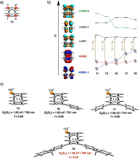
a) Atom numbering of C atoms (red filled circles) in 11. b) Five frontier orbitals (HOMO−1, HOMO, LUMO, LUMO+1, and LUMO+2) of 9, along with the shift in MO ordering, moving from model system 11 to 13 and 16–18, together with the S1←S0 transition [in brown, see also the text and Eqs. (3) and (4)]. c) Photophysical data of model systems 13 and 16–18 (out‐of‐plane bending of the aromatic core α in ° and the inter‐core distance in Å) computed at the CAMY‐B3LYP/TZ2P//BLYP‐D3(BJ)/TZ2P level.
Results and Discussion
The paper is organized as follows. The first section outlines the individual roles of various tuning parameters on the ΔE H‐L value of 1 (see Scheme 2), namely, 1) out‐of‐plane bending of the aromatic core (α), 2) bending of the cyclophane bridge with respect to the aromatic core (β), 3) electronic nature of the bridge (X), 4) stacking of the π‐conjugated cores, and 5) inter‐core distance (d). All mechanistic studies have been performed on benzene model systems with the aim of understanding and quantifying the effects of the aforementioned structural and electronic tuning parameters on ΔE H‐L. The results are illustrated in Figures 1–4. The second section investigates a series of small cyclophane systems to understand the relationship between the tuning parameters (1–5) and ΔE H‐L. Then, we combine all of our findings for the design of more complex cyclophane‐based model systems and rationally engineer a NIR absorbing cyclophane‐like organic dye molecule. The TD‐DFT results of the target system are presented in Figure 5 and Table 1. We conclude the study by tuning the oscillator strength of the lowest singlet excitation. The framework that emerges explains the decrease of ΔE H‐L upon increased structural distortion and can serve as a tool to design novel dyes with tailored optical properties, which is illustrated for a distortion‐controlled NIR absorbing cyclophane.
Scheme 2.
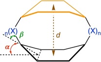
Schematic illustration denoting the various structural and electronic parameters studied systematically in benzene (ring in black): out‐of‐plane bending (α in red), bending of the bridge with respect to the core (β in green), bridge substituent (X in blue), stacking with another π core (in orange), and inter‐core distance (d in brown).
Figure 1.
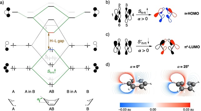
a) Schematic π‐FMO interaction diagram between two equivalent C3H3 quartet triradical fragments based on quantitative KS‐MO analysis depicting the effect of out‐of‐plane bending (α) on ΔE H‐L, in comparison with flat benzene (in gray). Schematic representation of b) different modes of S π–π between allylic π‐HOMOs and c) S′π–π between allylic π*‐LUMOs. d) Side view of the allylic π*‐LUMO wave function plotted on a cut plane through the [H‐C1⋅⋅⋅C4‐H] moiety and perpendicular to the planes of the two allylic fragments (−0.03–0.03 au range). The contour of only one allylic π*‐LUMO is plotted for clarity; the other is symmetrical.
Figure 4.
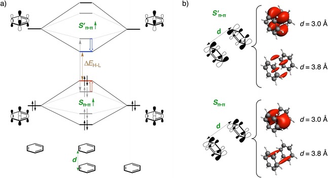
a) Schematic π‐FMO interaction diagram based on quantitative KS‐MO analysis depicting the effect of stacking with another π system (in gray dotted lines) and the effect of decreasing the inter‐core distance (d, in black solid lines) on ΔE H‐L. b) Variation of overlap density, plotted at isovalue = ±0.0004 au, with changes in d between the π*‐LUMO FMOs (S′π–π, top panel) and π‐HOMO FMOs (S π–π, bottom panel) of the closed‐shell C6H6 fragments.
Figure 5.
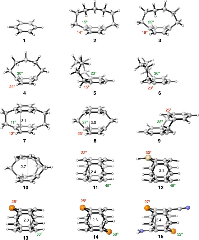
Equilibrium structures of model cyclophane systems (out‐of‐plane bending and bending of the bridge, α (in red) and β (in green), respectively, in ° and inter‐core distance, d, in Å) analyzed in this study. C: gray, H: white, Si: gold, P: orange, N: blue. Only the maximum α and β (see Scheme 1) and minimum d (see Scheme 1) are illustrated for each molecule to ensure a consistent comparison, except 10, in which the average inter‐core distance is mentioned. α and β are not assigned in 10 because they are not congruent with the definitions in Scheme 1.
Table 1.
Orbital energy (H=HOMO, L=LUMO) and ΔE H‐L gap, first and second lowest singlet excitation energies (E 0(S1) and E 0(S2)), along with the oscillator strength (f) corresponding to the S1←S0 transition for the model cyclophane systems.[a]
|
Compound |
H[b] |
L[b] |
ΔE H‐L [b] |
E 0(S1)[c] |
E 0(S2)[c] |
E 0(S1) [nm][c] |
f [c] |
|---|---|---|---|---|---|---|---|
|
1 |
−6.1 |
−1.1 |
5.0 |
5.46 |
6.18 HL |
227 |
0.000 |
|
2 |
−5.3 |
−1.2 |
4.1 |
4.91 |
5.36 HL |
253 |
0.004 |
|
3 |
−5.3 |
−1.3 |
4.0 |
4.69 |
4.98 HL |
264 |
0.005 |
|
4 |
−4.8 |
−1.6 |
3.2 |
4.38 |
4.42 HL |
283 |
0.007 |
|
5 |
−5.5 |
−1.1 |
4.4 |
4.96 HL |
5.65 |
250 |
0.009 |
|
6 |
−5.3 |
−1.3 |
4.0 |
4.55 HL |
5.34 |
272 |
0.010 |
|
7 |
−5.2 |
−1.5 |
3.7 |
4.41 HL |
4.83 |
281 |
0.000 |
|
8 |
−4.8 |
−2.6 |
2.2 |
2.96 HL |
3.37 |
419 |
0.000 |
|
9 |
−5.1 |
−2.0 |
3.1 |
4.06 |
4.20 HL |
305 |
0.000 |
|
10 |
−4.8 |
−2.8 |
2.0 |
2.77 HL |
3.39 |
448 |
0.002 |
|
11 |
−4.8 |
−3.4 |
1.4 |
1.98 HL |
2.99 |
626 |
0.000 |
|
12 |
−4.7 |
−3.7 |
1.0 |
1.70 HL |
1.85 |
729 |
0.000 |
|
13 |
−4.9 |
−3.9 |
1.0 |
1.62 HL |
2.09 |
765 |
0.000 |
|
14 |
−5.0 |
−4.0 |
1.0 |
1.60 HL |
1.75 |
775 |
0.000 |
|
15 |
−4.9 |
−4.1 |
0.8 |
1.45 HL |
1.54 |
855 |
0.008 |
[a] Energies (in eV, unless stated otherwise). [b] Computed at the BLYP‐D3(BJ)/TZ2P level. [c] Computed at the CAMY‐B3LYP/TZ2P//BLYP‐D3(BJ)/TZ2P level. See Table S2 in the Supporting Information for details on the MO composition. The excitation energy corresponding to a HOMO→LUMO transition is marked by HL.
Role of various tuning parameters
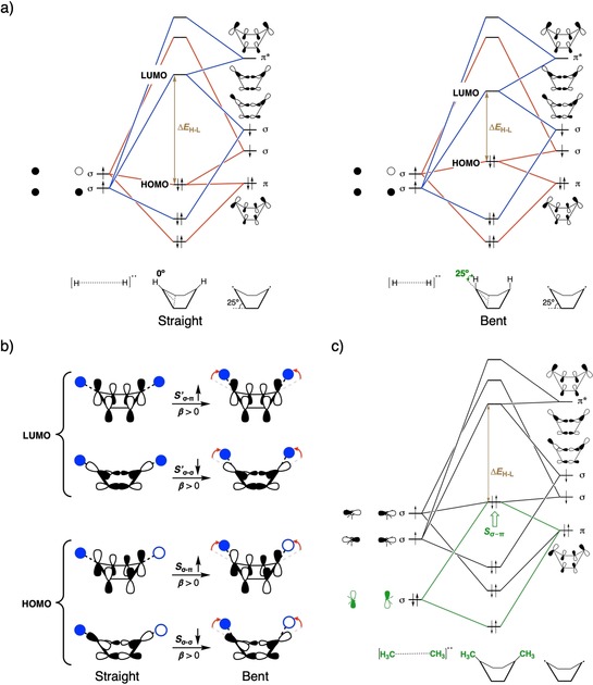
Out‐of‐plane bending (α)
Out‐of‐plane (boat‐like) bending eliminates the degeneracy of the frontier orbitals of benzene as the symmetry is reduced from D 6h to C 2v (see Figure S3 in the Supporting Information). Upon increasing α from 0 to 40°, the π‐HOMO is destabilized, whereas the π*‐LUMO is stabilized, leading to a decrease in ΔE H‐L. A more detailed explanation and analysis are given than that previously reported.9 It starts by combining two allylic C3H3 triradical fragments to form the two σ bonds and one π bond of 1 (Figure 1 a). Bending destabilizes π‐HOMO as the antibonding interaction increases between the two allylic π‐HOMO FMOs, whereas the π*‐LUMO is stabilized due to a favorable interaction between the π*‐LUMO of one allylic fragment and the nuclei of the other. Increasing α from 0 to 25° enhances the antibonding interaction due to an increase in overlap between the allylic π‐HOMOs (S π–π; Table S3 in the Supporting Information). Figure 1 b schematically depicts this increase in overlap to originate from 1) a favorable spatial orientation, leading to a larger through‐bond overlap of the pπ lobes of the allylic π‐HOMO on C2 and C3 (similarly for C6 and C5); and 2) a larger through‐space overlap between the far‐lying pπ lobes on the terminal C1 and C4 atoms (see Figure 1 b for atom numbering) due to a decrease in the C1⋅⋅⋅C4 distance from 2.80 to 2.68 Å. To quantify the extent to which these different modes of overlap contribute to the total overlap, we use the AVO method, which identifies the overlap between two FMOs in the Voronoi cell of a particular atom. For α=25°, the AVO for the C1 and C4 atoms is significant, 0.022 each (25 % of π–π overlap, S π–π; Figure 2 c), upon forming the π‐HOMO. Counterintuitively, the overlap between the allylic π*‐LUMOs (S′π–π, depicted in red in Figure 2 c) decreases upon bending (see Table S3 in the Supporting Information) as the in‐phase overlap (S′π–π depicted in pink in Figure 2 c) is compounded by the out‐of‐phase overlap (S′π–π depicted in green in Figure 2 c) as illustrated in Figure 1 c. The pronounced lowering in energy of the π*‐LUMO of benzene is caused primarily by the stabilization of the two allylic π*‐LUMOs due to the positive potential that one diffuse FMO experiences upon penetrating the nuclei of the other fragment (see Figure 1 a and Table S4 in the Supporting Information). This phenomenon of stabilizing interactions upon spatial proximity of molecular fragments, popularly referred to as charge penetration,37 is well established for bonding in nonpolar molecules.24a, 38 The extent of this effect is evident upon plotting the contours of the allylic π*‐LUMOs wave functions for the flat and bent geometries (Figure 1 d). If α=25°, the π*‐LUMO of one allylic fragment penetrates more into the nuclei of the other (faint blue contour lines crossing the C4 nuclei, see Figure 1 c), relative to planar benzene (same holds for the other allylic π*‐LUMO). These small‐amplitude contour lines penetrating the C4 (or C1) nucleus of one allylic fragment stem from the bent pπ orbitals on C2 (or C3) and C6 (or C5) of the other fragment.
Figure 2.
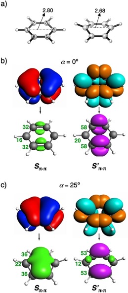
a) Atom numbering and the C1⋅⋅⋅C4 distance (in Å) for α=0° (left) and α=25° (right). Overlap density between the π‐HOMOs (S π–π) and the π*‐LUMOs (S′ π–π) of the two allylic fragments from which benzene can be constructed for b) 0° and c) 25° out‐of‐plane bending of benzene (isovalue = ±0.002 au). Pink and green isosurfaces indicate positive and negative phases, respectively. AVOs (in milli‐au) are shown in bold dark green for each atom beside the overlap density. Isosurfaces of the allylic π‐HOMO/π*‐LUMO that give rise to the overlap density are shown on top of the single‐headed arrow (isovalue = ±0.05 au).
The large change in electronic structure upon bending, specifically in the context of a smaller ΔE H‐L, has a direct impact on the photophysical properties. An increase in α from 0 to 40° redshifts E 0(S1) by nearly 1.20 eV (see Table S5 in the Supporting Information). Interestingly, in all cases, except if α=40°, the S1←S0 transition is composed of two singly excited configurations, HOMO→LUMO+1 and HOMO−1→LUMO, and all of them exhibit zero oscillator strength. However, if α=40°, the large decrease in ΔE H‐L changes the nature of the lowest singlet excitation to a predominant HOMO→LUMO transition, with an increased oscillator strength from 0.00 to 0.04 (see Table S5 in the Supporting Information).
Bending the bridge (β)
The structural deformation of benzene can also be accomplished by bending of the cyclophane bridge, β, to induce a decrease in the ΔE H‐L (Figure 3 a and Figure S5 in the Supporting Information), in accordance with our study on aromatic Diels–Alder reactions.9 The effect can be analyzed by considering the interaction between [H⋅⋅⋅H]: and [C6H4]: triplet diradical fragments to form benzene.
Figure 3.
a) Schematic FMO interaction diagram based on quantitative KS‐MO analysis between [H⋅⋅⋅H]: and [C6H4]: triplet diradical fragments, from which benzene can be constructed, to depict the effect of bending the bridge (β) on ΔE H‐L for β=0° (left) and 25° (right). b) Schematic representation of the change in various FMO overlaps (S σ‐σ, S σ‐π, S′σ‐σ, and S′σ‐π), which lead to changes in the overall HOMO and LUMO, upon bending the bridge with respect to the aromatic core. c) Schematic FMO interaction diagram between [H3C⋅⋅⋅CH3]: and [C6H4]: triplet diradical fragments based on quantitative KS‐MO analysis depicting the electronic effect of the bridge (X) on ΔE H‐L.
Symmetry breaking of the bent system allows for mixing of the otherwise orthogonal σ and π‐FMOs and overlap of the s lobes of the hydrogen atoms with the π orbitals of the aromatic core. The frontier MOs of benzene are composed of three orbital interactions, which originate from the [H⋅⋅⋅H]: and [C6H4]: FMOs. The HOMO reflects the bonding combination of the out‐of‐phase σ‐singly occupied molecular orbital (σ‐SOMO) of [C6H4]: with the out‐of‐phase σ‐SOMO (1 s–1 s) of [H⋅⋅⋅H]: and the antibonding combination of the π‐HOMO of [C6H4]: with the out‐of‐phase σ‐SOMO of [H−H]:. With β=25°, σ–π overlap increases (S σ‐π≈28 %) and σ–σ overlap decreases (S σ‐σ≈28 %), leading to a net destabilization of the HOMO (Figure 3 b and Figure S6 in the Supporting Information). Similarly, the LUMO of benzene is composed of the bonding combination of the π*‐LUMO of [C6H4]: with the in‐phase σ‐SOMO (1 s+1 s) of [H⋅⋅⋅H]:, together with the antibonding combination of the in‐phase σ‐SOMO of [C6H4]: with the in‐phase σ‐SOMO of [H⋅⋅⋅H]: (Figure 3 b and Figure S6 in the Supporting Information). Thus, an increase in β causes greater σ+π mixing, leading to an increase in σ–π overlap and a decrease in σ–σ overlap (see Figure 3 b), and consequently, gives a smaller value of ΔE H‐L.
This decrease in the ΔE H‐L also influences the optoelectronic structure. Similar to the case of α, a gradual increase of β from 0 to 40° also redshifts E 0(S1), although the degree of redshift is smaller in the case of increasing β compared with that of increasing α (red‐shift of 1.17 eV versus 0.85 eV as α and β go from 0 to 40°, respectively; see Tables S5 and S6 in the Supporting Information). Again, exactly the same as α, if β=40°, the nature of the S1←S0 transition changes to a predominantly HOMO→LUMO transition and the oscillator strength also becomes non‐negligible.
Electronic nature of the bridge (X)
The third modification concerns the electronic effect of the bridge itself, which we have evaluated by comparing bent benzene (Figure 3 a, left) with substituted bent 1,4‐dimethylbenzene (Figure 3 c), in which the two methyl groups serve as a simplification for the −(CH2)n− bridge of paracyclophane. The two σ‐donating methyl groups destabilize mostly the HOMO (Δϵ=0.53 eV) and less the LUMO (Δϵ=0.25 eV), resulting in a net decrease of the ΔE H‐L. The destabilization of the HOMO results from admixing the rather high‐energy σ‐HOMO of the [CH3‐CH3]: triplet diradical fragment with the π‐HOMO of the [C6H4]: triplet diradical fragment in an antibonding fashion (S σ‐π>0, Figure 3 c and Figure S7 in the Supporting Information). This is in sharp contrast to the parent system because the [H−H]: triplet diradical fragment has no σ/π‐HOMO (Figure 3 a and Figure S7 in the Supporting Information).
π–π Stacking
The final parameter to analyze in this section is the effect of stacking of the benzene rings, which we have studied for the co‐facial benzene dimer (D 6h).39 There are many studies which show that π–π stacking can radically change the electronic structure of the stacked system, especially the ΔE H‐L, and consequently, the optoelectronic properties relative to the monomer.40 Indeed, we also observe that the introduction of a second molecule of benzene decreases ΔE H‐L (gray dotted lines in Figure 4 a), in agreement with experimental findings.41 Stacking destabilizes the π‐HOMO (out‐of‐phase combination of the π‐HOMO FMOs) and stabilizes the π*‐LUMO (in‐phase combination of π*‐LUMO FMOs), leading to a net decrease in ΔE H‐L (see Figure S8 in the Supporting Information). The frontier π‐MO levels of benzene lose their degeneracy in the dimer to split into bonding and antibonding MOs. The extent of this splitting is governed by the degree of overlap of the π‐FMOs of the benzene fragments, which is maximal for a co‐facially stacked arrangement, giving a maximum decrease in ΔE H‐L.
Intermolecular distances, d, of 3.0–4.0 Å of π‐stacked molecules are known to induce profound changes in their electronic structure.42 Decreasing the inter‐core distance (d=3.79 Å) for the equilibrium geometry of the benzene dimer increases the through‐space π–π overlap, resulting in a destabilization of π‐HOMO and stabilization of π*‐LUMO, and consequently decreasing the ΔE H‐L. The inter‐core distance of 3.09 Å obtained from the crystal structure of [2.2]paracyclophane43 is much smaller than that of the ideal π‐stacking distance between aromatic rings of 3.40 Å in graphite44 and reflects the potential for strong overlap between the π orbitals of the aromatic entities. We found the same effect as that of π–π overlap between the C6H6 fragments, which increases significantly (ΔS π–π and ΔS′π–π≈280 %; Figure 4 b) if d is reduced from 3.79 Å to 3.00 and 2.50 Å (Figures S8 and S9 in the Supporting Information), leading to a large splitting between the bonding and antibonding combinations (black solid lines in Figure 4 a), and consequently, a decrease in ΔE H‐L from 4.6 eV to 3.6 and 2.2 eV.
Interplay of tuning parameters
Complex model systems
Having addressed the effect of individual structural distortions on the electronic structure of benzene, we continue by investigating their combined effect on the change in ΔE H‐L for a series of cyclophanes (Figure 5 and Table 1), with the aim of rationally predicting their absorption's red‐shift toward the NIR. The trends of the lowest singlet excitation energy, E 0(S1) (E 0(S2) in 1–4, 9), which is composed of a HOMO→LUMO excitation is examined by starting with benzene (1) as the reference molecule and systematically introducing different modes of distortion to ultimately obtain the highly distorted cyclophane 11 with four methylene bridges.
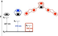
Compared with the HOMO→LUMO excitation (E 0(S2)) of 6.18 eV for 1, those for the [n]paracyclophanes become progressively smaller (i.e., 5.36 (2), 4.98 (3), and 4.42 eV (4)) upon shortening the para bridge from hepta‐ to hexa‐ and pentamethylene, respectively (Table 1). This effect is due to both increased out‐of‐plane distortion and bending of the bridge relative to the aromatic core (Δα=5°, Δβ=8°), as is evident upon comparing [6]paracyclophane (3) with [5]paracyclophane (4). The isomeric [6]‐ and [5]metacyclophanes (5 and 6, respectively), in which the bridge connects two meta carbon centers, show a similar trend with E 0(S1) being 0.40 eV smaller for shorter bridged 6 (4.55 eV) than that for 5 (4.96 eV).45 Moreover, E 0(S1) is systematically blue‐shifted in the case of [n]metacyclophanes compared with their corresponding [n]paracyclophane counterparts. We note that the nature of the participating MOs in the transition differ because the HOMO and HOMO−1 are inverted due to a different mechanism of out‐of‐plane bending than that of paracyclophane (Figure S9 in the Supporting Information).9 Introducing a second benzene ring in a sandwich‐shaped motif held together by para bimethylene bridges, to give [2,2]paracyclophane (7), an E 0(S1) of 4.41 eV is obtained, that is, as expected, red‐shifted by 1.77 eV from 1, but only marginally blue‐shifted (0.03 eV) from that of 4. Apparently, the significant red‐shift of E 0(S1), resulting from intermolecular π–π stacking, is compensated for by the blue‐shift that has its origin in the much smaller bending caused by the eight‐membered bridge of 7 than that of the pentamethylene bridge of 4 (Δα=12°). The strong π–π interaction results from the short transannular distance of 3.10 Å (3.09 Å in the crystal structure),16 which also lengthens the C−C bond of the bimethylene bridges to 1.62 Å. Replacing these bridges for methylene ones, as in [1,1]paracyclophane (8), reduces ΔE H‐L by a significant 41 %, as a result of the shorter inter‐core distance and the larger α and β angles. Our calculated absorption maximum of λ=419 nm for 8 compares well with the reported value of λ=377 nm measured at 77 K in an inert matrix.46 Bending induced by connecting the close‐lying stacked aromatic cores (d=3.0 Å) by a short para hexamethylene bridge reduces ΔE H‐L from 3.6 (co‐facially benzene dimer, see the previous section) to 2.2 eV. Such a large decrease in ΔE H‐L reflects a (non‐linear) cumulative effect of bending and inter‐core distance on ΔE H‐L. However, the counterpart of 8, [1,1]metacyclophane (9) shows a rather large blue‐shift of 1.24 eV from 8. Although bending is similar in both 8 and 9, the loss of π–π stacking in the latter prohibits red‐shift of the absorption relative to that of 8. Adding another methylene bridge to 8 pulls the stacked aromatic cores closer to each other (Δd=0.3 Å) in [1,1,1](1,4,5)cyclophane (10), leading to a marginal red‐shift of about 0.20 eV of E 0(S1) from that of 8. Because the length of the bridge could not be reduced further, we decided to enhance the red‐shift by strengthening π–π stacking by adding one more methylene bridge to 10 to obtain 11 or [1,1,1,1](1,2,4,5)cyclophane. As predicted, compound 11 undergoes a large red‐shift of 0.79 eV from 10. The large red‐shift stems from a stronger π–π stacking due to an extremely short d of 2.4 Å, which is 0.3 Å shorter than that of 10. This indicates that the inter‐core distance decreases with an increase in the number of bridges. Relative to reference 1, compound 11 exhibits an extremely large red‐shift in absorption of about 4.20 eV due to a combined effect of large bending due to multiple short bridges, along with a strong π–π stacking (d=2.40 Å versus 3.79 Å in benzene dimer), giving rise to a highly distorted system. The inherent strain in 11 is reflected in its significantly distorted benzene rings and elongated sp2–sp3 C−C bonds of 1.56 versus 1.50 Å in propene. Although the synthesis of 11 has eluded synthetic chemists due to challenges with stability, its higher homologue, [2.2.2.2](1,2,4,5)cyclophane, has been characterized by Boekelheide and co‐workers.47 Overall, it is evident that shortening the length of the bridge and including multiple bridges enhances the bending and π–π stacking interaction to cumulatively, but non‐linearly, decrease the ΔE H‐L, and consequently, red‐shift E 0(S1).
To enhance the red‐shift of E 0(S1) of the cyclophanes even further, with the aim of achieving NIR absorption,1, 48 we introduced main‐group heteroatoms into the aromatic rings. A heteroatom in a (poly)cyclic aromatic compound can serve as an auxiliary electron donor and/or acceptor and changes energy levels, shapes of the frontier orbitals, and the geometry of the aromatic core.49 For instance, incorporating heavier main‐group elements into benzene rings has been shown to lower ΔE H‐L.8, 9, 50 Upon replacing one of the unsubstituted aromatic carbon atoms of 11 for either a silicon (12) or a phosphorus (13) atom, ΔE H‐L decreases due to both destabilization of the π‐HOMO and stabilization of the π*‐LUMO. This is consistent with studies by Wisor and Czuchajowski,51 who investigated pyridinophanes (Y = N) and found a small red‐shift in the absorption maximum relative to that of the all‐hydrocarbon analogue. The effect of heteroatom substitution is significant because E 0(S1) is red‐shifted by 0.28 and 0.36 eV upon going from 11 to 12 and 13, respectively, and increases to 0.38 eV for the di‐P‐substituted derivative 14. Distortion of the hexagonal structure of 1 due to the larger Si and P atoms (Figure 6 a) reduces the bonding interaction between the carbon pπ lobes of the π‐HOMO adjacent to the heteroatom, which, in turn, leads to a destabilization of the π‐HOMO (Figure 6 b).8 Moreover, Si presents a high‐lying occupied pπ orbital, whereas P presents a low‐lying empty pπ orbital, which mixes with the π framework of the conjugated diene (highlighted in red, see Figure 6 a), both of which result in a decreased ΔE H‐L. Additionally, the out‐of‐plane distortion caused by the enhanced steric repulsion between the larger heteroatom and its neighboring carbon atoms (Δα(11–13)=4°) adds to a decrease in ΔE H‐L.
Figure 6.
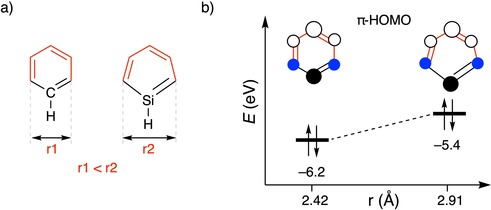
a) Structural distortion (in red) upon heteroatom substitution (Si) in benzene. b) Change in π‐HOMO energy due to distortion of the aromatic core (r) upon introducing Si. The blue filled circles represent the in‐phase pπ lobes of C. The energies were calculated at the BLYP‐D3(BJ)/TZ2P level.
Finally, to even further reduce ΔE H‐L, we applied the push–pull concept52 to di‐P cyclophane 14 in the expectation of a favorable contribution from the charge‐transfer excitation effect. To this end, the para position of one of the phosphabenzene rings of 14 was substituted with an electron‐donating (D) amine group and the other phosphabenzene ring with an electron‐withdrawing (A) cyanide group to give 15. These two substituents cause a red‐shift of E 0(S1) by 0.15 eV, leading to a NIR absorption at 1.45 eV (λ=855 nm, see Table 1). The decrease in ΔE H‐L results from symmetry‐allowed mixing of the high‐lying amine lone pair that destabilizes the π‐HOMO of 14 and the low‐lying cyano π* orbital that stabilizes the overall π*‐LUMO. This decrease in ΔE H‐L upon D/A substitution is in qualitative agreement with previous studies.8, 53 However, in all these modeled systems, the oscillator strength corresponding to the NIR absorption is negligible rendering them to be poor chromophores. Hence, in the next section, we provide a systematic and rational approach to tune the oscillator strength.
Tuning the E0(S1) oscillator strength
The transition probability and oscillator strength (f) of the vertical S1←S0 excitation must both be nonzero for light‐harvesting molecules. This necessitates fine‐tuning of the ground and excited states of our model cyclophanes because all have negligible oscillator strengths (Table 1) due to electric dipole‐forbidden transitions, vanishing transition dipole moments, and/or cancellation of transition dipole moment vectors.54 To circumvent this, we focused on modifying the nature of the MOs involved in the lowest electronic transitions by introducing aromatic substituents.
Although silacyclophane 12 and phosphacyclophane 13 are both asymmetric, their oscillator strengths are vanishingly small for the S1←S0 excitation, but the next lowest excitation, S2←S0, which is essentially a HOMO−1→LUMO transition, exhibits a non‐negligible oscillator strength of about 0.02. Analysis of the all‐carbon homologue 11 provides insight into how to move forward. HOMO of 11 has a nodal plane passing along C1 (or C1′) and C4 (or C4′), leading to zero electronic coupling between the substituents at these positions (see Figure 7 a for atom numbering), but this is not the case for its HOMO−1. Therefore, we aimed to invert the order of HOMO and HOMO−1 by judicious choice of substituents. Such perturbations might enable the oscillator strength to be adjusted and the light‐harvesting properties altered.55 Addition of a single benzene substituent at the C4 position of phosphacyclophane 13 to give 16 (Figure 7) inverts the HOMO and HOMO−1, but f remains negligible for the S1←S0 transition, which is now instead predominantly composed of the HOMO−1 (cf., HOMO of 11)→LUMO transition (Figure 7 b) and, as expected, results in a poor f. This change in the nature of the S1←S0 transition from a HOMO→LUMO transition is due to a large contribution of the coupling matrix, K, in describing this excitation, which becomes clear from Eqs. (3), (4):26a, 56
| (3) |
| (4) |
in which Ω is the four‐index matrix and the excitation energies, ω i, and oscillator strength, f, are obtained by solving the eigenvalue in Eq. (3). Δ represents the orbital energy gap between occupied orbital i and unoccupied orbital a (ϵ a−ϵ i) and K is the coupling matrix, which includes the contribution to the change in density, and thus, other linear response molecular properties if an electron is excited from an occupied to an unoccupied orbital. In a zeroth‐order approximation, in which K is neglected, the lowest excitation is the pure HOMO→LUMO transition. However, the inclusion of K, which is necessary for accurately predicting excitation properties, couple other transitions, such as HOMO−1→LUMO (in our case) with HOMO→LUMO. In 16, a large magnitude of this coupling changes the nature of the lowest excitation and this results again in a negligible f. A similar negligible value of f is obtained for diphenyl‐substituted 17. Interestingly, the second lowest excitation (S2←S0) is close‐lying (0.06 eV) relative to the first (S1←S0), and is composed of the desired HOMO (HOMO−1 of 11)→LUMO transition, which expectedly results in a nonzero f. From our previous analysis, we showed that the large decrease of the ΔE H‐L when α and β=40° completely changed the nature of the S1←S0 transition from being dipole‐forbidden to dipole‐allowed. We hypothesize that we can use this same concept and decrease the ΔE H‐L further, which might lead to a bright lowest singlet excited state. Furthermore, we know that the orbital energy gap is the leading term in linear response TD‐DFT [Eq. (4)]. So, a further decrease in the HOMO–LUMO gap might reduce the dominant effect of the coupling matrix, K, and revert the nature of the S1←S0 transition to a predominant HOMO→LUMO transition, and thereby, increase the magnitude of f. To this end, we introduced π‐conjugated fluorene groups at the C1 and C4 positions to give 18 (Figure 7 c). Fluorene exhibits desirable absorption properties and has found extensive application in co‐polymers to enhance their light‐harvesting character.57 Gratifyingly, this resulted in an intense NIR absorption at λ=785 nm (1.58 eV, see Figure 8 a) composed of the HOMO→LUMO transition, along with a large oscillator strength of 0.22. This result is consistent with the work of Wang et al., who found a red‐shifted emission for fluorene‐dithia[3.3]paracyclophane in both solution and the solid‐state, along with an increase in photoluminescence quantum yield.58 The large f for 18 results mainly from 1) an increase in the transition dipole moment due to an increased spatial overlap between the delocalized HOMO and LUMO on the fluorene moieties (see Figure S11 in the Supporting Information), and 2) a large configuration interaction coefficient, corresponding to the HOMO→LUMO transition (0.94; Figure 8 b). Introduction of the effect of solvation (CH2Cl2) with the continuum solvation model COSMO to stabilize the charge‐separated excited state shifts the longest wavelength peak of 18 even further into the NIR region to λ=821 nm.
Figure 8.
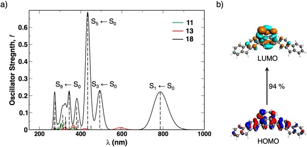
a) Absorption spectra of model dyes 11 (green), 13 (red), and 18 (black) computed at the CAMY‐B3LYP/TZ2P//BLYP‐D3(BJ)/TZ2P level, with an applied gaussian broadening of 0.01 eV (vertical dashed lines represent the excitation energy peaks). b) MO composition of the S1←S0 transition in 18 plotted at isovalue=0.03 au.
Additional benefits of introducing the two large π‐conjugated substituents are more pronounced absorptions with nonzero intensity in the UV/Vis region (see Figure 8 a). The most intense one for 18 is the S5←S0 transition, which represents nearly exclusively a transition from the HOMO to the LUMO+1 (0.93), which corresponds to the LUMO+2 of 11 highlighted in green in Figure 7 b. The strong bathochromic shift (ΔE 0(S1)=0.55 eV) of this excitation compared to that of 11 and its much higher oscillator strength (Δf=0.68) stand out and suggest that the outlined strategy might be of use for the design of light absorbers with a wide spectral response.
Conclusion
The HOMO–LUMO energy gap of model cyclophanes can be reduced and systematically tuned by structural distortion that invokes 1) out‐of‐plane bending of the aromatic core; 2) bending of the bridge with respect to the aromatic core; 3) nature of the bridge substituents; and 4) π–π stacking, of which out‐of‐plane bending, bending of the bridge, and π–π stacking are most prominent. The various parameters are coupled by the length and number of bridges and have a non‐linear cumulative effect on the decrease of the HOMO–LUMO energy gap, and thus, the absorption wavelength. Complex molecules incorporating these design parameters are modeled in a systematic and rational approach to achieve intense NIR absorption.
Cyclophanes with shorter bridges are subject to more bending of the aromatic core and bridge and, when multiple π‐conjugated cores are involved, a tighter π–π stacking. The effect of out‐of‐plane bending could be quantified by dissecting benzene into two allylic fragments. This revealed an antibonding contribution to the π‐HOMO (and thus destabilization) with increasing out‐of‐phase overlap of the allylic π‐HOMOs and stabilization of the π*‐LUMO because the fragment π*‐LUMOs penetrate favorably into each other. Bending the bridge amplifies the decrease of the HOMO–LUMO gap by mixing the orthogonal σ‐ and π‐FMOs of the bridge and aromatic core, respectively. However, the largest change in the MO energies originates from π–π stacking because decreasing the inter‐core distance by reducing the bridge length or increasing the number of bridges enables significant through‐space π–π orbital overlap. Inclusion of a heavy main‐group heteroatom, such as silicon or phosphorus, and adding a push–pull effect to a heavily distorted cyclophane augmented the decrease of the HOMO–LUMO gap and strongly red‐shifted the HOMO→LUMO excitation relative to that of benzene.
These insights, along with a rational approach to tune the oscillator strength, were applied in a proof‐of‐concept design that led to distortion‐controlled cyclophane‐like model dye molecule 18, which had a bright TD‐DFT‐calculated absorption at λ=785 nm and at λ=812 nm if the effect of CH2Cl2 (DCM) as the solvent was included. These absorptions are well into the NIR range and reflect a large redshift of about 600 nm from the HOMO→LUMO excitation of reference benzene. The contribution of the two fluorene groups in 18 is crucial because they cause the needed switching of the highest occupied MOs to convert the dark state into a bright excited state. This finding establishes distortion‐control as an alternative design principle for tuning the optoelectronic structure of organic dye molecules, especially for, but not limited to, red‐shifting absorption into the NIR, with possible applications ranging from bent organic semiconductors59 to molecular switches.60
Conflict of interest
The authors declare no conflict of interest.
Supporting information
As a service to our authors and readers, this journal provides supporting information supplied by the authors. Such materials are peer reviewed and may be re‐organized for online delivery, but are not copy‐edited or typeset. Technical support issues arising from supporting information (other than missing files) should be addressed to the authors.
Supplementary
Acknowledgements
This work is part of the Industrial Partnership Program (IPP) “Computational sciences for energy research” (project 14CSER011), which is part of the Netherlands Organization for Scientific Research (NWO) and co‐financed by Shell Global Solutions International B.V. J.P. thanks the Spanish MINECO (CTQ2016‐77558‐R and MDM‐2017‐0767) and the Catalan Government (2017SGR348). A.K.N. thanks Souloke Sen for insightful discussions on TD‐DFT.
A. K. Narsaria, J. Poater, C. Fonseca Guerra, A. W. Ehlers, T. A. Hamlin, K. Lammertsma, F. M. Bickelhaupt, Chem. Eur. J. 2020, 26, 2080.
Contributor Information
Dr. Trevor A. Hamlin, Email: t.a.hamlin@vu.nl.
Prof. Dr. Koop Lammertsma, Email: k.lammertsma@vu.nl.
Prof. Dr. F. Matthias Bickelhaupt, Email: f.m.bickelhaupt@vu.nl.
References
- 1. Qian G., Wang Z. Y., Chem. Asian J. 2010, 5, 1006. [DOI] [PubMed] [Google Scholar]
- 2.
- 2a. Burke A., Schmidt-Mende L., Ito S., Grätzel M., Chem. Commun. 2007, 234; [DOI] [PubMed] [Google Scholar]
- 2b. Reddy P. Y., Giribabu L., Lyness C., Snaith H. J., Vijaykumar C., Chandrasekharam M., Lakshmikantam M., Yum J.-H., Kalyanasundaram K., Grätzel M., Nazeeruddin M. K., Angew. Chem. Int. Ed. 2007, 46, 373; [DOI] [PubMed] [Google Scholar]; Angew. Chem. 2007, 119, 377. [Google Scholar]
- 3. Hong G., Antaris A. L., Dai H., Nat. Biomed. Eng. 2017, 1, 0010. [Google Scholar]
- 4.
- 4a. Williams E. L., Li J., Jabbour G. E., Appl. Phys. Lett. 2006, 89, 083506; [Google Scholar]
- 4b. Borek C., Hanson K., Djurovich P. I., Thompson M. E., Aznavour K., Bau R., Sun Y., Forrest S. R., Brooks J., Michalski L., Brown J., Angew. Chem. Int. Ed. 2007, 46, 1109; [DOI] [PubMed] [Google Scholar]; Angew. Chem. 2007, 119, 1127. [Google Scholar]
- 5. Albright T. A., Burdett J. K., Whangbo M.-H., Orbital Interactions in Chemistry , 2nd ed., Wiley, Hoboken, 2013. [Google Scholar]
- 6.
- 6a. Katono M., Wielopolski M., Marszalek M., Bessho T., Moser J.-E., Humphry-Baker R., Zakeeruddin S. M., Grätzel M., J. Phys. Chem. C 2014, 118, 16486; [Google Scholar]
- 6b. Chen R., Yang X., Tian H., Wang X., Hagfeldt A., Sun L., Chem. Mater. 2007, 19, 4007; [Google Scholar]
- 6c. Haid S., Marszalek M., Mishra A., Wielopolski M., Teuscher J., Moser J.-E., Humphry-Baker R., Zakeeruddin S. M., Grätzel M., Bäuerle P., Adv. Funct. Mater. 2012, 22, 1291. [Google Scholar]
- 7.
- 7a. Roncali J., Chem. Rev. 1997, 97, 173; [DOI] [PubMed] [Google Scholar]
- 7b. Huckaba A. J., Yella A., McNamara L. E., Steen A. E., Murphy J. S., Carpenter C. A., Puneky G. D., Hammer N. I., Nazeeruddin M. K., Grätzel M., Delcamp J. H., Chem. Eur. J. 2016, 22, 15536. [DOI] [PubMed] [Google Scholar]
- 8. Narsaria A. K., Poater J., Fonseca Guerra C., Ehlers A. W., Lammertsma K., Bickelhaupt F. M., J. Comput. Chem. 2018, 39, 2690. [DOI] [PMC free article] [PubMed] [Google Scholar]
- 9. Narsaria A. K., Hamlin T. A., Lammertsma K., Bickelhaupt F. M., Chem. Eur. J. 2019, 25, 9902. [DOI] [PMC free article] [PubMed] [Google Scholar]
- 10.
- 10a. Darzi E. R., Jasti R., Chem. Soc. Rev. 2015, 44, 6401; [DOI] [PubMed] [Google Scholar]
- 10b. Iwamoto T., Watanabe Y., Sakamoto Y., Suzuki T., Yamago S., J. Am. Chem. Soc. 2011, 133, 8354; [DOI] [PubMed] [Google Scholar]
- 10c. Segawa Y., Fukazawa A., Matsuura S., Omachi H., Yamaguchi S., Irle S., Itami K., Org. Biomol. Chem. 2012, 10, 5979. [DOI] [PubMed] [Google Scholar]
- 11. Cui J., Yao M., Yang H., Liu Z., Ma F., Li Q., Liu R., Zou B., Cui T., Liu Z., Sundqvist B., Liu B., Sci. Rep. 2015, 5, 13398. [DOI] [PMC free article] [PubMed] [Google Scholar]
- 12.
- 12a. Rochefort A., Salahub D. R., Avouris P., Chem. Phys. Lett. 1998, 297, 45; [Google Scholar]
- 12b. Sun L., Li Q., Ren H., Su H., Shi Q. W., Yang J., J. Chem. Phys. 2008, 129, 074704. [DOI] [PubMed] [Google Scholar]
- 13.
- 13a. Chen Z., Giorgi M., Jacquemin D., Elhabiri M., Siri O., Angew. Chem. Int. Ed. 2013, 52, 6250; [DOI] [PubMed] [Google Scholar]; Angew. Chem. 2013, 125, 6370; [Google Scholar]
- 13b. Zucchelli G., Brogioli D., Casazza A. P., Garlaschi F. M., Jennings R. C., Biophys. J. 2007, 93, 2240; [DOI] [PMC free article] [PubMed] [Google Scholar]
- 13c. Haddad R. E., Gazeau S., Pécaut J., Marchon J.-C., Medforth C. J., Shelnutt J. A., J. Am. Chem. Soc. 2003, 125, 1253; [DOI] [PubMed] [Google Scholar]
- 13d. Ryeng H., Ghosh A., J. Am. Chem. Soc. 2002, 124, 8099. [DOI] [PubMed] [Google Scholar]
- 14. Pellegrin M., Recl. Trav. Chim. Pays-Bas 1899, 18, 457. [Google Scholar]
- 15. Brown C. J., Farthing A. C., Nature 1949, 164, 915.15407665 [Google Scholar]
- 16. Cram D. J., Steinberg H., J. Am. Chem. Soc. 1951, 73, 5691. [Google Scholar]
- 17.
- 17a. Gleiter R., Hopf H., Modern Cyclophane Chemistry, Wiley-VCH, Weinheim, 2004; [Google Scholar]
- 17b. Cram D. J., Cram J. M., Acc. Chem. Res. 1971, 4, 204; [Google Scholar]
- 17c. Kraakman P. A., Valk J. M., Niederlander H. A. G., Brouwer D. B. E., Bickelhaupt F. M., De Wolf W. H., Bickelhaupt F., Stam C. H., J. Am. Chem. Soc. 1990, 112, 6638; [Google Scholar]
- 17d. Jenneskens L. W., De Boer H. J. R., De Wolf W. H., Bickelhaupt F., J. Am. Chem. Soc. 1990, 112, 8941; [Google Scholar]
- 17e. Hopf H., Angew. Chem. Int. Ed. 2008, 47, 9808; [DOI] [PubMed] [Google Scholar]; Angew. Chem. 2008, 120, 9954; [Google Scholar]
- 17f. Kleinschroth J., Hopf H., Angew. Chem. Int. Ed. Engl. 1982, 21, 469; [Google Scholar]; Angew. Chem. 1982, 94, 485. [Google Scholar]
- 18.
- 18a. Allinger N. L., Sprague J. T., Liljefors T., J. Am. Chem. Soc. 1974, 96, 5100; [Google Scholar]
- 18b. Cram D. J., Allinger N. L., Steinberg H., J. Am. Chem. Soc. 1954, 76, 6132; [Google Scholar]
- 18c. Ghasemabadi P. G., Yao T., Bodwell G. J., Chem. Soc. Rev. 2015, 44, 6494; [DOI] [PubMed] [Google Scholar]
- 18d. Zhang B., Pascal R. A., Zhao Y., Bodwell G. J., Can. J. Chem. 2017, 95, 460. [Google Scholar]
- 19.
- 19a. te Velde G., Bickelhaupt F. M., Baerends E. J., Fonseca Guerra C., van Gisbergen S. J. A., Snijders J. G., Ziegler T., J. Comput. Chem. 2001, 22, 931; [Google Scholar]
- 19b. Fonseca Guerra C., Snijders J. G., te Velde G., Baerends E. J., Theor. Chem. Acc. 1998, 99, 391; [Google Scholar]
- 19c.ADF2017, SCM, Theoretical Chemistry, Vrije Universiteit, Amsterdam, The Netherlands, http://www.scm.com.
- 20.CYLview, 1.0b; C. Y. Legault, Université de Sherbrooke, 2009 (http://www.cylview.org).
- 21.
- 21a. Becke A. D., Phys. Rev. A 1988, 38, 3098; [DOI] [PubMed] [Google Scholar]
- 21b. Lee C., Yang W., Parr R. G., Phys. Rev. B 1988, 37, 785; [DOI] [PubMed] [Google Scholar]
- 21c. Grimme S., Antony J., Ehrlich S., Krieg H., J. Chem. Phys. 2010, 132, 154104; [DOI] [PubMed] [Google Scholar]
- 21d. Grimme S., Chem. Eur. J. 2004, 10, 3423; [DOI] [PubMed] [Google Scholar]
- 21e. Grimme S., Ehrlich S., Goerigk L., J. Comput. Chem. 2011, 32, 1456. [DOI] [PubMed] [Google Scholar]
- 22. van Lenthe E., Baerends E. J., J. Comput. Chem. 2003, 24, 1142. [DOI] [PubMed] [Google Scholar]
- 23.
- 23a. van Lenthe E., Ehlers A., Baerends E. J., J. Chem. Phys. 1999, 110, 8943; [Google Scholar]
- 23b. van Lenthe E., Baerends E. J., Snijders J. G., J. Chem. Phys. 1993, 99, 4597; [Google Scholar]
- 23c. van Lenthe E., Baerends E. J., Snijders J. G., J. Chem. Phys. 1994, 101, 9783. [Google Scholar]
- 24.
- 24a. Bickelhaupt F. M., Baerends E. J. in Reviews in Computational Chemistry (Eds.: K. B. Lipkowitz, D. B. Boyd), Wiley, Hoboken, 2000, pp. 1–86; [Google Scholar]
- 24b. Ziegler T., Rauk A., Inorg. Chem. 1979, 18, 1755. [Google Scholar]
- 25. Fonseca Guerra C., Handgraaf J. W., Baerends E. J., Bickelhaupt F. M., J. Comput. Chem. 2004, 25, 189. [DOI] [PubMed] [Google Scholar]
- 26.
- 26a. van Gisbergen S. J. A., Snijders J. G., Baerends E. J., Comput. Phys. Commun. 1999, 118, 119; [Google Scholar]
- 26b. Rosa A., Baerends E. J., van Gisbergen S. J. A., van Lenthe E., Groeneveld J. A., Snijders J. G., J. Am. Chem. Soc. 1999, 121, 10356. [Google Scholar]
- 27. González L., Escudero D., Serrano-Andrés L., ChemPhysChem 2011, 13, 28. [DOI] [PubMed] [Google Scholar]
- 28.
- 28a. Grimme S., Parac M., ChemPhysChem 2003, 4, 292; [DOI] [PubMed] [Google Scholar]
- 28b. Richard R. M., Herbert J. M., J. Chem. Theory Comput. 2011, 7, 1296. [DOI] [PubMed] [Google Scholar]
- 29.
- 29a. Grimme S., J. Comput. Chem. 2004, 25, 1463; [DOI] [PubMed] [Google Scholar]
- 29b. Ernzerhof M., Scuseria G. E., J. Chem. Phys. 1999, 110, 5029. [Google Scholar]
- 30.
- 30a. Zhao Y., Truhlar D. G., J. Chem. Phys. 2006, 125, 194101; [DOI] [PubMed] [Google Scholar]
- 30b. Zhao Y., Truhlar D. G., Theor. Chem. Acc. 2008, 120, 215. [Google Scholar]
- 31. Seth M., Ziegler T., J. Chem. Theory Comput. 2012, 8, 901. [DOI] [PubMed] [Google Scholar]
- 32. Jacquemin D., Planchat A., Adamo C., Mennucci B., J. Chem. Theory Comput. 2012, 8, 2359. [DOI] [PubMed] [Google Scholar]
- 33. Demissie T. B., Dodziuk H., Waluk J., Ruud K., Pietrzak M., Vetokhina V., Szymański S., Jaźwiński J., Hopf H., J. Phys. Chem. A 2016, 120, 724. [DOI] [PubMed] [Google Scholar]
- 34.
- 34a. Dev P., Agrawal S., English N. J., J. Chem. Phys. 2012, 136, 224301; [DOI] [PubMed] [Google Scholar]
- 34b. Mewes S. A., Plasser F., Dreuw A., J. Chem. Phys. 2015, 143, 171101. [DOI] [PubMed] [Google Scholar]
- 35. Peach M. J., Benfield P., Helgaker T., Tozer D. J., J. Chem. Phys. 2008, 128, 044118. [DOI] [PubMed] [Google Scholar]
- 36.
- 36a. Pye C. C., Ziegler T., Theor. Chem. Acc. 1999, 101, 396; [Google Scholar]
- 36b. Klamt A., Schüürmann G., J. Chem. Soc. Perkin Trans. 2 1993, 799; [Google Scholar]
- 36c. Klamt A., J. Phys. Chem. 1995, 99, 2224; [Google Scholar]
- 36d. Klamt A., Jonas V., J. Chem. Phys. 1996, 105, 9972. [Google Scholar]
- 37.
- 37a. Sherrill C. D., Acc. Chem. Res. 2013, 46, 1020; [DOI] [PubMed] [Google Scholar]
- 37b. Wang B., Truhlar D. G., J. Chem. Theory Comput. 2010, 6, 3330; [DOI] [PubMed] [Google Scholar]
- 37c. Sutton C., Risko C., Brédas J.-L., Chem. Mater. 2016, 28, 3; [Google Scholar]
- 37d. Gryn′ova G., Corminboeuf C., J. Phys. Chem. Lett. 2016, 7, 5198. [DOI] [PubMed] [Google Scholar]
- 38.
- 38a. Krapp A., Bickelhaupt F. M., Frenking G., Chem. Eur. J. 2006, 12, 9196; [DOI] [PubMed] [Google Scholar]
- 38b. Frenking G., Caramori G. F., Angew. Chem. Int. Ed. 2015, 54, 2596; [DOI] [PubMed] [Google Scholar]; Angew. Chem. 2015, 127, 2632; [Google Scholar]
- 38c. Bickelhaupt F. M., Baerends E. J. in Reviews in Computational Chemistry, Vol. 15 (Eds.: K. B. Lipkowitz, D. B. Boyd), Wiley, Hoboken, 2000, pp. 1–86; [Google Scholar]; Bickelhaupt F. M., Baerends E. J., Rev. Comput. Chem. 2000, 15, 1; [Google Scholar]
- 38d. Spackman M. A., Maslen E. N., J. Phys. Chem. 1986, 90, 2020; [Google Scholar]
- 38e. Hirshfeld F. L., Rzotkiewicz S., Mol. Phys. 1974, 27, 1319; [Google Scholar]
- 38f. Kovács A., Esterhuysen C., Frenking G., Chem. Eur. J. 2005, 11, 1813. [DOI] [PubMed] [Google Scholar]
- 39.
- 39a. Jaffe R. L., Smith G. D., J. Chem. Phys. 1996, 105, 2780; [Google Scholar]
- 39b. Pitoňák M., Neogrády P., R̆ezáč J., Jurečka P., Uran M., Hobza P., J. Chem. Theory Comput. 2008, 4, 1829. [DOI] [PubMed] [Google Scholar]
- 40.
- 40a. Förster T., Angew. Chem. Int. Ed. Engl. 1969, 8, 333; [Google Scholar]; Angew. Chem. 1969, 81, 364; [Google Scholar]
- 40b. Plasser F., Lischka H., J. Chem. Theory Comput. 2012, 8, 2777; [DOI] [PubMed] [Google Scholar]
- 40c. Cardozo T. M., Galliez A. P., Borges I., Plasser F., Aquino A. J. A., Barbatti M., Lischka H., Phys. Chem. Chem. Phys. 2019, 21, 13916. [DOI] [PubMed] [Google Scholar]
- 41.
- 41a. Pignataro S., Mancini V., Ridyard J. N. A., Lempka H. J., J. Chem. Soc. Chem. Commun. 1971, 142; [Google Scholar]
- 41b. Heilbronner E., Yang Z.-Z., Top. Curr. Chem. 1983, 115, 1; [Google Scholar]
- 41c. Canuto S., Zerner M. C., J. Am. Chem. Soc. 1990, 112, 2114; [Google Scholar]
- 41d. Yamakita Y., Yamaguchi M., Ohno K., Chem. Phys. Lett. 2000, 322, 189. [Google Scholar]
- 42.
- 42a. Hestand N. J., Spano F. C., Acc. Chem. Res. 2017, 50, 341; [DOI] [PubMed] [Google Scholar]
- 42b. Kertesz M., Chem. Eur. J. 2019, 25, 400; and references within.29972608 [Google Scholar]
- 43. Brown C. J., J. Chem. Soc. 1953, 3265. [Google Scholar]
- 44. Bacon G. E., Acta Crystallogr. 1951, 4, 558. [Google Scholar]
- 45.[n]Paracyclophane and [n]metacyclophane behave similarly, in that both exhibit a decrease in ΔE H-L due to structural distortion, which leads to a redshift in E 0(S1), relative to benzene (1). However, there exists a stark contrast between the two cyclophanes in terms of their reactivity. For example, different modes of structural distortion induced by either a meta or para bridge result in distinct physical mechanisms that control their Diels–Alder reactivity, as we have previously outlined in ref. [9].
- 46. Tsuji T., Ohkita M., Konno T., Nishida S., J. Am. Chem. Soc. 1997, 119, 8425. [Google Scholar]
- 47. Gray R., Boekelheide V., J. Am. Chem. Soc. 1979, 101, 2128. [Google Scholar]
- 48. Fabian J., Nakazumi H., Matsuoka M., Chem. Rev. 1992, 92, 1197. [Google Scholar]
- 49.
- 49a. Parke S. M., Boone M. P., Rivard E., Chem. Commun. 2016, 52, 9485; [DOI] [PubMed] [Google Scholar]
- 49b. Higashino T., Ishida K., Satoh T., Matano Y., Imahori H., J. Org. Chem. 2018, 83, 3397; [DOI] [PubMed] [Google Scholar]
- 49c. Ashe A. J., J. Am. Chem. Soc. 1971, 93, 3293; [Google Scholar]
- 49d. Ishibashi J. S. A., Dargelos A., Darrigan C., Chrostowska A., Liu S.-Y., Organometallics 2017, 36, 2494; [Google Scholar]
- 49e. Liu Z., Ishibashi J. S. A., Darrigan C., Dargelos A., Chrostowska A., Li B., Vasiliu M., Dixon D. A., Liu S.-Y., J. Am. Chem. Soc. 2017, 139, 6082; [DOI] [PubMed] [Google Scholar]
- 49f. Böhnke J., Braunschweig H., Jiménez-Halla J. O. C., Krummenacher I., Stennett T. E., J. Am. Chem. Soc. 2018, 140, 848. [DOI] [PubMed] [Google Scholar]
- 50.
- 50a. Burrow P. D., Ashe A. J., Bellville D. J., Jordan K. D., J. Am. Chem. Soc. 1982, 104, 425; [Google Scholar]
- 50b. Nakata N., Takeda N., Tokitoh N., J. Am. Chem. Soc. 2002, 124, 6914; [DOI] [PubMed] [Google Scholar]
- 50c. Ishii T., Suzuki K., Nakamura T., Yamashita M., J. Am. Chem. Soc. 2016, 138, 12787; [DOI] [PubMed] [Google Scholar]
- 50d. Tokitoh N., Wakita K., Okazaki R., Nagase S., von Ragué Schleyer P., Jiao H., J. Am. Chem. Soc. 1997, 119, 6951; [Google Scholar]
- 50e. Draper S. M., Gregg D. J., Madathil R., J. Am. Chem. Soc. 2002, 124, 3486; [DOI] [PubMed] [Google Scholar]
- 50f. Wang X., Zhang F., Schellhammer K. S., Machata P., Ortmann F., Cuniberti G., Fu Y., Hunger J., Tang R., Popov A. A., Berger R., Müllen K., Feng X., J. Am. Chem. Soc. 2016, 138, 11606. [DOI] [PubMed] [Google Scholar]
- 51. Wisor A. K., Czuchajowski L., J. Phys. Chem. 1986, 90, 1541. [Google Scholar]
- 52.
- 52a. Eakins G. L., Alford J. S., Tiegs B. J., Breyfogle B. E., Stearman C. J., J. Phys. Org. Chem. 2011, 24, 1119; [Google Scholar]
- 52b. Bureš F., RSC Adv. 2014, 4, 58826; [Google Scholar]
- 52c. Duan C., Huang F., Cao Y., J. Mater. Chem. 2012, 22, 10416. [Google Scholar]
- 53.
- 53a. Mulder J. R., Fonseca Guerra C., Slootweg J. C., Lammertsma K., Bickelhaupt F. M., J. Comput. Chem. 2016, 37, 304; [DOI] [PubMed] [Google Scholar]
- 53b. Ottonelli M., Piccardo M., Duce D., Thea S., Dellepiane G., J. Phys. Chem. A 2012, 116, 611; [DOI] [PubMed] [Google Scholar]
- 53c. Ji L., Lorbach A., Edkins R. M., Marder T. B., J. Org. Chem. 2015, 80, 5658. [DOI] [PubMed] [Google Scholar]
- 54. Guidez E. B., Aikens C. M., J. Phys. Chem. C 2013, 117, 21466. [Google Scholar]
- 55.
- 55a. Crawford A. G., Dwyer A. D., Liu Z., Steffen A., Beeby A., Pålsson L.-O., Tozer D. J., Marder T. B., J. Am. Chem. Soc. 2011, 133, 13349; [DOI] [PubMed] [Google Scholar]
- 55b. Ji L., Edkins R. M., Lorbach A., Krummenacher I., Brückner C., Eichhorn A., Braunschweig H., Engels B., Low P. J., Marder T. B., J. Am. Chem. Soc. 2015, 137, 6750; [DOI] [PubMed] [Google Scholar]
- 55c. Merz J., Fink J., Friedrich A., Krummenacher I., Mamari H. H. A., Lorenzen S., Haehnel M., Eichhorn A., Moos M., Holzapfel M., Braunschweig H., Lambert C., Steffen A., Ji L., Marder T. B., Chem. Eur. J. 2017, 23, 13164. [DOI] [PubMed] [Google Scholar]
- 56. Marques M. A. L., Maitra N. T., Nogueira F. M. S., Gross E. K. U., Rubio A., Fundamentals of Time-Dependent Density Functional Theory, Springer, Heidelberg, 1996. [Google Scholar]
- 57.
- 57a. Najechalski P., Morel Y., Stéphan O., Baldeck P. L., Chem. Phys. Lett. 2001, 343, 44; [Google Scholar]
- 57b. Watters D. C., Hunan Y., Pearson A. J., James K., Ahmed I., David L., Macromol. Rapid Commun. 2013, 34, 1157; [DOI] [PubMed] [Google Scholar]
- 57c. Huang F., Chen K.-S., Yip H.-L., Hau S. K., Acton O., Zhang Y., Luo J., Jen A. K. Y., J. Am. Chem. Soc. 2009, 131, 13886. [DOI] [PubMed] [Google Scholar]
- 58.
- 58a. Wang W.-L., Xu J., Sun Z., Zhang X., Lu Y., Lai Y.-H., Macromolecules 2006, 39, 7277; [Google Scholar]
- 58b. Wang W., Xu J., Lai Y.-H., Org. Lett. 2003, 5, 2765. [DOI] [PubMed] [Google Scholar]
- 59.
- 59a. Ball M., Zhang B., Zhong Y., Fowler B., Xiao S., Ng F., Steigerwald M., Nuckolls C., Acc. Chem. Res. 2019, 52, 1068; [DOI] [PubMed] [Google Scholar]
- 59b. Zhang B., Trinh M. T., Fowler B., Ball M., Xu Q., Ng F., Steigerwald M. L., Zhu X. Y., Nuckolls C., Zhong Y., J. Am. Chem. Soc. 2016, 138, 16426. [DOI] [PubMed] [Google Scholar]
- 60. Bléger D., Hecht S., Angew. Chem. Int. Ed. 2015, 54, 11338; [DOI] [PubMed] [Google Scholar]; Angew. Chem. 2015, 127, 11494. [Google Scholar]
Associated Data
This section collects any data citations, data availability statements, or supplementary materials included in this article.
Supplementary Materials
As a service to our authors and readers, this journal provides supporting information supplied by the authors. Such materials are peer reviewed and may be re‐organized for online delivery, but are not copy‐edited or typeset. Technical support issues arising from supporting information (other than missing files) should be addressed to the authors.
Supplementary