Abstract
The reduced micromorphic model (RMM) is used to study the effect of the applied force on a hemisphere made of phononic crystals that belongs to the metamaterials group. The strain tensor, the micro-strain tensor and the coupling between them are the kinematic relations used to measure the deformation and micro-deformation of the representative volume element of these materials. The free energy function, the constitutive relations, the field equations, and the boundary conditions are presented firstly in the Cartesian coordinate. Then, the orthogonal curvilinear coordinates are introduced as a general coordinate to describe the physical quantities included in the RMM. The spherical coordinates are deduced as a special case from the curvilinear coordinates to study the deformation and micro-deformation for the hemisphere. The kinematic relations and the governing equations of the model are considered to changing with the radius of the hemisphere only. The analytical solutions of the field equations are also obtained by using the Frobenius series satisfying the given boundary conditions and consequently the value of the physical constants of the problem is determined. Numerical applications for the obtained results are introduced with discussion. The results showed that the displacement has a greater effect rather than the micro-strain, when it is measured relative to the classical physical quantities while the micro-strain has a greater effect rather than the displacement, when it is measured relative to the nanoscale physical quantities.
Subject terms: Nanoscale materials, Structural materials, Mechanical engineering, Nanoscale materials
Introduction
Metamaterials are fabricated engineering materials with periodic internal structures. These materials have special properties that do not exist in other natural materials. They can be designed to prohibit the propagation of elastic waves in the bandgap frequency range effectively. This property has many potential applications in the vibration and noise reduction areas. Besides this property, there are many applications for metamaterials in the fields of technology, industrial engineering, telecommunication equipment, optical filters, medical devices and mobile communication systems and others.
The main idea of constructing metamaterials is attributed to Sir J.C. Bose in 1898. He suggested the idea of the existence of artificial materials by carrying the microwave experiment on twisted structures1,2. Winston E. Kock3,4, used the optical radio waves properties to develop new type of antennas made of metamaterial. V. G. Veselago5, introduced a theoretical model that predicts the propagation of electromagnetic waves in left-handed materials. During the last few decades, more attention was given to metamaterials. This is because of their important applications in recent industries. Theoretical formulation and mechanical applications can be found in refs. 6–9.
The idea of building metamaterials was extended to include elastic and acoustic waves by Ding et al.10, where the authors proposed metamaterials with simultaneously negative bulk modulus and mass density. Wu et al.11 proposed a new type of elastic metamaterials made from fluid-solid components possessing negative shear modulus and negative mass density for a large frequency domain. To study the new phenomena at the micro-scale, many theories have been introduced to modify the classical theory of continuum mechanics by adding an additional degree of freedom. This describes the micro-effects relative to the macro-effects. Micropolar theory (Cosserat theory)12, couple stress theory13, micromorphic theory14, microstructure theory15, and micropolar theory16 are extensions of the classical field theory to microscopic field theory in space and time scales. Among these theories, the micromorphic theory developed by Eringen and Suhubi17,18 and Eringen19,20 is an extension of the classical field theories to microscopic time and space scales. In this new theory, the concept of material point used in classical field theory is replaced by a representative volume element (RVE) that can move, deform, rotate and stretch. Also, the molecules that constitute the RVE can deform and rotate. Moreover, the Micromorphic model can be reduced to yield other models. This can be achieved by imposing internal constraints prescribed on the micro-deformation21. When the micro-deformation is constrained to be pure rotation, micropolar theory is obtained. Also, when the micro-deformation coincides with the deformation gradient, the second gradient theory is obtained. Classical field theory is retrieved when the displacement field is a linear transformation and the micro-deformation vanishes.
Among the important phenomena that characterize the micromorphic model: the size-dependent effect, 18 length scale parameters for the isotropic case, two types of wave propagation, acoustic and optic waves, and bandgaps in the frequency domain.
Micromorphic theory provides basic field equations and constitutive relations for large classes of materials such as artificial materials, porous materials, composites, polymers, crystals, etc., whose REV possesses independent degrees of freedom and described boundary conditions for each boundary-value problem. Neff et al.22, proposed a relaxed linear elastic micromorphic model to reduce the number of material parameters. The number of the materials parameters is reduced to 9, the coupling between materials parameters is reduced to 4 dependent +3 independent. Also, the types of waves are acoustic waves, optic waves, and standing waves for the relaxed micromorphic model. Shaat23 reduced the number of the material parameters to 8, the coupling between materials parameters are 8 dependent + 0 independent. Three types of waves are obtained. Shaat and El Dhaba, in24 used the so-called reduced micromorphic model (RMM) to study the equivalent shear modulus for composite metamaterials.
The main objective of this article is to use the generalized curvilinear coordinates to introduce a novel description for the reduced micromorphic model with extension to spherical coordinates and applications in engineering and mechanics. The importance of this study arises from its potential applications in spongy materials, granular materials, as well as for materials used in lubrication and fluidization for the mechanical parts in cars, trucks and internal structure of engines. The paper is organized as follows: Section 2 is devoted to introducing the RMM in Cartesian coordinates with complete description of the kinematic relations, the definition of the strain energy function as well as the description of the constitutive relations, the field equations and the boundary conditions. Section 3 describes the mathematical formulas of the model in general curvilinear coordinates. An application for the model in spherical polar coordinates is presented in Section 4. Finally, in Section 5 we find the solution of the considered problem. The obtained results are presented in Section 6 with detailed discussion. Finally, the main findings of this study are presented in Section 7.
The RMM in Cartesian Coordinates
Because the classical theories of continuum mechanics do not have the ability to represent the nanoscale phenomena, the reduced micromorphic model (RMM)23 is introduced to study such phenomena at the micro-scale level. The RMM introduces the micro-strain tensor as an unknown measure, besides the displacement components. Also, it introduces the coupling between the strain tensor and the micro-strain tensor as a coupling measure with elimination of the repeated effects. In addition to its ability to reduce the material parameters, the RMM generates more field equations and reduces the order of the partial differential equations of the model. These properties make it possible to obtain analytical solutions for the physical state variables of the model. Materials whose behavior is described by this model are called “multiscale materials” or micromorphic materials.
In RMM, the kinematical variables are defined as follows:
| 1 |
where denote the classical strain tensor, is the micro-strain tensor, is the coupling between the micro-strain and the macro-strain and is the gradient of the micro-strain tensor .
The equations of motion can be derived by using variational methods and are given as:
| 2 |
the natural boundary conditions are
where is the mass density of the macro-scale material, is the mass density of the material particle, and J denotes a microinertia density per unit mass, and are the body force and the body higher-order-moments respectively.
The constitutive relations are related to the free energy function by:
| 3 |
where is the free energy function in terms of internal variables, is the micro-stress tensor, can be defined as the residual stress and is a higher order micro-stress tensor.
According to23,24, the free energy is taken in the form
| 4 |
where and μm are the elastic moduli of the microstructure, λ and μ are the elastic moduli of the confined material between two particles, λc and μc are two elastic moduli accounting for the coupling between the micro-strain and the macro-strain, and are length scale parameters. Such a medium is composed of deformed molecules and have twelve degree of freedom: three translational, three rotational and six micro-deformations25 and26. Many authors introduce a simplified version of the mathematical model for such materials in order to reduce the material parameters22 and23.
Substitute Eq. (4) into Eq. (3) to get the constitutive relations as:
| 5 |
The RMM Model in Orthogonal Curvilinear Coordinates
In this section, we introduce a theoretical method to obtain the governing equations, boundary conditions and the constitutive relations for the RMM in orthogonal curvilinear coordinates. The main idea of the method depends on two concepts mentioned by Eringen27. We introduce the main rules for the derivatives of the covariant and contravariant vectors, and the second and higher orders contravariant and mixed tensors as follows:
| 6 |
where Ai are the vector contravariant components, Bjk- the second rank tensor contravariant components, - the components of second rank mixed tensor, Dijk- the contravariant components of third rank tensor and , are the components of the third rank mixed tensors. are the known Christoffel symbols of the second kind satisfying and defined in orthogonal curvilinear coordinates as follows28:
| 7 |
where gij are the metric tensor components.
Following the two concepts proposed by Eringen27, we replace the partial differentiation (,) with the covariant differentiation (;) taking in consideration the repeated indices summation rule.
Therefore, the kinematic relations (1) can be written in mixed tensor form as follows:
| 8 |
Following29,30, we can use the following relation in the second term:
Using Eq. (6), Eq. (8) can be written as:
| 9 |
The constitutive relations in terms of the contravariant components are given by:
| 10 |
Following27–30, the equations of motion in the RMM model may be written in the form:
| 11 |
where (;) denotes covariant differentiation.
Using Eq. (6), the covariant derivatives of the second and third rank tensors are:
| 12 |
Neglecting external forces and moments, substituting Eq. (12) into Eq. (11) one gets:
| 13 |
According to30 and31, the vector and tensor physical components are
| 14 |
where are the Lamé coefficients. Also, the relation between the contravariant and covariant components are:
To obtain the kinematic relations, the constitutive relations and the field equations in terms of the physical quantities we substitute Eq. (14) into Eqs. (9), (10) and (13):
| 15 |
| 16 |
and
| 17 |
It should be noted that some authors write the physical components as mixed tensors, as in29,30, while others write the physical components as covariant tensors as in32.
Half-space Involving Spherical Symmetry
Assume the an isotropic material occupying the half-space , in the xyz-plane containing a metamaterial hemisphere with radius R. Using the spherical coordinates (r, θ, ) (Fig. 1),
Figure 1.
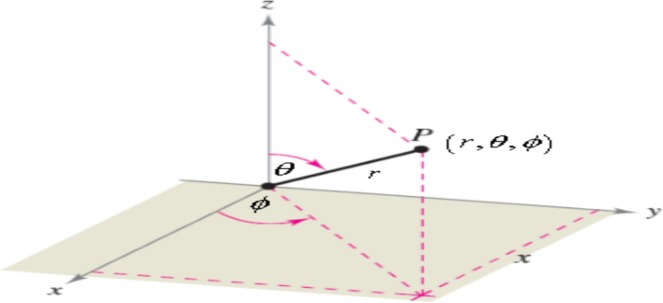
Spherical coordinates system.
where,
| 18 |
the metric tensor in spherical coordinates is defined as:
and the components of the metric tensor are:
| 19 |
the Christoffel symbol of the second kind are:
| 20 |
without any body forces and body higher-order-moments and under the assumption of central symmetry, it is expected that the components of the displacement and micro-strain fields along and vanish, hence
| 21 |
Substitute the Eqs. (19–21) into Eq. (15), to get the kinematic relations in spherical coordinates as follows
| 22 |
Similarly, substitute Eqs. (19–21) into Eq. (16) to get components of the micro-stress tensor in spherical coordinates:
| 23 |
the components of the residual stress tensor in spherical coordinates:
| 24 |
and the components of the higher order micro-stress tensor with , in spherical coordinates:
| 25 |
with
Substituting Eqs. (19–20) into Eq. (13) and neglecting the dynamic effects, we get the field equations in static equilibrium as follows:
| 26 |
Substitute Eqs. (23–25) into Eq. (26) to obtain the field equations of a hemisphere made of elastic phononic material in spherical coordinate as follows:
| 27 |
subjected to the boundary conditions
| 28 |
Figure 2. represents a hemisphere with radius R made of an elastic phononic material, the Cartesian coordinates are chosen at the lower surface of the hemisphere, we take the hemisphere fixed at origin of the coordinates and subjected to an external force in r-direction.
Figure 2.
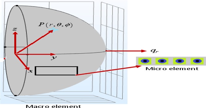
Hemisphere embedded in an isotropic half-space.
The hemisphere is described by
| 29 |
The Analytical Solution
Frobenius series is employed to get the analytical solution for the system of ordinary differential equations in (27) with the boundary conditions in Eq. (28). Since the point (0, 0, 0) is a regular point, one can express the functions ur and srr in terms of the variable r as follows:
| 30 |
where An and Bn are constants to be determined from the given boundary conditions.
Substituting the expressions for the two functions ur and srr and their derivatives into Eq. (27), we obtain
| 31 |
Equation (31) is satisfied if we choose
| 32 |
and we can prove the following relations between the constants:
with
Based on the previous mathematical calculations, Eq. (30) takes the form
| 33 |
| 34 |
A solution to the system of ordinary differential Eq. (27) may be found in series form as in (30). Applying the boundary conditions (28), we find that the first boundary condition is automatically satisfied while the second one gives
with
Numerical Results
Table 1 shows the values for the physical parameters23 for an epoxy matrix and the inclusions materials.
Table 1.
Phononic material constants.
| Radius of the sphere | |
| Micro-inertia density | |
| Micro-moduli | |
| Macro-moduli | |
| Mass density | |
| Coupling moduli | |
| Length scales | |
| the rule of mixture | |
| The applied force |
The following figures are obtained depending on the numerical values for materials parameters listed in Tables (1) and (2).
Table 2.
Radius of the inclusions d, number of inclusions and the frequency.
| d | M = R/2d | f = 2 Md3/R3 |
|---|---|---|
| 0.01 | 1000 | |
| 0.0125 | 800 | |
| 0.016 | 625 | |
| 0.02 | 500 | |
| 0.025 | 400 | |
| 0.04 | 250 | |
| 0.05, | 200 | |
| 0.08 | 125 | |
| 0.1 | 100 | |
| 0.2 | 50 |
Figures (3 and 4) show the displacement and the micro-strain at the hemisphere surface. It is noted that the displacement and the micro-strain increase at the surface. Also, the micro-strain relative to the radius is of order 10−4 and the displacement relative to the radius is of order 10−3. Figures (5 and 6) show the displacement and the micro-strain for different values for the ratio with changing . We note that the displacement increases in a linear way until then decreases until , then becomes constant. On the other hand, the micro-strain decreases in a nonlinear way with increasing .
Figure 3.
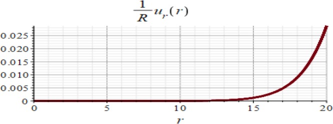
Displacement in r-direction when R = 20 cm.
Figure 4.
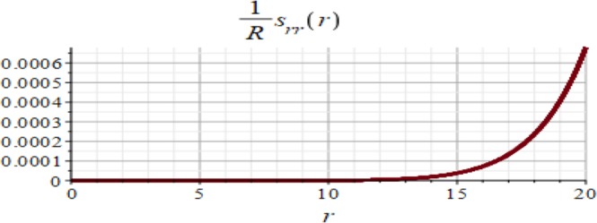
Micro-strain in r-direction when R = 20 cm.
Figure 5.
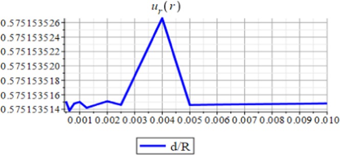
Displacement in r-direction with changing
Figure 6.
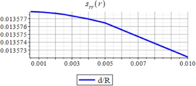
Micro-strain in r-direction with changing .
Figures (7 and 8) show the displacement and micro-strain with changing with the frequency respectively. The change in the displacement can be tangible at the nanoscale (10−9), while the change in the micro-strain is linear decreasing and can be tangible at the microscale (10−6).
Figure 7.
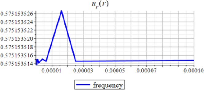
Displacement in r-direction for different values of the frequency.
Figure 8.
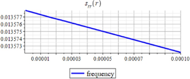
Micro-strain in r-direction for different values of the frequency.
Figures (9 and 10) show the displacement and micro-strain with changing with the ration μc/μ respectively. The change in the displacement can be tangible at the nanoscale (10−9) while the change in the micro-strain is linear increasing and can be tangible at the microscale (10−6). Figure (11) show the initial and current position of the hemisphere due to the micro-strain and displacement at the surface, the total deformation of the hemisphere is linear. Note that we measure only the deformation of objects on their surfaces. Figure (12) shows the distribution of the displacement and the micro-strain at the surface of the hemisphere, they are uniformly distributed.
Figure 9.
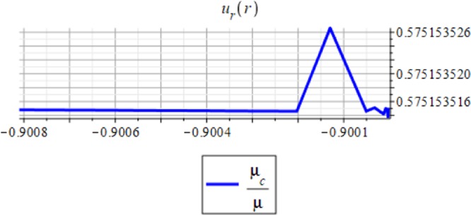
Displacement in r-direction for different values of μc/μ.
Figure 10.
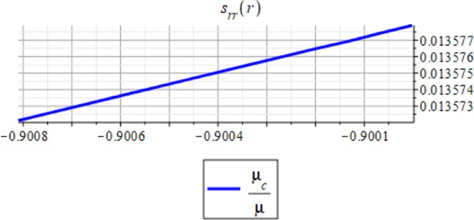
Micro-strain in r-direction for different values of μc/μ.
Figure 11.
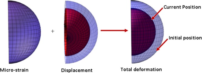
Initial and current positions for the hemisphere.
Figure 12.

Displacement and micro-strain distribution at surface of the hemisphere.
Concluding Remarks
In this paper, the reduced micromorphic model (RMM) is reformulated and presented in orthogonal curvilinear coordinates. Specific forms for the field equations, boundary conditions, and the constitutive relations have been derived in spherical coordinates. This model may be conveniently applied to a wide range of problems. As an application for this model, a hemisphere made of phononic crystals is considered, where the main unknown functions are the displacement and the micro-strain, changing with the radius of the hemisphere only, and neglecting any dependence on the other coordinates.
The analytical solution is obtained for the field equations using Frobenius series. The unknown coefficients of the considered problem are determined. The results of this study are summarized as follows:
The displacement and the micro-strain are concentrated at the surface of the hemisphere.
The displacement increases linearly with the increase of the inclusion radius.
The micro-strain linearly decreases when , and decreases linearly when In other words, when the number of inclusions is 100 or 50, the change in micro-strain is linearly decreasing.
The displacement has a greater effect than the micro-strain, when it is measured relative to the classical physical quantities as on Figs. (3 and 4).
The micro-strain has a greater effect than the displacement when it is measured relative to the nanoscale physical quantities as on Figs. (5–10).
Acknowledgements
I would like to express my deep thanks and appreciation to Professors Ahmed F. Ghaleb and M. E. Gabr for their revision of the text and for various suggestions.
Author contributions
A. R. El Dhaba prepared this paper.
Competing interests
The author declares no competing interests.
Footnotes
Publisher’s note Springer Nature remains neutral with regard to jurisdictional claims in published maps and institutional affiliations.
References
- 1.Bose JC. On the Rotation of Plane of Polarization of Electric Waves by a Twisted Structure. Proc. Roy. Soc. 1898;63:46–152. [Google Scholar]
- 2.Bose, J. C. Collected Physical Papers, New York: Longmans, Green & Co (1927).
- 3.Kock WE. Metal-Lens Antennas. Proc. IRE. 1946;34(11):828–836. doi: 10.1109/JRPROC.1946.232264. [DOI] [Google Scholar]
- 4.Kock WE. Metallic delay lenses. Bell Syst. Tech. J. 1948;27:58–82. doi: 10.1002/j.1538-7305.1948.tb01331.x. [DOI] [Google Scholar]
- 5.Veselago V. The Electrodynamics of substances with simultaneously negative values of ε and μ, Soviet Phys. USPEKHI. 1968;10(4):509–514. doi: 10.1070/PU1968v010n04ABEH003699. [DOI] [Google Scholar]
- 6.Pendry JB. Negative Refraction makes a Perfect Lens. Phys. Rev. Lett. 2000;85(18):3966–3969. doi: 10.1103/PhysRevLett.85.3966. [DOI] [PubMed] [Google Scholar]
- 7.Smith DR, Padilla WJ, Vier DC, Nemat-Nasser SC, Schultz S. Composite Medium with Simultaneously Negative Permeability and Permittivity. Phys. Rev. Lett. 2000;84(18):4184–4187. doi: 10.1103/PhysRevLett.84.4184. [DOI] [PubMed] [Google Scholar]
- 8.Smith DR, Kroll N. Negative Refractive Index in Left-Handed Materials. Phys. Rev. Lett. 2000;85(14):2933–2936. doi: 10.1103/PhysRevLett.85.2933. [DOI] [PubMed] [Google Scholar]
- 9.Alu A, Engheta N. Radiation from a Travelling-Wave Current Sheet at the Interface between a Conventional Material and a Metamaterial with Negative Permittivity and Permeability. Microwave Opt. Techn. Lett. 2002;35(6):460–463. doi: 10.1002/mop.10638. [DOI] [Google Scholar]
- 10.Ding Y, Liu Z, Qiu C, Shi J. Metamaterial with Simultaneously Negative Bulk Modulus and Mass Density. Phys. Rev. Lett. 2007;99:093904. doi: 10.1103/PhysRevLett.99.093904. [DOI] [PubMed] [Google Scholar]
- 11.Wu Y, Lai Y, Zhang Z-Q. Elastic metamaterials with simultaneously negative effective shear modulus and mass density. Phys. Rev. Lett. 2011;107(10):105506. doi: 10.1103/PhysRevLett.107.105506. [DOI] [PubMed] [Google Scholar]
- 12.Cosserat, E & Cosserat, F. Theories des Corps Deformable, Hermann, Paris (1909).
- 13.Toupin RA. Elastic materials with couple-stresses. Arch. Rat. Mech. Anal. 1962;11:385–414. doi: 10.1007/BF00253945. [DOI] [Google Scholar]
- 14.Eringen AC. Simple micro-fluids. Int. J. Engng. Sci. 1964;2:205–217. doi: 10.1016/0020-7225(64)90005-9. [DOI] [Google Scholar]
- 15.Mindlin RD. Microstructure in linear elasticity. Arch. Rat. Mech. Anal. 1964;16:51–78. doi: 10.1007/BF00248490. [DOI] [Google Scholar]
- 16.Eringen, A. C. Theory of micropolar continua, In Proc. Ninth Midwestern Mechanics Conference, Wisconsin, 16-18 August, Wiley, New York (1965).
- 17.Eringen AC, Suhubi ES. Nonlinear theory of simple micro-elastic solids I. Int. J. Engng. Sci. 1964;2:189–203. doi: 10.1016/0020-7225(64)90004-7. [DOI] [Google Scholar]
- 18.Eringen AC, Suhubi ES. Nonlinear theory of simple micro-elastic solids II, Int. J. Engng. Sci. 1964;2:389–404. doi: 10.1016/0020-7225(64)90017-5. [DOI] [Google Scholar]
- 19.Eringen, A. C. Microcontinuum Field Theories-I: Foundations and Solids, Springer, New York (1999).
- 20.Eringen, A. C. Microcontinuum Field Theories-II: Fluent Media, Springer, New York (2001).
- 21.Forest, S. Micromorphic Media. In: Altenbach H., Eremeyev V. A. (Eds.) Generalized Continua from the Theory to Engineering Applications. CISM International Centre for Mechanical Sciences (Courses and Lectures), vol 541. Springer, Vienna (2013).
- 22.Neff P, Ghiba ID, Madeo A, Placidi L, Rosi G. A unifying perspective: The relaxed linear micromorphic continuum. Cont. Mech. Thermodyn. 2014;26:639–681. doi: 10.1007/s00161-013-0322-9. [DOI] [Google Scholar]
- 23.Shaat M. A reduced micromorphic model for multiscale materials and its applications in wave propagation. Composite Struct. 2018;201:446–454. doi: 10.1016/j.compstruct.2018.06.057. [DOI] [Google Scholar]
- 24.Shaat M, El Dhaba AR. On the equivalent shear modulus of composite metamaterials. Composites Part B: Engineering. 2019;172(1):506–515. doi: 10.1016/j.compositesb.2019.05.056. [DOI] [Google Scholar]
- 25.Eringen AC. Balance laws of micromorphic mechanics. Int. J. Engng. Sci. 1970;8(10):819–828. doi: 10.1016/0020-7225(70)90084-4. [DOI] [Google Scholar]
- 26.Eringen AC. Balance laws of micromorphic continua revisited. Int. J. Engng Sci. 1992;30(6):805–810. doi: 10.1016/0020-7225(92)90109-T. [DOI] [Google Scholar]
- 27.Eringen, A. C. Mechanics of Continua. John Wiley & Sons, Inc., New York (1967).
- 28.Ashoori A, Mahmoodi MJ. The modified version of strain gradient and couple stress theories in general curvilinear coordinates. Eur. J. Mech. A/Solids. 2015;49:441–454. doi: 10.1016/j.euromechsol.2014.09.002. [DOI] [Google Scholar]
- 29.Zhao J, Pedroso D. Strain gradient theory in orthogonal curvilinear coordinates. Int. J. Solids Struct. 2008;45:3507–3520. doi: 10.1016/j.ijsolstr.2008.02.011. [DOI] [Google Scholar]
- 30.Ojaghnezhad F, Shodja HM. Second strain gradient theory in orthogonal curvilinear coordinates: prediction of the relaxation of a solid nanosphere and embedded spherical nanocavity. Appl. Math. Mod. 2019;76:669–698. doi: 10.1016/j.apm.2019.06.021. [DOI] [Google Scholar]
- 31.Liu D, He Y, Zhang B, Shen L. Formulation of Toupin-Mindlin strain gradient theory in prolate and oblate spheroidal coordinates. Eur. J. Mech. A/Solids. 2015;49:227–241. doi: 10.1016/j.euromechsol.2014.07.015. [DOI] [Google Scholar]
- 32.Farokhi H, Ghayesh MH. Modified couple stress theory in orthogonal curvilinear coordinates. Acta Mech. 2019;230(3):851–869. doi: 10.1007/s00707-018-2331-z. [DOI] [Google Scholar]


