Abstract
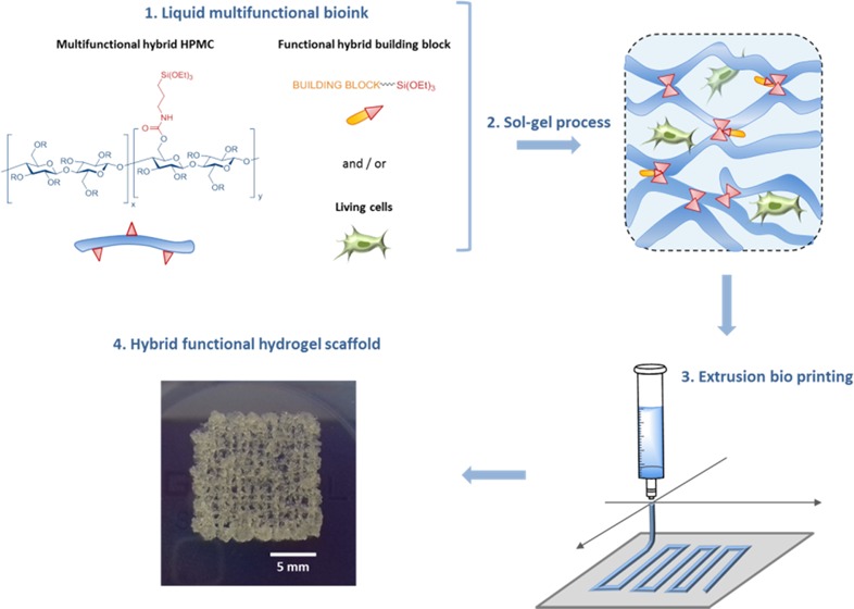
An inorganic sol–gel polymerization process was used as a cross-linking reaction during three-dimensional (3D) bioprinting of cell-containing hydrogel scaffolds. Hybrid hydroxypropyl methyl cellulose (HPMC), with a controlled ratio of silylation, was prepared and isolated as a 3D-network precursor. When dissolved in a biological buffer containing human mesenchymal stem cells, it yields a bioink that can be printed during polymerization by extrusion. It is worth noting that the sol–gel process proceeded at pH 7.4 using biocompatible mode of catalysis (NaF and glycine). The printing window was determined by rheology and viscosity measurements. The physicochemical properties of hydrogels were studied. Covalent functionalization of the network can be easily performed by adding a triethoxysilyl-containing molecule; a fluorescent hybrid molecule was used as a proof of concept.
Introduction
Thanks to the affordability of three-dimensional (3D) printers, the simplicity of the process, and its compatibility with a large number of biopolymers, extrusion-based printing has emerged as a method of choice for rapid fabrication of hydrogel constructs.1 As a direct ink writing (DIW) technology, a continuous filament of material is extruded out of a nozzle on a print head moved in the x/y/z direction to construct the desired shape, layer-by-layer. This automated technology is the most common for the reproducible 3D printing of materials in the biofabrication field. When printed with a biocompatible and cell-adherent material, the surface of any scaffold can be easily seeded with cells. However, the embedment of cells within the material is required for most advanced tissue engineering applications.2−4 Indeed, the culture of cells in three dimensions is required to mimic a natural tissue and only hydrogels can be used as such extracellular matrix (ECM) surrogates.5−7 Printer cartridges have to be filled with a cell-containing buffer, hydrogel precursors, and any other additional components to impart the desired physiochemical, mechanical, and biological properties to the resulting 3D-printed scaffold.8 This cell-containing printable mixture is named a bioink. Physical hydrogels obtained from natural biopolymers (i.e., alginate9−13 and collagen14−17) dominate the field. However, when long-lasting scaffolds have to be printed for more demanding tissue engineering applications, covalent chemical hydrogels have to be considered. The establishment of covalent bonds in a bioink has to go through biorthogonal reactions with good control of the kinetics and increased viscosity. Michael additions (i.e., radical thiol-ene and thiol maleimide addition) as well as photopolymerization of acrylates are widely used. Numerous 3D printers are equipped with UV illumination devices, supporting the popularity of photopolymerization even when organic catalysts are required.
Herein, we propose an alternative approach based on sol–gel inorganic polymerization. Interestingly, we have already demonstrated that sol–gel hydrolysis and polycondensation of trialkoxysilane units linked to organic cores (e.g., peptides18 and poly(ethylene glycol) (PEG))19,20 can be performed at 37 °C, at pH 7 in an aqueous buffer, in the presence of cells thanks to the use of nontoxic amounts of fluoride and glycine as catalysts.21 In this study, we designed a polysaccharide-based bioink that was used for the extrusion-based 3D bioprinting of human mesenchyme stromal cells (hMSCs). As a first model of a silylated biopolymer, we chose hydroxypropyl methyl cellulose (HPMC, Mn = 10 000 g/mol). Hybrid HPMC hydrogels have already been described for cell encapsulation of rabbit chondrocytes.22 Nonetheless, the method used for the introduction of silane groups and for the hydrogel formation did not allow the prior preparation of a bioink at physiological pH. Indeed, functionalization of the polymer, followed by hydrolysis, and condensation of alkoxysilanes occurred at the same time in a noncontrolled way, resulting in an insoluble precursor at physiological pH. Dissolving had to be performed at basic pH (>12), and a neutralization step was necessary before cell addition.
On the contrary, we looked toward establishing a bottom-up, block-wise, and modular-based strategy. Ideally, every single component of the bioink (i.e., multifunctionalized network bricks, monosilylated peptide ligands, fluorophores, and drugs) should be available as isolated triethoxysilyl derivatives on the shelf, to be chosen in an appropriate ratio, and finally mixed in a cell-containing buffer at physiological pH to obtain the final hydrogel. Accordingly, we first synthesized an HPMC bearing triethoxysilyl units (HPMC-Si). The silylation ratio had to be determined precisely to reach an accurate reticulation control and, consequently, to control the mechanical properties of the resulting hydrogel network.
Experimental Section
Materials and Methods
All reagents and solvents were purchased from Alfa Aesar, Acros, Sigma-Aldrich, or Merck and were used without further purification.
HPMC-Si 2 Synthesis
Hydroxypropyl methyl cellulose (HPMC) (10 000 g/mol, 10 g, 0.03 mol) was dried in an oven overnight at 80 °C and dissolved in anhydrous dimethylformamide (DMF) (100 mL) under argon. Triethylamine (1.66 mL, 12 mmol, 12 equiv) and 3-isocyanatopropyl triethoxysilane (ICPTES) (16.75 mL, 0.12 mol, 4 equiv) were added. The mixture was heated at 70 °C for 48 h. Progress of silylation was monitored by 1H NMR in DMF (Figure S1). Then, the solvents were removed under reduced pressure and the reaction mixture was precipitated in diethyl ether. The white solid was washed three times with diethyl ether and vacuum-dried. Hybrid HPMC-Si 2 was then stored at 4 °C under argon.
HPMC-Si 4 Synthesis
The synthesis of HPMC-Si 4 (Figure S5) was achieved following a previously described procedure.23
Briefly, HPMC (10 000 g/mol, 10 g, 0.03 mol) was dried in an oven overnight at 80 °C and suspended in heptane and propanol (80:20 (v/v)) (75 and 19 mL, respectively). Sodium hydroxide was added (0.48 g, 0.012 mol, 0.4 equiv), and the mixture was kept at room temperature (RT) for 45 min under nitrogen bubbling. (3-Glycidyloxypropyl)trimethoxysilane (GPTMS) was added dropwise under argon, and the temperature was increased until 100 °C over 35 min. Boiling was continued for 3 h. Heating was stopped, and the mixture was allowed to cool to 40 °C before adding glacial acetic acid (1.2 mL, 0.02 mol, 0.7 equiv) for neutralization. After 30 min, the mixture was filtered on a Buchner funnel and rinsed two times with 200 mL of acetone. The white powder was dried at 50 °C in an oven for 1 h. The dried powder was washed successively three times with 500 mL of an acetone/water mixture (80:20 (v/v)) and dried at 50 °C overnight.
Hybrid Hydrogel Synthesis
HPMC-Si was poured in Dulbecco’s phosphate-buffered saline (DPBS) (pH 7.4, 150 g/L) and stirred for 12 h. Then, a solution of NaF and/or glycine (conditions A, B, or C) was added to obtain a final HPMC-Si concentration of 135 g/L (13.5 wt %, 0.35 mM; a volume of 5–20 mL was commonly used). The viscous solution was quickly centrifuged to eliminate air bubbles formed during dissolution.
Thermogravimetric Analysis (TGA)
Thermogravimetric analysis (TGA) was performed on a PerkinElmer TGA6 instrument between 30 and 600 °C under air at a heating rate of 2 °C/min.
Rheology
All measurements were done on an HR-2 rheometer from TA Instruments.
The gel point and viscoelastic behavior were measured by Small-Amplitude Oscillatory Shear (SAOS) experiments.
A macroindentation experiment was performed on a formed HPMC-Si hydrogel (5 mL) poured in a 33.5 mm well. The indentation test was performed with a duralumin cylinder connected at one end to a stress-controlled rheometer and presenting a circular flat surface on the other end (diameter 10 mm). The speed of descent was set to 0.7 mm/s.
Viscosimetry
Viscosity measurements were performed using an SV-10 sine-wave vibro viscometer (A&D) equipped with a 10 mL sample beaker (polycarbonate). The sample cup was filled with 10 mL of the hydrogel and fitted with a water jacket connected to a water tank. The temperature was set at 37 °C. Viscosity was recorded automatically every 60 s. Full sets of data are presented in Figure S15.
Mesh Size
Two methods were used to determine the mesh size (ξ): by rheology or by swelling studies (see details in the Supporting Information).
Swelling Studies
HPMC-Si 2 hydrogels were cut into 1 cm2 pieces and freeze-dried. The initial weight (mdried) was measured. Then, dried hydrogels were incubated in DPBS at room temperature overnight. Prior to being weighed (mwet), rehydrated hydrogels were quickly blotted with filter paper to remove excess surface water. The mass swelling ratio (%) was calculated as described in eq 9 in the Supporting Information.
Eight measurements were made and averaged. mdried = 41.1 ± 3.7 mg; mwet = 138.9 ± 16.9 mg
Cryo-SEM
The HPMC-Si 2 hydrogel (13.5 wt %) was analyzed by cryo-SEM. The sample was frozen in slush nitrogen, fractured, sublimated for 5 min at −98 °C, coated with palladium, and analyzed at 5 kV on an FEI Quanta 250 Scanning Electron Microscope equipped with an Alto 2500 cryo-transfer system (GATAN).
3D Printing
All of the printing assays were performed at RT on a BioBots 1 (Allevi 1) bioprinter (Allevi, Philadelphia, PA). The bioink was placed in a clear 10 mL syringe barrel equipped with a 27 G conical dispensing tip, and the temperature was maintained at 37 °C. Scaffolds were printed on microscope glass slides at 10 mm/s with an applied pressure of 45 ± 5 psi. The script was written and visualized with Slic3R. The printer was controlled using Machine tool software.
Fluorescein Isothiocyanate (FITC) Silylation
The silylation of fluorescein isothiocyanate (FITC) (compound 5) was achieved following a previously described procedure.24
FITC (25 mg, 0.064 mmol) was first dissolved in anhydrous dimethyl sulfoxide (DMSO) (300 μL) under argon. (3-Aminopropyl)triethoxysilane (APTES) (33.2 μL, 0.141 mmol, 2.2 equiv) was added, and the reaction occurred at room temperature for 1 h. The reaction mixture was then directly precipitated in diethyl ether. The yellow solid was washed three times with diethyl ether and vacuum-dried.
Fluorescein Release Study
HPMC-Si 2 was dissolved in DPBS (3 mL) as described above. Catalysis condition C (NaF 0.1 g/L + glycine 100 g/L) and compound 5 or fluorescein (compound 6) were added (1.7 mM) and dissolved. Gelation occurred at room temperature (RT) overnight. Then, the gel tablets were placed in different flasks with 10 mL of DPBS and stored at room temperature. DPBS was regularly removed and replaced by fresh DPBS. The release of fluorescein was measured by high-performance liquid chromatography (HPLC) from collected solutions of DPBS.
Results and Discussion
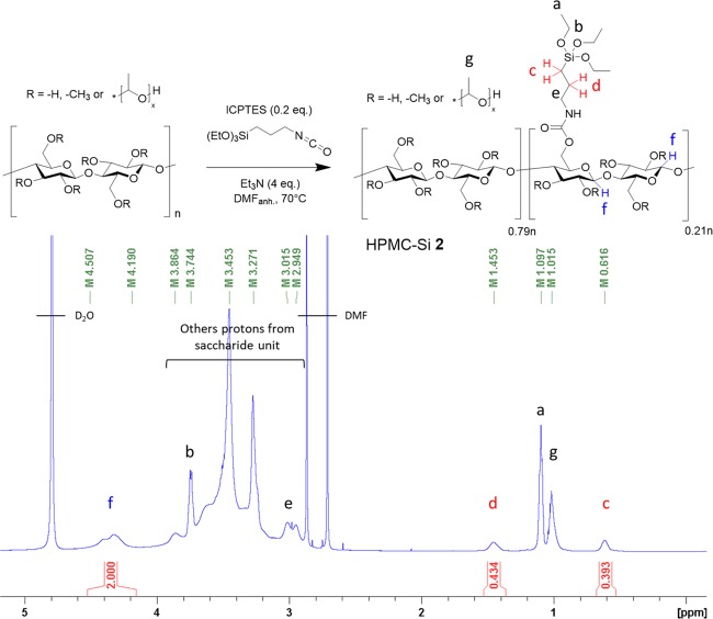
We have performed the reaction of the secondary alcohol functions of HPMC with 3-isocyanatopropyl triethoxysilane (ICPTES) (Figure 1) in anhydrous DMF in the presence of triethylamine at 70 °C. Silylation was completed after 8 h (see the Supporting Information, Figure S1). HPMC-Si was precipitated by the addition of diethyl ether, washed, and dried under vacuum.
Figure 1.
Synthesis (up) and 1H NMR spectrum in D2O (down) of hybrid silylated HPMC, an example for HPMC-Si 2. Anomeric protons are represented in blue (near to 4.5 ppm) and α/β-methylene protons CH2CH2Si in red (near to 0.62 and 1.45 ppm). Attributed protons (a–g) are annotated on the structure.
Different silylation rates were obtained by varying the ICPTES amount from 0.2 to 1 equiv (HPMC-Si 1, 2, and 3) depending on the HPMC repetition unit (332 g/mol). The silylation rate was measured from 1H and 13C quantitative NMR spectra (see the Supporting Information, Figure S2). Briefly, chemical shifts of anomeric protons (in blue, close to 4.5 ppm) and α/β-methylene protons CH2CH2Si (in red, between 0.75 and 1.6 ppm) were determined by two-dimensional (2D) NMR heteronuclear single-quantum correlation (HSQC) experiments (see the Supporting Information, Figure S3). No other proton signal was detected in these chemical shift ranges. The ratio of silylated chains was calculated by quantitative one-dimensional (1D) NMR (Table 1). Thermogravimetric analysis (TGA) performed on HPMC-Si precursors yielded silylation rates in good agreement with those obtained from NMR spectra (see the Supporting Information, Figure S10), ranging from 7 to 56% of silylation per repetition unit (Table 1). It is noteworthy that the reaction yield was ∼50% whatever the equivalent of ICPTES used (e.g., compound 2 prepared with 0.4 equiv of ICPTES showed 21% of silylation compared to a theoretical maximum of 40%). As a control, HPMC-Si 4 was synthesized as previously published23 using (3-glycidyloxypropyl)trimethoxysilane (GPTMS) as a silylation agent in a heterogeneous medium (28% silylation rate) (see the Supporting Information, Figures S6, S8, and S9). As expected, the resulting product was not soluble (in contrast to compounds 1–3) and had to be dissolved at an extremely basic pH (>12.5) and then neutralized to allow the formation of a hydrogel. We suspected premature hydrolysis and condensation of trimethoxysilane of HPMC-Si 4 that occurred during the neutralization step. In addition, this one step cannot guarantee that all GMTPS reacted with HPMC. Indeed, unreacted and hydrolyzed GPTMS can take part in the Si–O–Si covalent network during the sol–gel process.
Table 1. Percent of Silylation of HPMC Determined by 1H NMR, 13C NMR, and TGA.
| % of silylation of HPMC units determined by |
||||
|---|---|---|---|---|
| HPMC-Si | eq. silylating reagenta | 1H NMRb | 13C NMRb | TGA |
| 1 | 0.2 | 9 | 7 | 8 |
| 2 | 0.4 | 21 | 15 | 23 |
| 3 | 1.0 | 48 | 56 | 37 |
| 4 | 0.2 | 28 | 32 | 26 |
Number of equiv related to repeated units of HPMC. ICPTES was used for entries 1–3; GPTMS was used for entry 4.
% = 100 × [area (c + d)/2]/[area f].
To prove this hypothesis, HPMC-Si 4 was dissolved in NaOD/D2O and diffusion-ordered spectroscopy (DOSY) NMR was performed (see the Supporting Information, Figure S7). The spectra clearly show the presence of two components: high-molecular-weight HPMC-Si and a low-molecular-weight component corresponding to hydrolyzed silylating reagent GPTMS, which did not react with the HPMC backbone.
HPMC-Si 2 (∼21% of silylation) was selected as the bioink component. The new average molecular weight of the repetition unit is 384 g/mol (332 × 0.79 + 579.4 × 0.21). This polymer should be able to give one reticulation node of HPMC, each 7.4 nm. This reticulation level was in the same range as the previously described HPMC-Si used for cell encapsulation.18
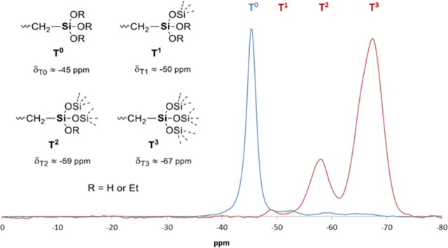
1H NMR and 29Si NMR (see the Supporting Information, Figure S4) showed that HPMC-Si 2 was obtained as a nonhydrolyzed and uncondensed triethoxysilane precursor (Figure 1, 1H NMR signals a and b, and a single peak in the 29Si NMR spectra at −41.5 ppm). The 29Si NMR spectrum of HPMC-Si 4 also shows only one species of silicon at −42.4 ppm (see the Supporting Information, Figure S9). This is because this HPMC-Si has to be dissolved in basic conditions, giving only one silicon species: silanolates. To achieve a more accurate determination of the alkoxysilane state, 29Si solid-state NMR studies were performed on compounds 2 and 4. As expected, one single species of silicon was detected for compound 2 (−45 ppm) and attributed to T0 substructures [−Si(OEt)3]. The absence of Tn (n = 1, 2, and 3) confirmed the absence of hydrolysis and condensation (Figure 2). In contrast, no T0 substructure was detected, while T2 and T3 were predominant in HPMC-Si 4, highlighting the lack of control in HPMC silylation, leading to a nonsoluble HPMC-Si hybrid material.
Figure 2.
Solid-state 29Si NMR of HPMC-Si 2 (blue spectrum) and HPMC-Si 4 (red spectrum). Only T0 species are observed for HPMC-Si 2 (no Si–O–Si species), while T1, T2, and T3 species are observed for HPMC-Si 4.
Three different conditions were used to catalyze the sol–gel formation of hydrogel from HPMC-Si (Table 2).
Table 2. Gelation Time as a Function of the Catalyst for an HPMC-Si 2 Hydrogel (13.5 wt %).
| condition | NaF (g/L) | glycine (g/L) | gel point (min) | macroscopic gel point (min) |
|---|---|---|---|---|
| A | 0.3 | 33 | 206 | |
| B | 0.1 | 34 | 315 | |
| C | 0.1 | 10 | 30 | 143 |
HPMC-Si 2 was poured in pH 7.4 Dulbecco’s phosphate-buffered saline (DPBS) and stirred for 12 h. Then, a solution of NaF and/or glycine (conditions A, B, or C) was added to obtain a final HPMC-Si concentration of 135 g/L (13.5 wt %, 0.35 M of RU; a volume of 5–20 mL was commonly used). The viscous solution was quickly centrifuged to eliminate air bubbles trapped during dissolution.
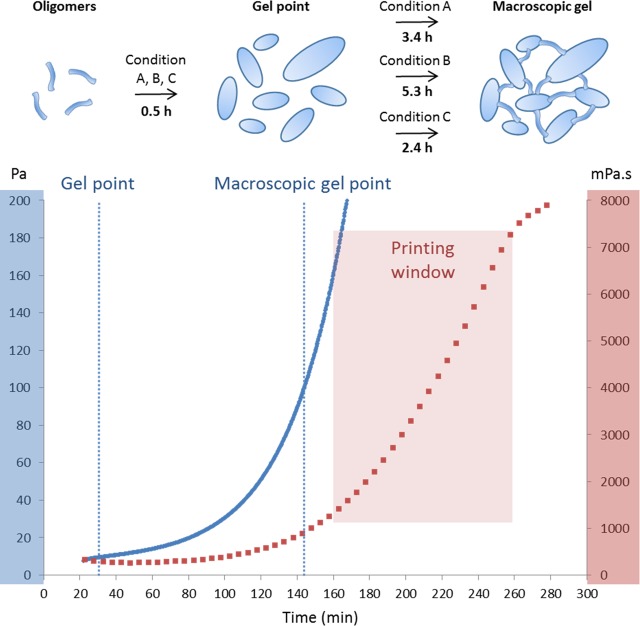
In all cases, hydrolysis and condensation allowed the formation of Si–O–Si bridges and the formation of a translucent hybrid hydrogel. Storage (or elastic shear) modulus G′ and loss modulus G″ were recorded during gelation by Small-Amplitude Oscillatory Shear (SAOS) experiments on an HR-2 rheometer. Two characteristic G′ values were pointed out: the “gel point”, which corresponded to the intersection between G′ and G″ curves at which the solution still flowed, and the “macroscopic gel point”, at G′ = 100 Pa, where the solution no longer flowed and the hydrogel was formed.
The gel point was found to be nearly the same for the three conditions (see the Supporting Information, Figures S11–S13). This point can be explained by the formation of large colloidal particles inducing an increase of the storage modulus. Otherwise, the macroscopic gel point time was greatly impacted by varying the NaF concentration: 206 min for condition A and 315 min for condition B. More interestingly, glycine (condition C) acts as a cocatalyst for the cross-linking between the colloids and speeds up gelation (macroscopic gel point at 143 min) while keeping the NaF concentration as low as 0.1 mg/mL.
To determine the optimal printing window, extrusion-printing assays were performed using a BioBots 3D device. Simultaneously, the evolution of viscosity over time was recorded using an SV-10 sine-wave vibro viscometer (see the Supporting Information, Figure S15). A continuous filament of HPMC-Si could be ideally extruded between 160 and 260 min (i.e., just after reaching the macroscopic gel point). Indeed, before 160 min, HPMC-Si flowed after extrusion. On the other hand, after 260 min, the hydrogel was too stiff and led to irregular, broken pieces of ribbons going out of the nozzle. This “printing window” corresponded to viscosity values ranging from 1500 to 7300 mPa s (Figure 3).
Figure 3.
Schematic representation of the catalysis process and gelation times as a function of catalyst condition (up) and HPMC-Si 2 hydrogel (13.5 wt %) gelation in condition C, recorded as a function of time (down). Viscosity, red trace; storage modulus (G′), blue trace. The printing window is experimentally set between 160 and 260 min.
Macroindentation was performed on the HPMC-Si 2 hydrogel. This method provides a way to characterize both the compression elastic properties (compressive strain: ε) and the mechanical resistance of the soft material (normal stress: σ). In the first moments of deformation (below 5% deformation), the linear low-strain regime provides a way to define an apparent elastic modulus (E* = δσ/δε) and, after calculation, Young’s modulus E.25,26 This value gives information about the rigidity of the hydrogel. Interestingly, HPMC-Si 2 Young’s modulus was found to be in the same range as that for soft biological tissues (see the Supporting Information, Figure S14).27
The network mesh size (ξ), which monitors the physicochemical properties of the hydrogel (rigidity, water displacement, etc.), was calculated by rheological28 and swelling studies,29 yielding values of 4.8 and 1.1 nm, respectively (Table 3).
Table 3. Physicochemical Values of an HPMC-Si 2 Hydrogel (13.5 wt %).
| σmax. (kPa) | εmax. (%) | E (kPa) | ξrheo. (nm) | ξswel. (nm) | ξcryo (nm) |
|---|---|---|---|---|---|
| 667 ± 4 | 66 ± 2 | 99 ± 15 | 4.8 ± 0.7 | 1.1 ± 0.1 | 50–200 |
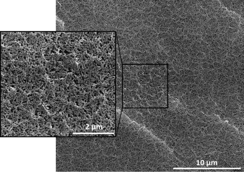
Cryo-SEM analyses were also performed. As shown in Figure 4, the network was homogeneous, and the pore size was between 50 and 200 nm. When compared with the mesh size calculated by rheology and swelling, cryo-SEM results displayed a significant magnitude difference (Table 3).
Figure 4.
Cryo-SEM images of the HPMC-Si 2 hydrogel (13.5 wt %).
We assumed that the structure observed in cryo-SEM analysis was due to a macromolecular arrangement between HPMC chains, while cross-linking between silanes (and then the mesh size) was at a nanometric scale, nondetectable by this method. Thereby, we assumed that cells (up to 20 μm) could be entrapped in the hydrogel network but likely could not proliferate.
One additional advantage of the sol–gel process for bioink design was the ease of further network covalent functionalization. We already demonstrated that additional peptide ligands could be added on PEG hydrogels to favor cell adhesion.19
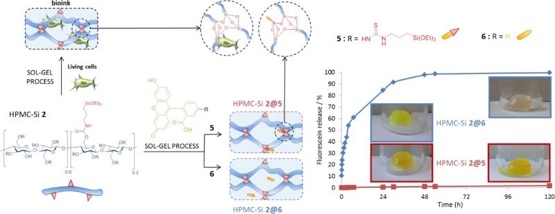
As a proof of concept, we mixed triethoxysilyl fluorescein205 with HPMC-Si 2 to prepare fluorescent hydrogels (HPMC-Si 2@5). As a control experiment, a hydrogel was prepared using the same concentration (i.e., 1.7 mM) of fluorescein 6 but noncovalently entrapped within the hydrogel network (HPMC-Si 2@6). The resulting hydrogels were then placed in phosphate buffer (10 mL), and the fluorescein release was monitored by HPLC. As expected, almost no fluorescein release was observed on the hybrid fluorescein 5 that was covalently grafted on the network by Si–O–Si bridges, even after 120 h (<1%). In contrast, all fluorescein from material 6 was released after 48 h (Figure 5).
Figure 5.
Multifunctional hybrid hydrogel: bioink and fluorescein release from hybrid hydrogels HPMC-Si 2@5 and HPMC-Si 2@6. Silylated fluorescein 5 (red curve) and fluorescein 6 (blue curve) were added to HPMC-Si 2 solution from the start. All fluorescein 6 was released after 48 h in PBS, while silylated fluorescein 5 remained in the hydrogel after 120 h.
Finally, a bioink containing hMSC (1.106 cells/mL), HPMC-Si 2 (13.5 wt %), and catalysts (condition C) in PBS was bioprinted. It is noteworthy that at this concentration, the cells have not sedimented. Briefly, the bioink was placed in a syringe and kept at 37 °C for 160 min (i.e., according to the printing window) before writing a 6-layer grid-patterned scaffold (Figure 6). As a control, the bioink was also casted in a culture plate without going through the nozzle.
Figure 6.
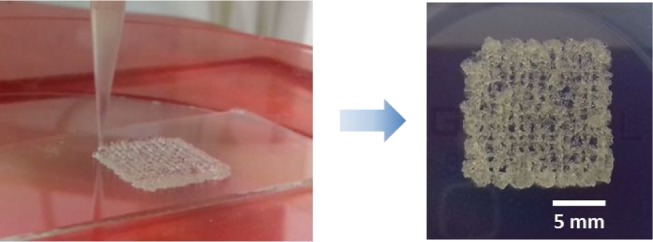
Grid-patterned scaffold of the HPMC-Si 2 hydrogel (13.5 wt %) containing cells. Resolution can be improved by printing at a higher viscosity or at a lower pressure to extrude a thinner filament.
Once printed, network reticulation continues for 24 h at 37 °C. The G′ increases from 0.16 kPa during printing to 38 kPa after 24 h. The latest value was calculated from Young’s modulus at 24 h: G′ = E/[2 × (1 + ν)]. To avoid drying of the hydrogel, PBS was added in empty wells at the periphery of the culture plate, which contained the cell-embedded hydrogels. The printing resolution was not optimal but remained acceptable and comparable to other extruded scaffolds obtained from photo-cross-linked hydrogels made with alginate or a decellularized extracellular matrix with poly(ethylene glycol) (PEG).30,31
After 24 h at 37 °C, the culture medium (αMEM with 10% fetal calf serum, 100 μg/mL penicillin/streptomycin, 2 mM glutamine, 1 ng/mL basic fibroblast growth factor) was added to the cells. hMSCs were cultured for 7 days with medium change after 3 days of culture. At days 1 and 7, the viability of hMSC was evaluated using a live/dead cell imaging kit (labeling for 15 min at room temperature) and confocal microscopy.
One day after inclusion in the hydrogel, most of the hMSCs were alive, as indicated by the green color, and survived for at least the follow-up 7 days (Figure 7A,C). It is worth noting that 3D printing did not alter hMSC survival in the hydrogel since a majority of green living cells were observed at day 1 and till day 7 (Figure 7B,D).
Figure 7.
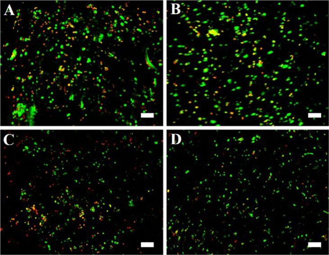
Viability of hMSCs in the HPMC-Si 2 hydrogel (13.5 wt %). hMSCs were labeled with live/dead staining at D1 (A, B) or D7 (C, D) after pipetting (A, C) or 3D printing (B, D). Images show the maximal projection of the z-axis, and scale bars represent 100 μm.
Conclusions
This study describes the first example of a cell-containing hydrogel scaffold obtained by 3D bioprinting using the sol–gel process. Beyond the example of HPMC, this strategy is generic enough to be applied to any type of multisilylated biopolymer as a network precursor polymerizable block. Advantageously, monosilylated organic molecules such as peptide ligands, drugs, imaging probes, and cleavable linkers could be added to the network precursors along with the cells to prepare a wide range of different bioinks.
Acknowledgments
This work was funded by the ANR (Agence Nationale de la Recherche) and the French National Research Agency (ANR-16- CE18-0003).
Supporting Information Available
The Supporting Information is available free of charge at https://pubs.acs.org/doi/10.1021/acsomega.9b03100.
Materials and methods, precursor synthesis and characterization, and hydrogel synthesis and characterization, including synthesis of HPMC-Si 2 and HPMC-Si 4, 1H NMR and 13C NMR kinetic studies, 2D NMR HSQC, 29Si NMR spectrum, 1H DOSY NMR spectrum, TGA curves of HPMC, G′ and G″ moduli, stress–strain relations, viscosity of a HPMC-Si 2 solution, symbol names and values used for Young’s modulus calculation and mesh size calculation, and calibration curve obtained for fluorescein (PDF)
The authors declare no competing financial interest.
Supplementary Material
References
- Hoque M. E.; Chuan Y. L.; Pashby I. Extrusion Based Rapid Prototyping Technique: An Advanced Platform for Tissue Engineering Scaffold Fabrication. Biopolymers 2012, 97, 83–93. 10.1002/bip.21701. [DOI] [PubMed] [Google Scholar]
- Blaeser A.; Campos D. F. D.; Fischer H. 3D Bioprinting of Cell-Laden Hydrogels for Advanced Tissue Engineering. Curr. Opin. Biomed. Eng. 2017, 2, 58–66. 10.1016/j.cobme.2017.04.003. [DOI] [Google Scholar]
- Huang Y.; Zhang X.-F.; Gao G.; Yonezawa T.; Cui X. 3D Bioprinting and the Current Applications in Tissue Engineering. Biotechnol. J. 2017, 12, 1600734 10.1002/biot.201600734. [DOI] [PubMed] [Google Scholar]
- Jian H.; Wang M.; Wang S.; Wang A.; Bai S. 3D Bioprinting for Cell Culture and Tissue Fabrication. Bio-Des. Manuf. 2018, 1, 45–61. 10.1007/s42242-018-0006-1. [DOI] [Google Scholar]
- Guvendiren M.; Molde J.; Soares R. M. D.; Kohn J. Designing Biomaterials for 3D Printing. ACS Biomater. Sci. Eng. 2016, 2, 1679–1693. 10.1021/acsbiomaterials.6b00121. [DOI] [PMC free article] [PubMed] [Google Scholar]
- Bajaj P.; Schweller R. M.; Khademhosseini A.; West J. L.; Bashir R. 3D Biofabrication Strategies for Tissue Engineering and Regenerative Medicine. Annu. Rev. Biomed. Eng. 2014, 16, 247–276. 10.1146/annurev-bioeng-071813-105155. [DOI] [PMC free article] [PubMed] [Google Scholar]
- Malda J.; Visser J.; Melchels F. P.; Jüngst T.; Hennink W. E.; Dhert W. J. A.; Groll J.; Hutmacher D. W. 25th Anniversary Article: Engineering Hydrogels for Biofabrication. Adv. Mater. 2013, 25, 5011–5028. 10.1002/adma.201302042. [DOI] [PubMed] [Google Scholar]
- Valot L.; Martinez J.; Mehdi A.; Subra G. Chemical Insights into Bioinks for 3D Printing. Chem. Soc. Rev. 2019, 48, 4049–4086. 10.1039/C7CS00718C. [DOI] [PubMed] [Google Scholar]
- Zhang Y.; Yu Y.; Akkouch A.; Dababneh A.; Dolati F.; Ozbolat I. T. In Vitro Study of Directly Bioprinted Perfusable Vasculature Conduits. Biomater. Sci. 2015, 3, 134–143. 10.1039/C4BM00234B. [DOI] [PMC free article] [PubMed] [Google Scholar]
- Daly A. C.; Critchley S. E.; Rencsok E. M.; Kelly D. J. A Comparison of Different Bioinks for 3D Bioprinting of Fibrocartilage and Hyaline Cartilage. Biofabrication 2016, 8, 045002 10.1088/1758-5090/8/4/045002. [DOI] [PubMed] [Google Scholar]
- Liang H.; He J.; Chang J.; Zhang B.; Li D. Coaxial Nozzle-Assisted Electrohydrodynamic Printing for Microscale 3D Cell-Laden Constructs. Int. J. Bioprint. 2017, 4, 1–8. 10.18063/ijb.v4i1.127. [DOI] [PMC free article] [PubMed] [Google Scholar]
- Park J.; Lee S. J.; Chung S.; Lee J. H.; Kim W. D.; Lee J. Y.; Park S. A. Cell-Laden 3D Bioprinting Hydrogel Matrix Depending on Different Compositions for Soft Tissue Engineering: Characterization and Evaluation. Mater. Sci. Eng., C 2017, 71, 678–684. 10.1016/j.msec.2016.10.069. [DOI] [PubMed] [Google Scholar]
- Axpe E.; Oyen M. L. Applications of Alginate-Based Bioinks in 3D Bioprinting. Int. J. Mol. Sci. 2016, 17, 1976 10.3390/ijms17121976. [DOI] [PMC free article] [PubMed] [Google Scholar]
- Xu F.; Moon S. J.; Emre A. E.; Turali E. S.; Song Y. S.; Hacking S. A.; Nagatomi J.; Demirci U. A Droplet-Based Building Block Approach for Bladder Smooth Muscle Cell (SMC) Proliferation. Biofabrication 2010, 2, 014105 10.1088/1758-5082/2/1/014105. [DOI] [PubMed] [Google Scholar]
- Rhee S.; Puetzer J. L.; Mason B. N.; Reinhart-King C. A.; Bonassar L. J. 3D Bioprinting of Spatially Heterogeneous Collagen Constructs for Cartilage Tissue Engineering. ACS Biomater. Sci. Eng. 2016, 2, 1800–1805. 10.1021/acsbiomaterials.6b00288. [DOI] [PubMed] [Google Scholar]
- Michael S.; Sorg H.; Peck C.-T.; Koch L.; Deiwick A.; Chichkov B.; Vogt P. M.; Reimers K. Tissue Engineered Skin Substitutes Created by Laser-Assisted Bioprinting Form Skin-Like Structures in the Dorsal Skin Fold Chamber in Mice. PLoS One 2013, 8, e57741 10.1371/journal.pone.0057741. [DOI] [PMC free article] [PubMed] [Google Scholar]
- Ng W. L.; Goh M. H.; Yeong W. Y.; Naing M. W. Applying Macromolecular Crowding to 3D Bioprinting: Fabrication of 3D Hierarchical Porous Collagen-Based Hydrogel Constructs. Biomater. Sci. 2018, 6, 562–574. 10.1039/C7BM01015J. [DOI] [PubMed] [Google Scholar]
- Echalier C.; Jebors S.; Laconde G.; Brunel L.; Verdié P.; Causse L.; Bethry A.; Legrand B.; Van Den Berghe H.; Garric X.; et al. Sol-Gel Synthesis of Collagen-Inspired Peptide Hydrogel. Mater. Today 2017, 20, 59–66. 10.1016/j.mattod.2017.02.001. [DOI] [Google Scholar]
- Echalier C.; Pinese C.; Garric X.; Van Den Berghe H.; Jumas Bilak E.; Martinez J.; Mehdi A.; Subra G. Easy Synthesis of Tunable Hybrid Bioactive Hydrogels. Chem. Mater. 2016, 28, 1261–1265. 10.1021/acs.chemmater.5b04881. [DOI] [Google Scholar]
- Echalier C.; Levato R.; Mateos-Timoneda M. A.; Castano O.; Dejean S.; Garric X.; Pinese C.; Noel D.; Engel E.; Martinez J.; et al. Modular Bioink for 3D Printing of Biocompatible Hydrogels: Sol-Gel Polymerization of Hybrid Peptides and Polymers. RSC Adv. 2017, 7, 12231–12235. 10.1039/C6RA28540F. [DOI] [Google Scholar]
- Valot L.; Maumus M.; Noël D.; Montheil T.; Martinez J.; Mehdi A.; Subra G. Biocompatible Catalysis of Sol-Gel Process for the Synthesis of Hydrogels. ChemPlusChem 2019, 84 (11), 1720–1729. 10.1002/cplu.201900509. [DOI] [PubMed] [Google Scholar]
- Vinatier C.; Gauthier O.; Fatimi A.; Merceron C.; Masson M.; Moreau A.; Moreau F.; Fellah B.; Weiss P.; Guicheux J. An Injectable Cellulose-Based Hydrogel for the Transfer of Autologous Nasal Chondrocytes in Articular Cartilage Defects. Biotechnol. Bioeng. 2009, 102, 1259–1267. 10.1002/bit.22137. [DOI] [PubMed] [Google Scholar]
- Bourges X.; Weiss P.; Daculsi G.; Legeay G. Synthesis and General Properties of Silated-Hydroxypropyl Methylcellulose in Prospect of Biomedical Use. Adv. Colloid Interface Sci. 2002, 99, 215–228. 10.1016/S0001-8686(02)00035-0. [DOI] [PubMed] [Google Scholar]
- Ciccione J.; Jia T.; Coll J.-L.; Parra K.; Amblard M.; Jebors S.; Martinez J.; Mehdi A.; Subra G. Unambiguous and Controlled One-Pot Synthesis of Multifunctional Silica Nanoparticles. Chem. Mater. 2016, 28, 885–889. 10.1021/acs.chemmater.5b04398. [DOI] [Google Scholar]
- Hayes W. C.; Keer L. M.; Herrmann G.; Mockros L. F. A Mathematical Analysis for Indentation Tests of Articular Cartilage. J. Biomech. 1972, 5, 541–551. 10.1016/0021-9290(72)90010-3. [DOI] [PubMed] [Google Scholar]
- Haider M. A.; Holmes M. H. A Mathematical Approximation for the Solution of a Static Indentation Test. J. Biomech. 1997, 30, 747–751. 10.1016/S0021-9290(97)00024-9. [DOI] [PubMed] [Google Scholar]
- McKee C. T.; Last J. A.; Russell P.; Murphy C. J. Indentation Versus Tensile Measurements of Young’s Modulus for Soft Biological Tissues. Tissue Eng., Part B 2011, 17, 155–164. 10.1089/ten.teb.2010.0520. [DOI] [PMC free article] [PubMed] [Google Scholar]
- Pagels R. F.; Prud’homme R. K. Polymeric Nanoparticles and Microparticles for the Delivery of Peptides, Biologics, and Soluble Therapeutics. J. Controlled Release 2015, 219, 519–535. 10.1016/j.jconrel.2015.09.001. [DOI] [PubMed] [Google Scholar]
- Canal T.; Peppas N. A. Correlation between Mesh Size and Equilibrium Degree of Swelling of Polymeric Networks. J. Biomed. Mater. Res. A 1989, 23, 1183–1193. 10.1002/jbm.820231007. [DOI] [PubMed] [Google Scholar]
- Ooi H. W.; Mota C.; ten Cate A. T.; Calore A.; Moroni L.; Baker M. B. Thiol–Ene Alginate Hydrogels as Versatile Bioinks for Bioprinting. Biomacromolecules 2018, 19, 3390–3400. 10.1021/acs.biomac.8b00696. [DOI] [PMC free article] [PubMed] [Google Scholar]
- Skardal A.; Devarasetty M.; Kang H.-W.; Mead I.; Bishop C.; Shupe T.; Lee S. J.; Jackson J.; Yoo J.; Soker S.; Atala A. A Hydrogel Bioink Toolkit for Mimicking Native Tissue Biochemical and Mechanical Properties in Bioprinted Tissue Constructs. Acta Biomater. 2015, 25, 24–34. 10.1016/j.actbio.2015.07.030. [DOI] [PubMed] [Google Scholar]
Associated Data
This section collects any data citations, data availability statements, or supplementary materials included in this article.


