Abstract
Background
The anatomical tachycardia circuit of sinoatrial node reentrant tachycardia (SANRT) has not been well clarified. This study aimed to elucidate the tachycardia circuit of SANRT.
Methods and Results
Exit and entrance of the intranodal sinoatrial node conduction (I‐SANC) of the reentry circuit were identified in 15 SANRT patients. After identifying the earliest atrial activation site (EAAS) during the tachycardia (EAAS‐SANRT), rapid atrial pacing was delivered from multiple atrial sites to identify the entrainment pacing site where manifest entrainment and orthodromic capture of the EAAS‐SANRT were demonstrated. Radiofrequency energy was then delivered starting at a site 2 cm proximal to the EAAS‐SANRT in the direction of the entrainment pacing site and gradually advanced toward the EAAS‐SANRT until tachycardia termination to localize the I‐SANC entrance. The EAAS‐SANRT was orthodromically captured by pacing delivered from the distal coronary sinus (n=7), high posteroseptal right atrium (n=2), low posteroseptal right atrium (n=2), low anterolateral right atrium (n=2), or coronary sinus ostium (n=2). Radiofrequency energy delivery to the entrance of the I‐SANC, 10.4±2.8 mm away from the EAAS‐SANRT, terminated tachycardia immediately after onset of energy delivery (3.4±2.3 seconds). The successful ablation site was located further from the EAAS during sinus rhythm (EAAS‐sinus) than the EAAS‐SANRT (12.8±4.5 versus 7.2±3.1 mm; P<0.0001).
Conclusions
The reentry circuit of SANRT was composed of the entrance and exit of the I‐SANC being located at distinctly different anatomical sites. SANRT was eliminated by radiofrequency energy delivered to the I‐SANC entrance, which was further from the EAAS‐sinus than I‐SANC exit.
Keywords: atrial tachycardia, catheter ablation, mapping
Subject Categories: Arrhythmias, Electrophysiology
Clinical Perspective
What Is New?
We demonstrated manifest entrainment during the sinoatrial node reentrant tachycardia (SANRT) and showed the precise anatomical reentrant tachycardia circuit for the first time.
SANRT was terminated by a radiofrequency energy application delivered to the entrance of the reentry circuit, distant from the exit of the reentry circuit.
The reentry circuit was suggested to involve the perinodal atrium according to the findings of manifest entrainment and the results of the catheter ablation.
What Are the Clinical Implications?
The entrance of the SANRT reentry circuit was located further from the earliest atrial activation site during sinus rhythm than from the exit of the SANRT reentry circuit.
Thus, an entrance site ablation may be an alternative and safer therapeutic option than targeting the earliest atrial activation site during SANRT to avoid sinus node dysfunction.
Sinoatrial node reentrant tachycardia (SANRT) is an uncommon type of atrial tachycardia originating from the sinoatrial node region. Barker et al were the first to propose that reentry could occur within the sinus node.1 Han et al demonstrated the existence of sinoatrial reentrant echo beats in a superfused isolated rabbit right atrial preparation.2 Allessie and Bonke reported a study suggesting confinement of the reentry circuit to the sinus node in the rabbit heart.3 Glukhov et al examined the sinoatrial node reentry circuit in a canine model using high‐resolution optical mapping.4 They revealed both a sinoatrial macro‐reentry involving the atrial myocardium and a micro‐reentry confined to within the sinoatrial node.4 In humans, Narura first described sustained SANRT, and his criteria to diagnose the SANRT are still valid.5 However, the details of the reentry circuit in patients with SANRT are still controversial to this day, because it is practically impossible to record the electrical activity of the human sinoatrial node directly by the currently used electrode catheters. Verapamil‐sensitive atrial tachycardia arising from the atrioventricular annulus has electrophysiological features similar to SANRT, because a calcium‐channel–dependent tissue forms the slow conduction zone of the reentry circuit.6, 7, 8 Recently, we have shown that the entrance of the slow conduction zone in verapamil‐sensitive atrial tachycardia arising from the atrioventricular annulus can be identifiable and selectively ablated using the entrainment method.6, 7, 8 Therefore, we attempted to localize the entrance of the intranodal sinoatrial node conduction (I‐SANC) in the SANRT reentry circuit using the same entrainment method and elucidated the anatomical reentry circuit of SANRT.
Methods
This study was approved by the hospital institutional review committee, and written informed consent was obtained from each patient. The data, analytical methods, and study materials will not be made available to other researchers for purposes of reproducing the results or replicating the procedure.
Study Population
Fifteen consecutive patients with SANRT of 359 patients with supraventricular tachycardia who were referred for radiofrequency catheter ablation from 2009 to 2019 were included in this study. There were 6 men and 9 women (mean age, 69 years; range, 59–76; Table).
Table 1.
Electrophysiological Characteristics of SANRT
| Pt | Age/Sex | TCL (ms) | Location of the EAAS During SANRT Relative to the EAAS During SR | Manifest entrainment Pacing Site | Successful RF Site Relative to the EAAS During SANRT | Distance Between the EAAS During SANRT and Successful RF Site (mm) | Activation Time Between the EAAS During SANRT and Successful RF Site (ms) | Interval From the RF Onset to Termination (ms) |
|---|---|---|---|---|---|---|---|---|
| 1 | 72/F | 465 | AI to EAAS during SR | Distal CS | P‐EAAS | 10 | 15 | 0.9 |
| 2 | 74/F | 510 | AI to EAAS during SR | Distal CS | P‐EAAS | 9 | 15 | 6.9 |
| 3 | 74/M | 435 | I to EAAS during SR | High‐PS RA | P‐EAAS | 10 | 15 | 0.9 |
| 4 | 73/F | 520 | AI to EAAS during SR | Distal CS | P‐EAAS | 16 | 15 | 0.6 |
| 5 | 76/M | 370 | AI to EAAS during SR | Distal CS | P‐EAAS | 9 | 10 | 4.0 |
| 6 | 67/F | 440 | S to EAAS during SR | High‐PS RA | P‐EAAS | 17 | 10 | 3.3 |
| 7 | 64/F | 440 | PI to EAAS during SR | Low‐PS RA | PI‐EAAS | 12 | 15 | 1.6 |
| 8 | 63/M | 420 | A to EAAS during SR | CSOS | PI‐EAAS | 8 | 10 | 3.3 |
| 9 | 75/F | 540 | AI to EAAS during SR | Low‐PS RA | PI‐EAAS | 12 | 10 | 3.0 |
| 10 | 72/F | 420 | I to EAAS during SR | Distal CS | P‐EAAS | 10 | 18 | 1.8 |
| 11 | 59/M | 430 | P to EAAS during SR | Low‐AL RA | I‐EAAS | 9 | 16 | 3.1 |
| 12 | 66/M | 600 | S to EAAS during SR | CSOS | PI‐EAAS | 8 | 14 | 2.9 |
| 13 | 76/F | 510 | S to EAAS during SR | Distal CS | P‐EAAS | 9 | 15 | 7.4 |
| 14 | 68/F | 455 | I to EAAS during SR | Distal CS | P‐EAAS | 8 | 20 | 4.0 |
| 15 | 61/M | 600 | I to EAAS during SR | Low‐AL RA | I‐EAAS | 9 | 20 | 7.5 |
| 69±6 | 477.0±67.4 | 10.4±2.8 | 14.5±3.4 | 3.4±2.3 |
Data are the mean±SD. A indicates anterior; AI, anteroinferior; AL, anterolateral; AS, anteroseptal; CS, coronary sinus; CSOS, coronary sinus ostium; EAAS, earliest atrial activation site; I, inferior; P, posterior; PI, posteroinferior; PS, posteroseptal; Pt, patient; RA, right atrium; RF, radiofrequency ablation; S, superior; SANRT, sinoatrial node reentrant tachycardia; SR, sinus rhythm; TCL, tachycardia cycle length.
Electrophysiological Study
Two 6‐Fr quadripolar electrode catheters (St. Jude Medical, St. Paul, MN) were positioned in the His bundle region and right ventricular apex. A 6‐Fr 20‐pole electrode catheter (St. Jude Medical) was introduced into the coronary sinus (CS). A 7‐Fr 4 mm‐tip, deflectable quadripolar electrode catheter with a 2‐mm interelectrode distance (Japan Lifeline, Tokyo, Japan) was advanced into the right atrium (RA) for atrial mapping, pacing, and ablation. Bipolar electrograms were filtered between 50 and 600 Hz and recorded along with the surface ECG using a polygraph (EP‐workmate; EP Med. Systems, Inc., Mt Arlington, NJ). Atrial and ventricular pacing was performed using a cardiac stimulator (SEC‐4103; Nihon Kohden, Tokyo, Japan). The diagnosis of SANRT required the following criteria5, 9: (1) atrial activation sequence originating from the high lateral RA and similar to that during sinus rhythm; (2) P‐wave configuration on the 12‐lead ECG during the tachycardia similar to the P‐wave configuration during sinus rhythm; (3) reproducible initiation and termination of the tachycardia by atrial burst and/or premature stimulation; and (4) termination with adenosine triphosphate or with maneuvers that increase the vagal tone.
Identification of the Entrance of the I‐SANC
After the right atriography in the biplane view, the RA was mapped during sinus rhythm using a contact mapping system (EnSite NavX; St. Jude Medical), and the location of the earliest atrial activation site (EAAS) during sinus rhythm was identified. The RA was mapped again during the SANRT, to identify the location of the EAAS during the tachycardia. The location of the EAAS during SANRT was expressed relative to the EAAS during sinus rhythm. The proximity of the I‐SANC in the reentry circuit of the SANRT was identified utilizing an entrainment technique.10 While recording the contact atrial electrogram at the EAAS during SANRT, rapid atrial pacing at a rate 5 beats/min faster than the tachycardia rate was delivered to demonstrate manifest entrainment and orthodromic capture of the EAAS.6, 7, 8, 11 Rapid pacing was delivered from 9 sites in the RA and CS: high anterolateral RA, high posterolateral RA, high anteroseptal RA, high posteroseptal RA, low anterolateral RA, low posterolateral RA, low posteroseptal RA, CS ostium, and, distal CS. When the entrance site of the reentry circuit was located posterior to the sinoatrial node, demonstration of manifest entrainment by pacing from the RA was difficult because the entrance site was close to the left atrium. In those cases, we attempted to demonstrate the manifest entrainment by the pacing delivered from the distal CS, assuming that the orthodromic capture of the EAAS during SANRT could be obtained by the stimulated wave front propagating through Bachman's bundle. When manifest entrainment with orthodromic capture of the electrogram at the EAAS was demonstrated, the pacing site was considered to be proximal to the I‐SANC of the reentry circuit6, 7, 8, 12 (Figure 1). Manifest entrainment was defined as when constant fusion of the surface P waves was demonstrated, and as when the orthodromic capture of the electrogram at the EAAS with a long conduction time and antidromic capture with direct activation by pacing showing different electrogram morphologies were both observed during 1 paced beat during pacing except for the last entrained beat6, 7, 8, 10, 12 (Figure 1). After identification of a site proximal to the I‐SANC (entrainment pacing site, Figure 1), radiofrequency energy was delivered starting at a site 2 cm away from the EAAS in the direction of the entrainment pacing site because this site was considered to be proximally close to the entrance of the I‐SANC (Figure 1). A current of 15 to 20 W was delivered initially for 10 seconds with the temperature limit set to 55°C using a radiofrequency energy generator (CABL‐IT; Central Inc., Ichikawa, Chiba). When the SANRT was not terminated within 10 seconds, the energy application site was advanced in a step‐wise fashion by 2 to 3 mm toward the EAAS under the guidance of the EnSite anatomical map, until the tachycardia terminated in order to identify the entrance of the I‐SANC of the reentry circuit (Figure 1). If the SANRT terminated within 10 seconds after onset of energy delivery, then we continued the energy delivery up to 30 to 60 seconds at that site.
Figure 1.
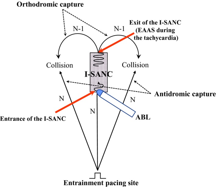
Schematic drawing of the method for identification of the entrance of the intranodal sinoatrial node conduction (I‐SANC) using entrainment and ablation techniques. ABL indicates ablation catheter; EAAS, earliest atrial activation site.
Analysis of the Anatomical Reentry Circuit During the SANRT
To define the anatomical reentry circuit during the SANRT, the length of the I‐SANC, which was expressed by the distance from the EAAS during SANRT (exit of I‐SANC) to the successful ablation site (entrance of I‐SANC), was measured. The atrial activation time between the EAAS during SANRT (exit of I‐SANC) and the successful ablation site (entrance of the I‐SANC) during the tachycardia was also measured. To define the relative location of the SANRT reentry circuit in relation to the EAAS during sinus rhythm, the distance from the EAAS during sinus rhythm to the EAAS during the SANRT (exit of I‐SANC) and that from the EAAS during sinus rhythm to the successful ablation site (entrance of I‐SANC) were measured.
Statistical Analysis
Values are expressed as the mean±SD. Differences between clinical variables and electrophysiological parameters were analyzed using a paired Student t test for the quantitative data. A value of P<0.05 was considered significant.
Statement of responsibility
The authors had full access to the data and take responsibility for their integrity. All authors have read and agree with the manuscript for this article as written.
Results
In all patients, a tachycardia was induced and terminated by atrial rapid and extrastimulus pacing, and an inverse relationship between the A1A2 and A2Ae was observed during induction of the SANRT by atrial extrastimulus pacing. Initiation and termination of the tachycardia by atrial burst and/or premature stimulation were performed at least 3 times to confirm its reproducibility in all patients. Isoproterenol was used for induction of SANRT in 3 patients (patients 4, 5, and 10), but was not in the remaining 12. In those 3 patients, contact mapping during sinus rhythm and SANRT was performed during an isoproterenol administration. Intravenous administration of adenosine triphosphate (2.5–5.0 mg) terminated the tachycardia in all 15 patients. Vagal maneuvers were performed in 5 patients, and the SANRT was terminated in all 5 patients. Mean tachycardia cycle length was 477.0±67.4 ms (range, 370–600; Table).
Location of the EAAS During SANRT Relative to the EAAS During Sinus Rhythm
The EAAS during SANRT was observed in the vicinity of the EAAS during sinus rhythm in all patients (Table). The distance between the EAAS during sinus rhythm and EAAS during SANRT was 7.2±3.1 mm (range, 3–14). The EAAS during SANRT was located in the anterior (n=1), posterior (n=1), superior (n=3), inferior (n=4), anteroinferior (n=5), and posteroinferior (n=1) portion of the EAAS during sinus rhythm, respectively (Table).
Manifest Entrainment and Catheter Ablation
Manifest entrainment was demonstrated by rapid atrial pacing delivered from 1 specific site in each patient, being associated with the orthodromic capture of the earliest atrial electrogram (Table). Manifest entrainment was demonstrated by pacing from the distal CS (n=7), high posteroseptal RA (n=2), low posteroseptal RA (n=2), low anterolateral RA (n=2), and CS ostium (n=2), respectively (Table). In all patients, the SANRT was terminated by an application of radiofrequency energy, which was delivered to a site proximal to the EAAS during the SANRT in the direction of the manifest entrainment pacing site (Table). In 9 patients (patients 1–6, 10, 13, and 14), the successful ablation site (ie, entrance of I‐SANC) was located in the posterior portion of the EAAS during the SANRT (Table). The successful ablation site was located at the posteroinferior portion of the EAAS during the SANRT in 4 patients (patients 7–9 and 12; Table) and at the inferior portion of the EAAS during the SANRT in the remaining 2 patients (patients 11 and 15; Table). The distance between the EAAS during SANRT (exit of I‐SANC) and the successful ablation site (entrance of I‐SANC) was 10.4±2.8 mm (8–16; Table). Onset of the atrial electrogram at the successful ablation site occurred 14.5±3.4 ms later than that of the EAAS during the SANRT (Table). The SANRT was terminated immediately after onset of radiofrequency energy delivery (3.4±2.3 seconds; Table). The mean number of radiofrequency applications required for a successful ablation was 4±2. After termination of the tachycardia by the initial successful ablation, a reinduction of the tachycardia was attempted, but no reinduction of SANRT was observed in any of the patients. The ablation was not associated with any complications. During a mean follow‐up period of 53±43 months (range, 12–122), neither tachycardia recurrence nor sinus node dysfunction were observed.
Figure 2 shows the tracing during manifest entrainment in patient 7. The EAAS during the SANRT was observed in the high right atrium (HRA; 7–8; Figure 2). During pacing from the low posteroseptal RA, the EAAS (HRA 7–8) and His bundle 5 to 6 recording sites were orthodromically captured by a long conduction interval (solid arrows). All of the electrograms at the EAAS (HRA 7–8) and His bundle 5 to 6 recording sites during pacing showed morphologies identical to those obtained during the SANRT, and the cycle lengths of those sites were all 425 ms, identical to the pacing interval, and shorter than the SANRT cycle length (440 ms). On the other hand, the atrial electrograms at CS 9 to 10 were captured antidromically during pacing (dashed red arrows). The atrial electrograms at CS 9 to 10 occurred 10 ms earlier than those at HRA 3 to 4 during pacing, but they were observed 20 ms later during tachycardia. Furthermore, the electrogram morphologies at CS 9 to 10 during pacing were different from those during the tachycardia, and the interval just after pacing (460 ms) was longer than the pacing cycle length (425 ms), indicating the antidromic capture of CS 9 to 10 (dashed red arrow during pacing). In addition, the surface P‐wave morphologies in lead II during pacing (open arrows) differed from those during the tachycardia (closed arrows), indicating fusion of the surface P waves during pacing except for the last captured beat.
Figure 2.
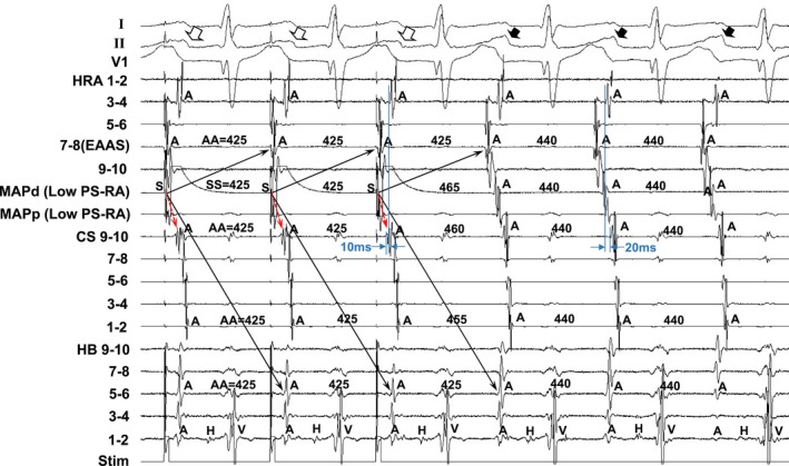
Tracing during manifest entrainment by pacing from the low postero‐septal right atrium (Low PS‐RA) in Patient 7. The ECG leads I, II, and V1 and electrograms recorded from the high right atrium (HRA), coronary sinus (CS), and His bundle (HB) position are shown. d indicates distal; EAAS, indicates earliest atrial activation site; MAP, mapping catheter; p, proximal; Stim, stimulation.
Figure 3 shows the isochronal map during the tachycardia showing the relative locations of the EAAS during the SANRT, the EAAS during sinus rhythm, successful ablation site, and entrainment pacing site (low posteroseptal RA) in patient 7. The EAAS during the tachycardia was observed at the posteroinferior portion of the EAAS during sinus rhythm. The SANRT was terminated by an energy application delivered at a site 12 mm proximal to the EAAS during the SANRT in the direction of the entrainment pacing site. Thus, the successful ablation site (entrance of I‐SANC) was located at the posteroinferior portion of the EAAS during the SANRT.
Figure 3.
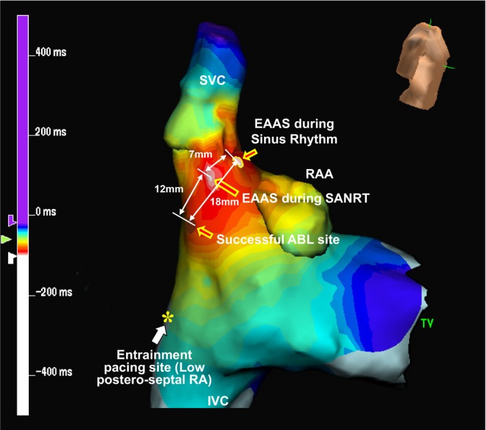
Isochronal map during the SANRT showing the relative locations of the earliest atrial activation site (EAAS) during the SANRT, the EAAS during sinus rhythm, successful ablation (ABL) site, and entrainment pacing site in patient 7. IVC indicates inferior vena cava; RA, right atrium; RAA, right atrial appendage; SANRT, sinoatrial node reentrant tachycardia; SVC, superior vena cava; TV, tricuspid valve.
Figure 4 shows the tracing during a radiofrequency energy application delivered at a site 12 mm proximal to the EAAS (successful ablation site) in patient 7. The atrial electrogram of the successful ablation site appeared 15 ms later than that of HRA 7 to 8 during the SANRT, and the unipolar electrogram exhibited an rS morphology (Figure 4A). However, the SANRT terminated immediately after onset of radiofrequency energy delivery (1.6 seconds; Figure 4B), which suggested that the radiofrequency energy application site was located at the entrance of the I‐SANC.
Figure 4.
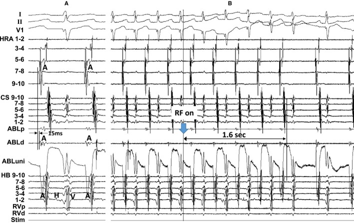
A, The atrial electrogram at the successful ablation (ABL) site (a site 12 mm proximal to the earliest atrial activation site), and (B) shows the tracing during a radiofrequency energy (RF) application delivered to this site in patient 7. The ECG leads I, II, and V1 and electrograms recorded from the high right atrium (HRA), coronary sinus (CS), His bundle (HB) position, and right ventricle (RV) are shown. d indicates distal; p, proximal; Stim, stimulation; uni, unipolar electrogram.
Figure 5 shows the tracing during manifest entrainment in patient 13. The atrial electrogram at the EAAS during the SANRT preceded that at HRA 7 to 8 by 10 ms. During pacing from the distal CS (CS 1–2), the EAAS and HRA recording sites were orthodromically captured by a long conduction interval (solid arrows). All of the electrograms at the EAAS and HRA recording sites exhibited morphologies identical to those during the tachycardia, and the cycle lengths of those electrograms at the orthodromically captured sites were all 490 ms, identical to the pacing interval and shorter than the tachycardia cycle length (510 ms). On the other hand, the atrial electrograms at CS 5 to 6 were captured antidromically during pacing (dashed red arrows). The atrial electrograms at CS 5 to 6 occurred 25 ms later than those at HRA 7 to 8 during pacing, but they were observed 60 ms later during the tachycardia. Furthermore, the electrogram morphologies at CS 5 to 6 during pacing differed from those during the SANRT and the interval of the atrial electrogram at CS 5 to 6 just after pacing (535 ms) was longer than the pacing cycle length (490 ms), indicating the antidromic capture of the electrogram at CS 5 to 6 (dashed red arrows). In addition, the surface P‐wave morphologies in lead II during pacing (open arrows) differed from those during the tachycardia (closed arrows), indicating fusion of the surface P waves during pacing except for the last captured beat.
Figure 5.
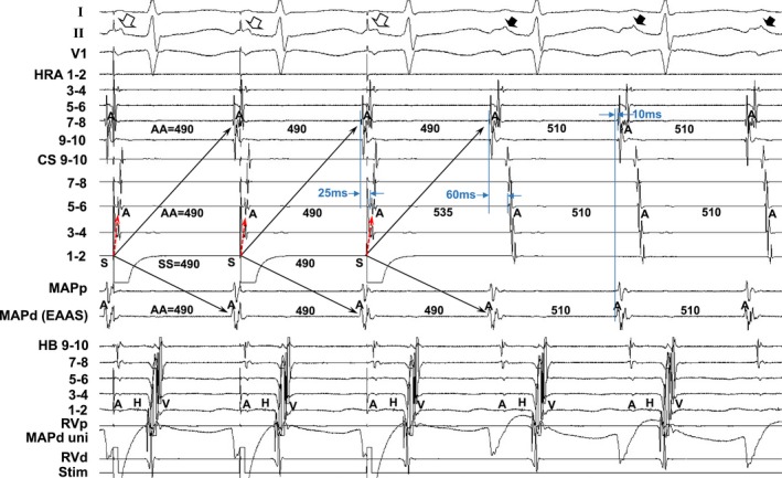
Tracing during manifest entrainment by pacing from the distal coronary sinus (CS 1–2) in patient 13. The ECG leads I, II, and V1 and electrograms recorded from the high right atrium (HRA), coronary sinus (CS), mapping catheter (MAP), His bundle (HB) position, and right ventricle (RV) are shown. d indicates distal; EAAS, earliest atrial activation site; p, proximal; Stim, stimulation; uni, unipolar electrogram.
Figure 6 shows the isochronal map during the tachycardia showing the relative locations of the EAAS during the SANRT, the EAAS during sinus rhythm, successful ablation site, and entrainment pacing site in patient 13. The EAAS during the SANRT was observed at the superior portion of the EAAS during sinus rhythm. The SANRT was terminated by a radiofrequency energy application delivered at a site 9 mm proximal to the EAAS in the direction of the entrainment pacing site (CS 1–2). Thus, the successful ablation site (entrance of I‐SANC) was located at the posterior portion of the EAAS during the SANRT.
Figure 6.
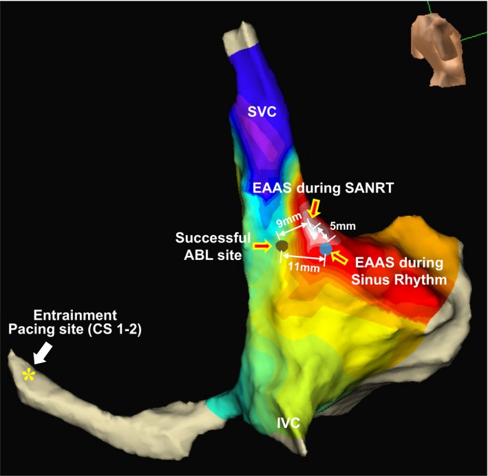
Isochronal map during the tachycardia showing the relative locations of the earliest atrial activation site (EAAS) during the tachycardia, the EAAS during sinus rhythm, successful ablation (ABL) site, and entrainment pacing site (CS 1–2) in patient 13. CS indicates coronary sinus; IVC, inferior vena cava; SANRT, sinoatrial node reentrant tachycardia; SVC, superior vena cava.
Figure 7 summarizes the locations of the EAAS during the SANRT, successful ablation sites, and the pacing sites from which manifest entrainment was demonstrated (entrainment pacing site). The SANRT was successfully terminated by an energy delivery to a site proximal to the EAAS in the direction of the pacing site from where the manifest entrainment was demonstrated. The successful ablation site (entrance of I‐SANC) was observed at the posterior (n=9), posteroinferior (n=4), and inferior (n=2) portions of the EAAS during the SANRT (exit of I‐SANC; Figure 7).
Figure 7.
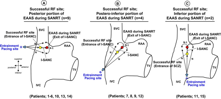
Right anterior oblique views of the right atrium showing the location of the earliest atrial activation site (EAAS) and successful radiofrequency ablation (RF) site. *Entrainment pacing site. I‐SANC indicates intranodal sinoatrial conduction; IVC, inferior vena cava; RAA, right atrial appendage; SANRT, sinoatrial node reentrant tachycardia; SVC, superior vena cava; TV, tricuspid valve.
Anatomical Location of the SANRT Reentry Circuit
The atrial electrogram at the successful ablation site was observed significantly later than that at the EAAS during the SANRT (14.5±3.4 versus 0±0 ms; P<0.0001; Figure 8A). The distance between the EAAS during sinus rhythm and successful ablation site was significantly longer than that between the EAAS during sinus rhythm and EAAS during the SANRT (12.8±4.5 versus 7.2±3.1 mm; P<0.0001; Figure 8B). That indicated that the successful ablation site (entrance of I‐SANC) was located further from the EAAS during sinus rhythm than the EAAS during the SANRT (exit of I‐SANC).
Figure 8.
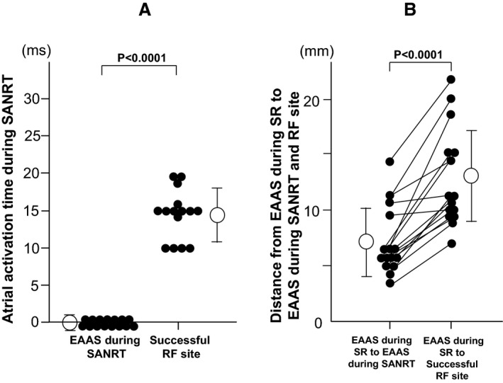
A, The activation time at the earliest atrial activation site (EAAS) during the tachycardia and successful radiofrequency ablation site (RF site) during sinoatrial node reentrant tachycardia (SANRT). B, The distances between the EAAS during sinus rhythm (SR) and the EAAS during SANRT and between the EAAS during SR and successful RF site.
Discussion
This study revealed several new, important findings. First, we demonstrated manifest entrainment during the SANRT and, to the best of our knowledge, showed the precise anatomical reentrant tachycardia circuit for the first time in humans. Second, the SANRT could be terminated by a radiofrequency energy application delivered to the entrance of the reentry circuit, distant from the exit of the circuit, under navigation by manifest entrainment. Third, it was suggested that the reentry circuit involved the perinodal atrium according to the findings of manifest entrainment and the results of the catheter ablation.
Tachycardia Circuit of the SANRT
In the present study, manifest entrainment associated with fusion of the surface P wave was demonstrated and the EAAS was orthodromically captured during entrainment in all patients. Orthodromic capture of the EAAS during manifest entrainment implies that there is an area of slow conduction within the reentry circuit between the entrance and exit sites.6, 7, 8, 10, 11 For fusion of surface P waves to occur, the tachycardia (ie, orthodromic) and stimulated (ie, antidromic) wavefronts must collide with each other in the atria after the tachycardia wavefront exits the I‐SANC6, 7, 8, 10, 11 (Figure 1). This requires the stimulated wavefront to have access to an entrance site of the reentry circuit that is anatomically distinct from the exit site.6, 7, 8, 13 Therefore, fusion of the surface P waves with orthodromic capture of the EAAS during manifest entrainment suggested the presence of an entrance of the I‐SANC distinct from the exit of the I‐SANC (EAAS during SANRT). Satoh et al showed orthodromic capture of the earliest atrial electrogram at the His bundle site by rapid pacing delivered from the coronary sinus during atrioventricular nodal reentrant tachycardia.14 They clearly demonstrated that orthodromic capture of the EAAS implies the presence of an entrance and an exit to the atrium located at distinctly different locations.14 In the present study, SANRT was successfully terminated by an energy delivery to a site proximal to the EAAS in the direction of the pacing site from where the manifest entrainment was demonstrated. These successful ablation sites were located 10.4±2.8 mm away from the EAAS during the SANRT, which was consistent with the previous findings of manifest entrainment.6, 7, 8, 10, 11, 12, 13, 14
Recent optical mapping of explanted human and canine hearts revealed that the sinoatrial node complex has at least 4 preferential sinoatrial conduction pathways, which are responsible for the transmission of electrical impulses to the atrial myocardium.15, 16 These include the superior, lateral, inferior, and septal sinoatrial conduction pathways.15, 16 The atrial breakthrough site is approximately 7.5 mm away from the leading pacemaker in the human sinoatrial node,17 but the distance between the sinoatrial node leading pacemaker and atrial breakthrough sites could vary from 3 to 25 mm because of multiple sinoatrial conduction pathways.15, 16 It has been shown that these sinoatrial conduction pathways have different conduction properties and could lead to beat‐to‐beat variations in the atrial activation.15, 16 In the present study, the EAAS during sinus rhythm slightly differed from that during SANRT. The difference in heart rate between sinus rhythm and SANRT might have resulted in a shift in the exit of the sinoatrial conduction pathways. Glukhov et al examined the sinoatrial node reentry circuit in a canine model using high‐resolution optical mapping and showed both a sinoatrial macro‐reentry (slow‐fast form) involving the atrial myocardium and a micro‐reentry confined within the sinoatrial node.4 In the macro‐reentry circuit, the reentrant wave could propagate into the sinoatrial node through an active sinoatrial conduction pathway and re‐excite the atrial myocardium through an another active sinoatrial conduction pathway, forming a macro‐reentry circuit with 2 main pathways: a slow path (6–8 mm) inside the sinoatrial node and a fast pathway (10–20 mm) located outside of the sinoatrial node.4 These findings are consistent with the findings of the present study that the entrance site was distinct from the exit of the I‐SANC. These multiple active sinoatrial conduction pathways may form the macro‐reentry circuit involving the atrial myocardium as shown in the canine model.4
Catheter Ablation of SANRT
Catheter ablation of SANRT has been conducted targeting the EAAS during tachycardia.9, 18, 19 Kay et al reported that SANRT was terminated promptly upon targeting the EAAS; however, tachycardia could be reinduced in 2 of 4 patients and was associated with a slight shift in the EAAS.18 In those 2 patients, the EAAS shifted 2 to 3 mm laterally after the initial application of radiofrequency current. Therefore, successful ablation of the focus of the SANRT required the application of radiofrequency current within an arc spanning 3 to 5 mm in the region of the sinus node. Thus, they indicated that reentry occurs within the sinus node, sinoatrial atrial myocardium, or a combination of these regions with different exit sites into the surrounding atrial myocardium.18 Goya et al reported that ablation of SANRT targeting the EAAS was successful in all patients.19 However, the tachycardia was still inducible after the SANRT was terminated once by a radiofrequency energy delivery in 6 of 11 patients, associated with a shift in the EAAS from approximately 2 to 7 mm (mean, 4.3) laterally and inferiorly from the initial site of the current application.19 Therefore, they indicated that successful ablation of SANRT requires an energy application over a considerably large area, extending 2 to 7 mm in the region of the sinus node.19 Those previous findings18, 19 indicated that the SANRT circuit can be changed accompanied by a shift in the exit sites, suggesting the presence of multiple sinoatrial conduction pathways,wWhereas in the present study neither reinduction nor a change in location of the EAAS during the SANRT were observed in any of the patients after the successful ablation of the SANRT. Thus, radiofrequency energy delivery to the entrance site of the reentry circuit might be more effective in preventing the occurrence of different SANRTs accompanied by a shift in the EAAS than targeting the exit of the reentry circuit.
It has been reported that a radiofrequency energy delivery to the sinus node region can produce sinus node dysfunction requiring a pacemaker implantation.20 In the present study, the EAAS during the SANRT was observed in the vicinity of the EAAS during sinus rhythm. However, the successful ablation site (entrance of the I‐SANC) was located further from the EAAS during sinus rhythm than the EAAS during the SANRT. Therefore, application of radiofrequency energy to the entrance of the I‐SANC may be an alternative and safer therapeutic option than targeting the EAAS during SANRT.
Study Limitations
Previous reports demonstrated a shift in the leading pacemaker and preferential sinoatrial conduction pathways in human hearts after exposure to adenosine or isoproterenol.4, 21 Therefore, additional functional sinoatrial conduction pathways might be found if we compare the activation sequences between those with and without the administration of isoproterenol and adenosine triphosphate.
Although we regarded the last radiofrequency energy application site at where the tachycardia was terminated as the successful site, there was a possibility that the successful elimination of tachycardia occurred as a cumulative effect of the previous unsuccessful ablation lesions. Also, the successful ablation site might not be just at the entrance site, given that the successful ablation site was identified only by the findings from entrainment. It is possible that the successful ablation site was slightly different from the entrance of the SANRT circuit.
It may be possible that multiple locations can show manifest entrainment in cases in which multiple entrance sites contribute to the reentry circuit. In such cases, multiple radiofrequency energy deliveries to each entrance site may be necessary to terminate the tachycardia.
Although we used only a quadripolar catheter for mapping with the EnSite NavX system, the use of a high‐density mapping catheter might have delineated the reentry circuit more precisely.
Conclusions
The reentry circuit of the SANRT was composed of the entrance and exit of the I‐SANC located at distinctly different anatomical sites. A radiofrequency energy application to the entrance of the I‐SANC, which was identified under navigation with entrainment, can eliminate the SANRT. The entrance of the I‐SANC was located further from the EAAS during sinus rhythm than the exit site, suggesting that an entrance site ablation may be an alternative and safer therapeutic option than targeting the EAAS during SANRT to avoid sinus node dysfunction.
Disclosures
None.
(J Am Heart Assoc. 2020;9:e014472 DOI: 10.1161/JAHA.119.014472.)
References
- 1. Barker PS, Wilson FN, Johnston FD. The mechanism of auricular paroxysmal tachycardia. Am Heart J. 1943;26:435–445. [Google Scholar]
- 2. Han J, Malozzi AM, Moe GK. Sino‐atrial reciprocation in the isolated rabbit heart. Circ Res. 1968;22:355–362. [DOI] [PubMed] [Google Scholar]
- 3. Allessie MA, Bonke FIM. Direct demonstration of sinus node reentry in the rabbit heart. Circ Res. 1979;44:557–568. [DOI] [PubMed] [Google Scholar]
- 4. Glukhov AV, Hage LT, Hansen BJ, Pedraza‐Toscano A, Vargas‐Pinto P, Hamlin RL, Weiss R, Carnes CA, Billman GE, Fedorov VV. Sinoatrial node reentry in a canine chronic left ventricular infarct model: role of intranodal fibrosis and heterogeneity of refractoriness. Circ Arrhythm Electrophysiol. 2013;6:984–994. [DOI] [PMC free article] [PubMed] [Google Scholar]
- 5. Narula OS. Sinus node re‐entry. A mechanism for supraventricular tachycardia. Circulation. 1974;50:1114–1128. [DOI] [PubMed] [Google Scholar]
- 6. Yamabe H, Okumura K, Morihisa K, Koyama J, Kanazawa H, Hoshiyama T, Ogawa H. Demonstration of anatomical reentrant tachycardia circuit in verapamil‐sensitive atrial tachycardia originating from the vicinity of the atrioventricular node. Heart Rhythm. 2012;9:1475–1483. [DOI] [PubMed] [Google Scholar]
- 7. Yamabe H, Okumura K, Koyama J, Kanazawa H, Hoshiyama T, Ogawa H. Demonstration of anatomic reentrant circuit in verapamil‐sensitive atrial tachycardia originating from the atrioventricular annulus other than the vicinity of the atrioventricular node. Am J Cardiol. 2014;113:1822–1828. [DOI] [PubMed] [Google Scholar]
- 8. Yamabe H, Kanazawa H, Ito M, Kaneko S, Kanemaru Y, Kiyama T, Tsujita K. Slow potential at the entrance of the slow conduction zone in the reentry circuit of a verapamil‐sensitive atrial tachycardia originating from the atrioventricular annulus. J Am Heart Assoc. 2018;7:e009223 DOI: 10.1161/JAHA.118.009223. [DOI] [PMC free article] [PubMed] [Google Scholar]
- 9. Sanders WE Jr, Sorrentino RA, Greenfield RA, Shenasa H, Hamer ME, Wharton JM. Catheter ablation of sinoatrial node reentrant tachycardia. J Am Coll Cardiol. 1994;23:926–934. [DOI] [PubMed] [Google Scholar]
- 10. Okumura K, Henthorn RW, Epstein AE, Plumb VJ, Waldo AL. Further observations on transient entrainment: importance of pacing site and properties of the components of the reentry circuit. Circulation. 1985;72:1293–1307. [DOI] [PubMed] [Google Scholar]
- 11. Mann DE, Lawrie GM, Luck JC, Griffin JC, Magro SA, Wyndhan CRC. Importance of pacing site in entrainment of ventricular tachycardia. J Am Coll Cardiol. 1985;5:781–787. [DOI] [PubMed] [Google Scholar]
- 12. Waldo AL, Plumb VJ, Arciniegas JG, MacLean WA, Cooper TB, Priest MF, James TN. Transient entrainment and interruption of the atrioventricular bypass pathway type of paroxysmal atrial tachycardia. A model for understanding and identifying reentrant arrhythmias. Circulation. 1983;67:73–83. [DOI] [PubMed] [Google Scholar]
- 13. Rosenthal ME, Stamato NJ, Almendral JM, Gottlieb CD, Josephson ME. Resetting of ventricular tachycardia with electrocardiographic fusion: incidence and significance. Circulation. 1988;77:581–588. [DOI] [PubMed] [Google Scholar]
- 14. Satoh M, Miyajima S, Koyama S, Ishiguro J, Okabe M. Orthodromic capture of the atrial electrogram during transient entrainment of atrioventricular nodal reentrant tachycardia. Circulation. 1993;88:2329–2336. [DOI] [PubMed] [Google Scholar]
- 15. Fedorov VV, Glukhov AV, Chang R, Kostecki G, Aferol H, Hucker WJ, Wuskell JP, Loew LM, Schuessler RB, Moazami N, Efimov IR. Optical mapping of the isolated coronary‐perfused human sinus node. J Am Coll Cardiol. 2010;56:1386–1394. [DOI] [PMC free article] [PubMed] [Google Scholar]
- 16. Hansen BJ, Csepe TA, Fedorov VV. Mechanisms of normal and dysfunctional sinoatrial nodal excitability and propagation In: Zipes DP, Jalife J, Stevenson WG, eds. Cardiac Electrophysiology: From Cell to Bedside, 7th ed Amsterdam: Elsevier; 2018:259–271. [Google Scholar]
- 17. Csepe TA, Zhao J, Hansen BJ, Li N, Sul LV, Lim P, Wang Y, Simonetti OP, Kilic A, Mohler PJ, Janssen PM, Fedorov VV. Human sinoatrial node structure: 3D microanatomy of sinoatrial conduction pathways. Prog Biophys Mol Biol. 2016;120:164–178. [DOI] [PMC free article] [PubMed] [Google Scholar]
- 18. Kay GN, Chong F, Epstein AE, Dailey SM, Plumb VJ. Radiofrequency ablation for treatment of primary atrial tachycardias. J Am Coll Cardiol. 1993;21:901–909. [DOI] [PubMed] [Google Scholar]
- 19. Goya M, Iesaka Y, Takahashi A, Mitsuhashi T, Yamane T, Soejima Y, Okamoto Y, Gotoh M, Tanaka K, Nitta J, Nogami A, Amemiya H, Aonuma K, Fujiwara H, Hiroe M, Marumo F. Radiofrequency catheter ablation for sinoatrial node reentrant tachycardia: electrophysiologic features of ablation sites. Jpn Circ J. 1999;63:177–183. [DOI] [PubMed] [Google Scholar]
- 20. Rodríguez‐Mañero M, Kreidieh B, Al Rifai M, Ibarra‐Cortez S, Schurmann P, Álvarez PA, Fernández‐López XA, García‐Seara J, Martínez‐Sande L, González‐Juanatey JR, Valderrábano M. Ablation of inappropriate sinus tachycardia: a systematic review of the literature. JACC Clin Electrophysiol. 2017;3:253–265. [DOI] [PMC free article] [PubMed] [Google Scholar]
- 21. Li N, Hansen BJ, Csepe TA, Zhao J, Ignozzi AJ, Sul LV, Zakharkin SO, Kalyanasundaram A, Davis JP, Biesiadecki BJ, Kilic A, Janssen PML, Mohler PJ, Weiss R, Hummel JD, Fedorov VV. Redundant and diverse intranodal pacemakers and conduction pathways protect the human sinoatrial node from failure. Sci Transl Med. 2017;9:eaam5607. [DOI] [PMC free article] [PubMed] [Google Scholar]


