Abstract
Small-angle X-ray scattering (SAXS) is an effective method to obtain microstructural information of materials. However, due to the influence of crystal surface effects, SAXS has a deviation in the characterization of the crystal microstructure. In order to solve the influence of crystal surface effect on the internal defect signal, the microstructure of Octahydro-1,3,5,7-tetranitro-1,3,5,7-tetrazocine (HMX) crystal was characterized by soaking the sample in the matching solution. We found that the absolute scattering intensity, specific surface and volume fraction of the sample in the matching solution are significantly lower than the initial sample, which solves the influence of the crystal surface effect on the test results. Comparing the scattering results of the samples in different electron density matching solutions, it was found that the best result was obtained when using GPL-107 perfluoropolyether (PFPE) matching solution and the same law was obtained by controlling the experiment with 2,4,6,8,10,12-hexanitrohexaazaisowurtzitane (CL-20) crystal. The fitting density was calculated according to the theoretical density and void volume fraction of the sample, and the calculated results are close to the test results of Particle Density Distribution Analyzer (PDDA). Based on this paper, we provide a method to obtain the correct information of crystal microstructure.
Keywords: SAXS, fitting, crystal powder, matching solution
1. Introduction
With the continuous requirements of industry and academia, many advanced materials with excellent properties have been developed and applied in production practice gradually [1,2,3]. It is well known that the ingenious chemical composition and structure determines their incredible application potential. However, various inevitable defects (i.e., point defects, line defects, surface defects) generated in industrial process usually decrease their practical performances such as mechanical properties, resistivity, corrosion resistance, solid-phase transformation, and other physical and chemical properties. Obviously, the density of microscopic defects is becoming one of the most important parameters to evaluate the quality of materials. Accurate microstructure information of materials is significant for evaluating their comprehensive properties and engineering applications.
Traditionally, scanning electron microscope (SEM) and transmission electron microscope (TEM) were used to characterize the microstructure of materials. SEM is designed for directly studying the surfaces of solid objects. It utilizes a beam of focused electrons of relatively low energy as an electron probe that is scanned in a regular manner over the specimen. It can be used to observe particles at a much higher magnification and resolution than can be achieved with a light microscope because the wavelength of an electron is much shorter than that of a photon. Its resolution can reach nanometer level when the conductive material is excited at high voltage. Similarly, TEM is a technique used to observe the features of very small specimens. It used an accelerated beam of electrons, which passes through a very thin specimen to enable a scientist to observe features such as structure and morphology. It also provides higher resolution images than SEM. Using TEM, scientists can be used to view specimens to the atomic level, which is less than 1 nm. Nevertheless, electrons with high energy usually damage some soft materials, and the analysis results cannot reflect their original structure. Of late years, small-angle X-ray scattering (SAXS) technology has gradually attracted people’s attention due to its advantages of good statistics, simple sample preparation and non-destructive testing. Based on the coherent scattering near the incident beam (usually 0.05°–5°), it is extremely sensitive to the scattering length density variation of several nanometers to several hundred nanometers. It is becoming the ideal candidate to supplement the technique of SEM and TEM. At present, SAXS has been widely used as an advanced means for obtaining specific information on the number and size distribution of internal defects of materials, such as polymer materials [4,5,6,7,8,9], nanocomposites [10,11,12] and energetic materials [13,14,15,16,17,18,19,20,21]. However, it is still very challenging for characterizing the crystal powder accuracy by SAXS. On the one hand, the absolute scattering intensity should be corrected. On the other hand, because the surface effect of crystal affects the scattered signal, the test results cannot reflect the real structure inside the crystal.
In the field of energetic materials, the hot spots [22,23,24] caused by microscopic defects in explosive crystals usually lead to negative effects on the properties, such as improved shock wave sensitivity [25], decreased mechanical properties [26,27] and thermal stability [28]. In this work, in order to characterize the quality of explosive crystals, SAXS technology was employed. To remove interference from the cracks and voids between particles, some match solutions with different electron densities (i.e., cyclohexane, polydimethylsiloxane and GPL-107 perfluoropolyether) was used to infiltrate the crystal powders of CL-20 and HMX. It was found that the SAXS results were accurate when the electron density of the matching solution was close to that of the sample. Further, the real scattering data of the inner structure of the explosive crystal were obtained by correcting the absolute scattering intensity of the sample and comparing the change of the specific surface and volume fraction of the voids.
2. Results and Discussion
2.1. Research on Microstructure of HMX
In small-angle X-ray scattering technique, the measured scattering intensity of sample is only relative intensity, which is related to experimental conditions and sample size (such as thickness). Absolute intensity is the ratio of scattered light intensity to incident ray intensity, also known as unit volume differential scattering cross section, which is similar to Rayleigh ratio in light scattering. It is only related to the nature of the sample itself, and has nothing to do with the external conditions such as test instrument, exposure time and sample size. Absolute scattering intensity is used to calculate parameters related to mass density, such as relative molecular mass [29,30] and electron density difference [31]. Absolute intensity is also called unit volume differential scattering cross section. The differential scattering cross section is defined [32] as the ratio of optical intensity scattered per unit time unit solid angle to incident light intensity. Based on the above definition, we can obtain the relationship between the absolute scattering intensity and the measured relative intensity:
| (1) |
where dΣ/dΩ is the absolute scattering intensity; Is is the relative scattering intensity of the sample; Ibg is the relative scattering intensity of the background; Ts and Tbg are the transmittance of the sample and the background, respectively; I0 is the incident ray intensity (counts s−1); d is the thickness of the sample; t is the exposure time; P1 and P2 are the sizes of the pixel in the horizontal and vertical directions; L0 is the distance from the sample to the detector; LP is the distance of the sample to a pixel. The structural parameters of the scattering system can be accurately calculated from the corrected absolute scattering intensity. Therefore, absolute scattering intensity correction is essential.
Figure S1 shows the selected SAXS patterns of HMX samples in different matching solutions. Since all samples are tested under the same conditions, the range of scattering vector q (q = 4πsinθ/λ, where 2θ is the scattering angle and λ is the wavelength of the X-ray) is the same. The scattering invariant Q is defined as follows:
| (2) |
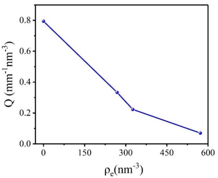
It can be known that the scattering invariant Q is consistent with the change law of the absolute scattering intensity. The calculation results of the scattering invariant Q in different electron density matching solution of HMX crystal are shown in Figure 1. The results showed that the absolute scattering intensity of the HMX crystal which is not infiltrated by the matching solution is highest. It proves that apart from the voids in HMX crystal itself, the crystal surface effect also affects the scattering results. From the principle of SAXS technology, it can be recognized that the scattered signal of the sample comes from the difference in electron density between the two phases. The electron density can be obtained according to:
| (3) |
where E is the atomic number; M is the molar mass; ρm is the mass density. Absolute scattering intensity is significantly reduced when HMX crystals are infiltrated into the matching solution. With the constant change of electron density of matching solution, the absolute scattering intensity also changed gradually. It is showed that in addition to the scattering signal of the internal voids of the crystal, the difference of electron density between the matching solution and the crystal also contributes to the scattering signal. The theoretical density of β-HMX at 20 °C is about 1.902 g/cm3, and the corresponding electron density is 588.170 nm−3. It was found that the absolute scattering intensity was the weakest when the electron density of the matched solution was 571.727 nm−3. It is proved that the smaller the difference of electron density between the matching solution and sample, the smaller contribution to the scattering signal. Therefore, the scattering signal of HMX crystal is relatively accurate only in the PFPE matching solution.
Figure 1.
Scattering invariant Q of HMX crystal in different electron density matching solutions.
In addition, we also studied the volume fraction and specific surface of the voids in HMX. The volume fraction of voids can be obtained according to:
| (4) |
where φA and φB denote the volume fraction of the sample and the voids, and ρA and ρB are the corresponding electron density, respectively. Ie is the scattering intensity of an electron:
| (5) |
where re is a classical electron radius with a size of 2.818 × 10⁻¹³ cm. The polarization factor is approximately 1 in the small angle region. According to Porod method, the specific surface S/V of the two-phase system can be obtained by the following equation:
| (6) |
where Kp is the Porod constant.
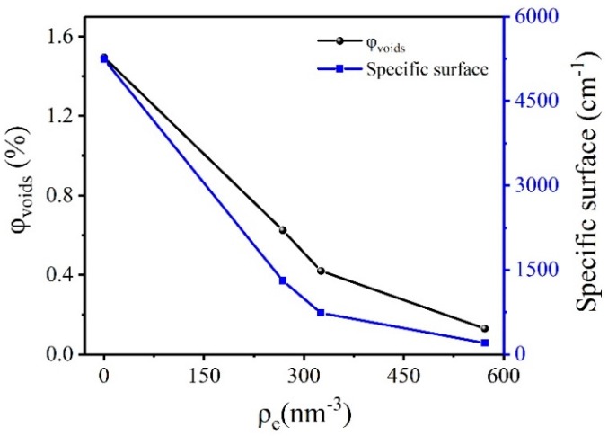
From Equations (4)–(6), we can calculate the specific surface and the volume fraction of the voids in the crystal. The results are shown in Figure 2. When HMX crystal was not infiltrated by matched solution, the volume fraction and specific surface of the voids were the largest, which was 1.495% and 5241.280 cm−1, respectively. With the increase of electron density of the matched solution, the volume fraction and the specific surface of the voids decreased. The results show that the volume fraction and the specific surface of the HMX crystal voids are inaccurate due to the surface effect of the crystal without the addition of a matching solution. The closer electron density between the matching solution and the crystal can be expected to result in smaller the volume fraction and specific surface of the voids. It is indicated that the electron density difference between the matching solution and the sample has an effect on the calculated results. The volume fraction and the specific surface of the voids in the perfluoropolyether matching solution were the smallest, 0.130% and 201.580 cm−1, respectively.
Figure 2.
Volume fraction and specific surface of voids in HMX crystals in different electron density matching solutions.
According to Equations (2) and (4), the calculation result of void volume fraction is related to the scattering invariant Q, and the scattering invariant Q is related to the absolute scattering intensity of the sample. Since it is difficult to find a matching solution with the same electron density as the HMX crystal, the absolute scattering intensity results obtained are often affected by the difference in electron density between the HMX crystal and the matching solution. In order to obtain the true volume fraction of the crystal voids, we studied the influence of the electron density difference between the HMX crystal and the matching solution on the scattering signal. Equations (7)–(9) is transformed from Equation (4).
| (7) |
| (8) |
| (9) |
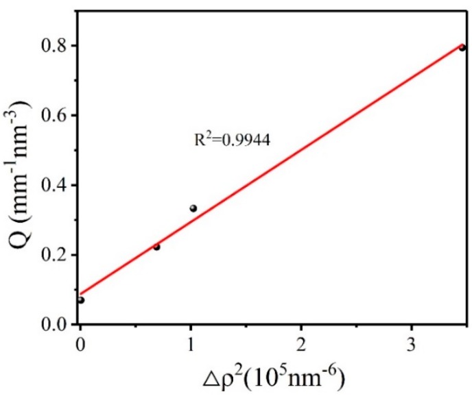
where ρ3 and φ3 are the electron density and volume fraction of the matching solution; φ1 and φ2 denote the volume fraction of HMX crystals and the voids, and ρ1 and ρ2 are the corresponding electron density, respectively. Scattering invariant Q1 depends on the absolute scattering intensity of the voids inside the HMX explosive crystal. Since the voids inside the crystal depend on the nature of the sample itself, we assume that Q1 is a constant b. The scattering invariant Q2 depends on the scattered signal caused by the difference in electron density between the HMX crystal and matching solution, which we assume is aΔρ2. Therefore, we transform the obtained scattering invariant Q into a linear regression equation. Figure 3 shows the scattering invariant Q for HMX crystal varies with the square of the electron density difference:
Figure 3.
Scattering invariant Q for HMX crystal as a function of electron density difference.
As can be seen, linear fitting of the data has a good result. The results show that the scattering constant Q is proportional to the square of the electron density difference between the HMX crystal and the matching solution. The larger the electron density difference is, the greater the influence on the scattering signal of the crystal will be. The true volume fraction of the voids in HMX crystal calculated by intercept b is 0.130%. The fitting density of HMX crystal is calculated according to Equations (10)–(14):
| (10) |
| (11) |
where ρm,1, V1, and m1 represent the theoretical density, volume, and mass of the HMX crystal, respectively; ρm,2, V2, and m2 are the density, volume, and mass of the voids, respectively. Since the voids mass and density are both zero, Equations (10) and (11) can be converted to:
| (12) |
| (13) |
| (14) |
where ρm,3 is the true mass density of the HMX crystal. We calculated that the fitting density of the HMX is 1.8995 g/cm3. The PDDA was used to test the HMX crystal and the true density was 1.8993 g/cm3, which was consistent with the fitting density. Figure S2 shows the mass density distribution of HMX crystal. By using the void volume fraction of the HMX crystal that was not infiltrated by the matching solution, the calculated density was 1.8736 g/cm3, which was smaller than the true density of the sample. Obviously, the result is incorrect. The results of HMX are shown in Table 1.
Table 1.
Calculation results of parameters of 1,3,5,7-tetranitro-1,3,5,7-tetrazacyclooctane (HMX) crystal under different conditions.
| Sample | Parameter | Untreat | Cyclohexane | Polydimethylsiloxane | Pfpe |
|---|---|---|---|---|---|
| Q (mm−1 nm−3) | 0.794 | 0.333 | 0.223 | 0.07 | |
| Void volume fraction | 1.495% | 0.625% | 0.420% | 0.130% | |
| HMX | Specific surface (cm−1) |
5241.280 | 1308.420 | 736.830 | 201.580 |
|
ρm,c (g/cm3) |
1.8736 | 1.8901 | 1.8940 | 1.8995 | |
|
ρm,t (g/cm3) |
1.8993 | ||||
ρm,c is the mass density of the sample in the air and different matching solution; ρm,t is the true mass density obtained by PDDA; ρm,c and ρm,t have the same meaning in all the tables in the article.
2.2. Research on Microstructure of CL-20 Crystal with Low Quality
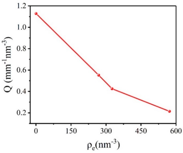
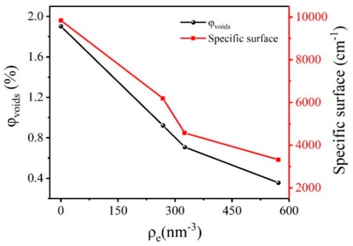
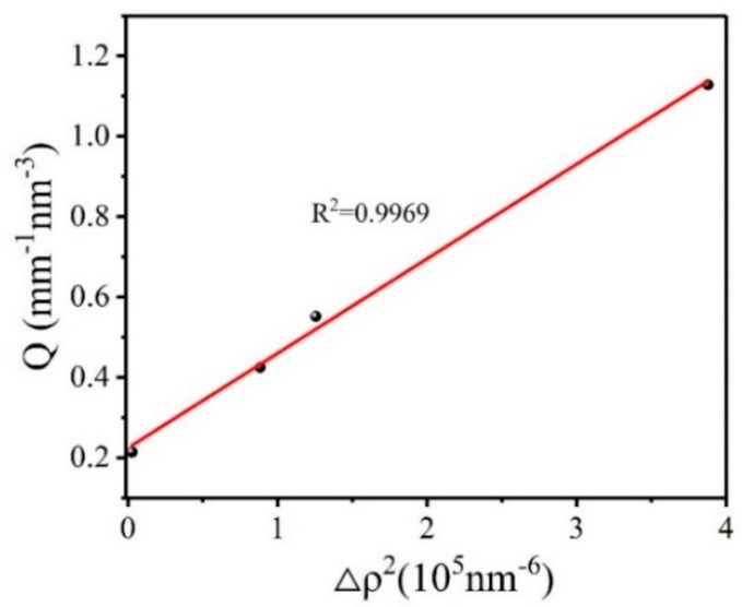
In order to verify the applicability of the method, we selected CL-20-1 crystal for comparative experiments. Figure S3 shows the selected SAXS patterns of CL-20-1 samples in different matching solutions. Figure 4 shows the calculation results of the scattering invariant Q in different electron density matching solution of CL-20-1 crystal. It can be seen that the absolute scattering intensity of CL-20-1 crystal in the matching solution is significantly reduced. The theoretical density of ε-CL-20 at 20 °C is about 2.040 g/cm3, and the corresponding electron density is 622.658 nm−3. We found that the closer the electron density of the matching solution and the CL-20-1 crystal is, the lower the absolute scattering intensity will be. The calculation results of specific surface and the volume fraction of CL-20-1 crystal voids are shown in Figure 5. It can be found that the specific surface and volume fraction of the voids were the maximum when the CL-20-1 crystal was not infiltrated by the matched solution, which was 1.903% and 9840.020 cm−1, respectively. The closer electron density of the matching solution and CL-20-1 crystal can result in the smaller volume fraction and the specific surface of the voids. The volume fraction and specific surface of the voids in the perfluoropolyether matching solution were the smallest, 0.356% and 3315.550 cm−1, respectively. It can be concluded that with the increase of the electron density of the matching solution, the specific surface and volume fraction of the void in CL-20-1 crystal decrease, which is consistent with the change law of HMX crystal. Figure 6 shows the scattering invariant Q for CL-20-1 crystal varies with the square of the electron density difference:
Figure 4.
Scattering invariant Q of CL-20-1 crystal in different electron density matching solution.
Figure 5.
Volume fraction and specific surface of voids in CL-20-1 crystals in different electron density matching solutions.
Figure 6.
Scattering invariant Q for CL-20-1 crystal as a function of electron density difference.
The results of CL-20-1 are shown in Table 2. As we can see, the data fits linearly with good results. The true volume fraction of the voids in the crystal calculated from the intercept b is 0.405%. The fitting density of CL-20-1 crystal is calculated as 2.0317 g/cm3. The PDDA was used to measure CL-20-1 crystal, and the true density was 2.0080 g/cm3, which was smaller than the fitting density. Figure S4 shows the mass density distribution of CL-20-1. The calculated density is relatively high due to the following two reasons: ①Some large defects in the crystal exceed the detection limit of the instrument, and the relevant SAXS data cannot be obtained. ②CL-20-1 crystal has a certain density difference, the test sample itself density is not uniform. But the HMX test deviation was significantly lower than that of CL-20-1 crystal, which indicated that good quality of crystal was conducive to accurate SAXS test results.
Table 2.
Calculation results of parameters of CL-20-1 crystal under different conditions.
| Sample | Parameter | Untreat | Cyclohexane | Polydimethylsiloxane | Pfpe |
|---|---|---|---|---|---|
|
Q (mm−1 nm−3) |
1.129 | 0.552 | 0.425 | 0.214 | |
| Void volume fraction | 1.903% | 0.922% | 0.708% | 0.356% | |
| CL-20-1 | Specific surface (cm−1) |
9840.020 | 6190.500 | 4568.880 | 3315.550 |
|
ρm,c (g/cm3) |
2.0012 | 2.0212 | 2.0256 | 2.0327 | |
|
ρm,t (g/cm3) |
2.0080 | ||||
2.3. Research on Microstructure of CL-20 with Different Sizes
According to the above results, we selected GPL-107 perfluoropolyether reagent as the matching solution and tested CL-20 crystals of the same quality and different particle size with SAXS technology. Figure S5 shows the selected SAXS patterns of CL-20 samples with different particle sizes in different matching solutions. The GPL-107 perfluoropolyether reagent was selected as the matching solution due to its high electron density and the lower electron density contrast between itself and CL-20 crystal. This enabled us to investigate the voids in crystal using SAXS without too much interference of the scattering from the difference in electron density between the crystal and the matching solution.
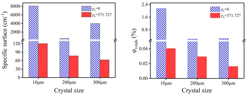
Figure 7 shows the results of the void volume fraction and specific surface of CL-20 crystals with different particle sizes. Since the crystal surface effect will have a significant impact on the SAXS test results, the consequences of the crystal without infiltrating the matching solution have a lot of randomness. After infiltrating in the PFPE matching solution, the volume fraction and the specific surface of the voids in the crystals decreases with the increase of the crystal size. At the same temperature, the theoretical density of CL-20 crystals with different particle sizes is identical. It can be known from Equation (14) that the larger volume fraction of the voids can give rise to the smaller density of the crystals. Therefore, the density of the crystal should decrease as the particle size increase. Table 3 presents the results of CL-20 crystals with different particle sizes. Based on the results calculated in PFPE, we can see that the density of the CL-20-4 is the highest, and the density of the CL-20-2 crystal is the lowest, which is consistent with the regular of true density. The mass density distribution of CL-20-2, CL-20-3, and CL-20-4 are given in Figures S6–S8, respectively. These results confirm our speculation and show that the data are correct. Because the quality of sample is better, the deviation between the calculated density and the true density is small.
Figure 7.
Specific surface (left) and volume fraction (right) of voids in air and perfluoropolyether matching solution of CL-20 crystals with different particle sizes.
Table 3.
Parameter calculation results of CL-20 crystal with different particle size under different conditions.
| Sample | Condition | Void Volume Fraction | Specific Surface(cm−1) | ρm,c (g/cm3) | ρm,t (g/cm3) |
|---|---|---|---|---|---|
| CL-20-2 (10 μm) | Untreat | 2.140% | 8077.501 | 1.9963 | 2.0368 |
| PFPE | 0.0403% | 120.213 | 2.0392 | ||
| CL-20-3 (200 μm) | Untreat | 0.210% | 512.591 | 2.0357 | 2.0371 |
| PFPE | 0.0293% | 76.953 | 2.0394 | ||
| CL-20-4 (300 μm) | Untreat | 0.241% | 3985.635 | 2.0351 | 2.0380 |
| PFPE | 0.0161% | 62.666 | 2.0396 |
3. Experimental
Raw CL-20 and HMX were provided by the Institute of Chemical Materials, Chinese Academy of Engineering Physics (CAEP). Cyclohexane (ρe = 268.409 nm−3) was provided by Sinopharm Chemical Reagent Factory. Polydimethylsiloxane (ρe = 325.514 nm−3) was purchased from Dow corning and GPL-107 perfluoropolyether (ρe = 571.727 nm−3) was purchased from Banliwei information technology co. LTD. CL-20-1 is a kind of explosive crystal with many defects, which is used for methodology research. CL-20-2, CL-20-3 and CL-20-4 are crystals of 10 μm, 200 μm and 300 μm, respectively.
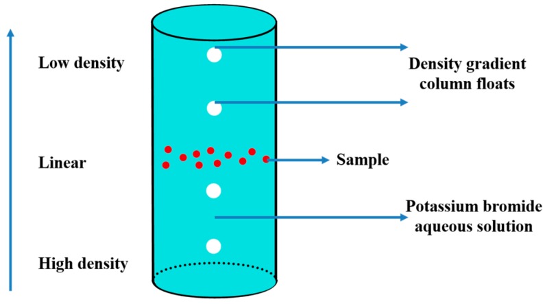
The true density of CL-20 and HMX crystal was taken with density gradient column floats in PDDA-SMART Particle Density Distribution Analyzer (PDDA). The density gradient solution is configured by zinc bromide aqueous solution. Figure 8 shows the principle of PDDA.
Figure 8.
Schematic diagram of PDDA.
The SAXS experiments were conducted with a Xeuss system of Xenocs 2.0, France. The system is equipped with a multilayer focused Cu Kα X-ray source (GeniX3D λ = 0.154 nm), generated at 50 kV and 0.6 mA. Two pairs of scatterless slits were located 1500 mm apart from each other for collimating the X-ray beam. Scattering data were recorded with the aid of a Pilatus 300 K detector (resolution: 487 × 618, pixel size = 172 µm). In order to get a larger size of information, we shifted the Beam stop up slightly. The effective range of the characteristic dimension was 10–400 nm. The sample-to-detector distance was 2490 mm. The collection time for SAXS patterns was set as 600 s after each step. The CL-20 crystal was sufficiently wetted in cyclohexane, polydimethylsiloxane, and GPL-107 perfluoropolyether matching solution, and packaged in an iron piece having a diameter of 2 mm and a height of 1mm using a Kapton Tape. A sample without any treatment was selected for comparison and the CL-20 crystal is treated in the same way as HMX crystal. The X-rays are scattered by the sample and recorded as two-dimensional data by the detector, and processed into a one-dimensional curve by the software Fit-2D. Figures S9–S11 show the 1D SAXS curves of HMX, CL-20-1, and CL-20 with different particle sizes in different matching solutions, respectively.
4. Conclusions
In this paper, the scattering data which can reflect the real structure inside the crystal is obtained by infiltrating the crystal into the matching solution. It was found that the influence of crystal surface effect on the test results can be effectively solved. It is worth noting that the electron density of the matching solution should be the same or similar to the electron density of the sample. By fitting the scattering invariant Q of CL-20 and HMX crystals in different electron density matching solutions, the volume fraction of the voids inside the crystal was obtained. The fitting density of the crystal is close to the test result of PDDA, which proves the effectiveness of the method. As for CL-20 crystals with different particle sizes, SAXS results show that scattering data with small deviation can be obtained in GPL-107 perfluoropolyether matching solution. This method is suitable for SAXS research of crystals with different types and sizes.
Supplementary Materials
The following are available online. Figure S1: Selected SAXS patterns of HMX at room temperature taken at different matching solution as indicated on the graph, Figure S2: Mass density distribution of HMX, Figure S3: Selected SAXS patterns of CL-20-1 at room temperature taken at different matching solution as indicated on the graph, Figure S4: Mass density distribution of CL-20-1, Figure S5: Selected SAXS patterns of CL-20-2, CL-20-3 and CL-20-4 at room temperature taken at different matching solution as indicated on the graph, Figure S6: Mass density distribution of CL-20-2, Figure S7: Mass density distribution of CL-20-3, Figure S8: Mass density distribution of CL-20-4, Figure S9: Representative SAXS curves of the HMX in different matching solutions, Figure S10: Representative SAXS curves of the CL-20-1 in different matching solutions, Figure S11: Representative SAXS curves of CL-20-2, CL-20-3 and CL-20-4 in different matching solutions.
Author Contributions
H.W. conducted all the experiments; H.Z. discussed the experimental results with J.S.; S.S. and J.X. modified the article; Y.L., C.Z., J.L. and S.W. provided instruments and research ideas. All authors have read and agreed to the published version of the manuscript.
Funding
This work is supported by the National Natural Science Foundation of China (No.21805259). Thanks are also due to Yongfeng Men and Ran Chen at Changchun Institute of Applied Chemistry for guidance and help to the experiment.
Conflicts of Interest
The authors declare that they have no conflict of interest.
Footnotes
Sample Availability: Samples of the compounds are not available from the authors.
References
- 1.Chen X., Wang W., Jiao C. A recycled environmental friendly flame retardant by modifying para-aramid fiber with phosphorus acid for thermoplastic polyurethane elastomer. J. Hazard. Mater. 2017;331:257–264. doi: 10.1016/j.jhazmat.2017.02.011. [DOI] [PubMed] [Google Scholar]
- 2.Liu F., Hashim N.A., Liu Y., Abed M.M., Li K. Progress in the production and modification of PVDF membranes. J. Membr. Sci. 2011;375:1–27. doi: 10.1016/j.memsci.2011.03.014. [DOI] [Google Scholar]
- 3.Zhao X., Lang Q., Yildirimer L., Lin Z.Y., Cui W., Annabi N., Ng K.W., Dokmeci M.R., Ghaemmaghami A.M., Khademhosseini A. Photocrosslinkable gelatin hydrogel for epidermal tissue engineering. Adv. Healthcare. Mater. 2016;5:108–118. doi: 10.1002/adhm.201500005. [DOI] [PMC free article] [PubMed] [Google Scholar]
- 4.Fischer S., Diesner T., Rieger B., Marti O. Simulating and evaluating small-angle X-ray scattering of micro-voids in polypropylene during mechanical deformation. J. Appl. Crystallogr. 2010;43:603–610. doi: 10.1107/S0021889810006163. [DOI] [Google Scholar]
- 5.Stoclet G., Lefebvre J.M., Yeniad B., Du Sart G.G., De Vos S. On the strain-induced structural evolution of Poly (ethylene-2, 5-furanoate) upon uniaxial stretching: An in-situ SAXS-WAXS study. Polymer. 2018;134:227–241. doi: 10.1016/j.polymer.2017.11.071. [DOI] [Google Scholar]
- 6.Fischer S., Jiang Z., Men Y. Analysis of the Lamellar Structure of Semicrystalline Polymers by Direct Model Fitting of SAXS Patterns. J. Phys. Chem. B. 2011;115:13803–13808. doi: 10.1021/jp204998p. [DOI] [PubMed] [Google Scholar]
- 7.Chen R., Lu Y., Zhao J., Jiang Z., Men Y. Two-step cavitation in semi-crystalline polymer during stretching at temperature below glass transition. J. Polym. Sci. Part B Polym Phys. 2016;54:2007–2014. doi: 10.1002/polb.24108. [DOI] [Google Scholar]
- 8.Chen R., Lu Y., Jiang Z., Men Y. Cavitation in Poly (4-methyl-1-pentene) during Tensile Deformation. J. Phys. Chem. B. 2018;122:4159–4168. doi: 10.1021/acs.jpcb.8b00060. [DOI] [PubMed] [Google Scholar]
- 9.Xiong B., Lame O., Chenal J.M., Richas C., Seguela R., Vigier G. In-situ SAXS study and modeling of the cavitation/crystal-shear competition in semi-crystalline polymers: Influence of temperature and microstructure in polyethylene. Polymer. 2013;54:5408–5418. doi: 10.1016/j.polymer.2013.07.055. [DOI] [Google Scholar]
- 10.Li J.L., Yin J.H., Ji T., Feng Y., Liu Y.Y., Zhao H., Li Y.P., Zhu C.C., Yue D., Su B. Microstructure evolution effect on high-temperature thermal conductivity of LDPE/BNNS investigated by in-situ SAXS. Mater. Lett. 2019;234:74–78. doi: 10.1016/j.matlet.2018.09.061. [DOI] [Google Scholar]
- 11.Li Y., Yang C., Li N., Yin J., Feng Y., Liu Y.Y., Li J.L., Zhao H., Yue D., Liu X. Microstructure and electrical properties of polyimide-based composites reinforced by high-aspect-ratio titanium oxide nanowires. Surf. Coat. Technol. 2019;361:425–431. doi: 10.1016/j.surfcoat.2019.01.066. [DOI] [Google Scholar]
- 12.Khan I., Mohan S.D., Belbut M., Kamma-Lorger C.S., Mateus A., Mitchell G.R. Multiscale structure evolution in electrically conductive nanocomposites studied by SAXS. Procedia. Manu. 2017;12:79–88. doi: 10.1016/j.promfg.2017.08.011. [DOI] [Google Scholar]
- 13.Tian Q., Yan G., Sun G., Huang C., Xie L., Chen B., Huang M., Liu H., Liu X., Wang J. Thermally induced damage in hexanitrohexaazaisowurtzitane. Cent. Eur J. Energy Mater. 2013;10:359–369. [Google Scholar]
- 14.Mang J.T., Skidmore C.B., Son S.F., Hjelm R.P., Rieker T.P. An Optical Microscopy and Small-Angle Scattering Study of Porosity in Thermally Treated PBX 9501. AIP Conf. Proc. 2002;620:833–836. [Google Scholar]
- 15.Willey T.M., Lauderbach L., Gagliardi F., Van Buuren T., Glascoe E.A., Tringe J.W., Lee R.I., Springer H.K., Ilavsky J. Mesoscale evolution of voids and microstructural changes in HMX-based explosives during heating through the β-δ phase transition. J. Appl. Phys. 2015;118:055901. doi: 10.1063/1.4927614. [DOI] [Google Scholar]
- 16.Peterson P.D., Mang J.T., Asay B.W. Quantitative analysis of damage in an octahydro-1, 3, 5, 7-tetranitro-1, 3, 5, 7-tetrazonic-based composite explosive subjected to a linear thermal gradient. J. Appl. Phys. 2005;97:093507. doi: 10.1063/1.1879072. [DOI] [Google Scholar]
- 17.Yan G.Y., Tian Q., Liu J.H., Fan Z., Sun G., Zhang C., Wang Y., Chen B., Gong J., Zhou X. The Microstructural Evolution in HMX Based Plastic-bonded Explosive During Heating and Cooling Process: An in situ Small-angle Scattering Study. Cent. Eur. J. Energy Mater. 2016;13:916–926. doi: 10.22211/cejem/65826. [DOI] [Google Scholar]
- 18.Yan G.Y., Tian Q., Liu J.H., Chen B., Sun G.A., Huang M., Li X.H. Small-angle X-ray analysis of the effect of grain size on the thermal damage of octahydro-1, 3, 5, 7-tetranitro-1, 3, 5, 7 tetrazocine-based plastic-bounded explosives. Chin. Phys. B. 2014;23:076101. doi: 10.1088/1674-1056/23/7/076101. [DOI] [Google Scholar]
- 19.Smirnov E.B., Muzyrya A.K., Kostitsyn O.V., Badretdinova L.C., Ten K.A., Pruuel E.R., Tolochko B.P., Sharafutdinov M.R., Shmakov A.N., Kuper K.V. Investigation of micro-, meso-, and macrostructure of the condensed heterogeneous explosives using synchrotron radiation. Bull. Russ. Acad. Sci. Phys. 2015;79:20–25. doi: 10.3103/S1062873815010293. [DOI] [Google Scholar]
- 20.Willey T.M., Hoffman D.M., van Buuren T., Lauderbach L., Gee R.H., Maiti A., Overturf G.E., Fried L.E., Ilavsky J. The Microstructure of TATB-Based Explosive Formulations During Temperature Cycling Using Ultra-Small-Angle X-Ray Scattering. Propellants. Explos. Pyrotech. 2009;34:406–414. doi: 10.1002/prep.200800031. [DOI] [Google Scholar]
- 21.Willey T.M., van Buuren T., Lee J.R., Overturf G.E., Kinney J.H., Handly J., Weeks B.L., Ilavsky J. Changes in Pore Size Distribution upon Thermal Cycling of TATB-based Explosives Measured by Ultra-Small Angle X-Ray Scattering. Propellants. Explos. Pyrotech. 2006;31:466–471. doi: 10.1002/prep.200600063. [DOI] [Google Scholar]
- 22.Hsu P., Souers P.C., Chidester S., De Haven M., Garza R., Harwood P., Maienschein J. Detonation Measurements on Damaged LX-04. Propellants. Explos. Pyrotech. 2007;32:509–513. doi: 10.1002/prep.200700206. [DOI] [Google Scholar]
- 23.Urtiew P.A., Tarver C.M. Shock initiation of energetic materials at different initial temperatures. Combust. Explos. Shock. Waves. 2005;41:766–776. doi: 10.1007/s10573-005-0085-0. [DOI] [Google Scholar]
- 24.Bassett W.P., Dlott D.D. Shock initiation of explosives: Temperature spikes and growth spurts. Appl. Phys. Lett. 2016;109:091903. doi: 10.1063/1.4961619. [DOI] [Google Scholar]
- 25.Hua C., Huang M., Huang H., Li J.S., Nie F.D., Dai B. Intragranular Defects and Shock Sensitivity of RDX/HMX. Chin. J. Energy Mater. 2010;18:152–157. [Google Scholar]
- 26.Palmer S.J., Field J.E., Huntley J.M. Deformation, strengths and strains to failure of polymer bonded explosives. Proc. R. Soc. Lond. Ser. A. 1993;440:399–419. doi: 10.1098/rspa.1993.0023. [DOI] [Google Scholar]
- 27.Tan H., Huang Y., Liu C., Geubelle P.H. The Mori–Tanaka method for composite materials with nonlinear interface debonding. Int. J. Plast. 2005;21:1890–1918. doi: 10.1016/j.ijplas.2004.10.001. [DOI] [Google Scholar]
- 28.Sudhakar A.O.R., Mathew S. Thermal behaviour of CuO doped phase-stabilised ammonium nitrate. Thermochim. Acta. 2006;451:5–9. doi: 10.1016/j.tca.2006.08.013. [DOI] [Google Scholar]
- 29.Kratky O., Porod G., Kahovec L. Einige Neuerungen in der Technik und Auswertung von Röntgen-Kleinwinkelmessungen. Z. Elektrochem. 1951;55:53–59. [Google Scholar]
- 30.Orthaber D., Bergmann A., Glatter O. SAXS experiments on absolute scale with Kratky systems using water as a secondary standard. J. Appl. Crystallogr. 2000;33:218–225. doi: 10.1107/S0021889899015216. [DOI] [Google Scholar]
- 31.Lin J.S., Hendricks R.W., Schultz J.M., McCready M.J. Absolute integrated SAXS measurements during the crystallization of linear polyethylene. J. Polym. Sci. Polym. Phys. Ed. 1982;20:1365–1369. doi: 10.1002/pol.1982.180200803. [DOI] [Google Scholar]
- 32.Russell T.P., Lin J.S., Spooner S. Intercalibration of small-angle X-ray and neutron scattering data. J. Appl. Crystallogr. 1988;21:629–638. doi: 10.1107/S0021889888004820. [DOI] [Google Scholar]
Associated Data
This section collects any data citations, data availability statements, or supplementary materials included in this article.


