Abstract
We report the design and experimental demonstration of a frequency tunable terahertz gyrotron at 527 GHz built for an 800 MHz Dynamic Nuclear Polarization enhanced Nuclear Magnetic Resonance (DNP-NMR) spectrometer. The gyrotron is designed at the second harmonic (ω = 2ωc) of the electron cyclotron frequency. It produces up to 9.3 W continuous microwave (CW) power at 527.2 GHz frequency using a diode type electron gun operating at V = 16.65 kV, Ib = 110 mA in a TE11,2,1 mode, corresponding to an efficiency of ~0.5%. The gyrotron is tunable within ~ 0.4 GHz by combining voltage and magnetic field tuning. The gyrotron has an internal mode converter that produces a Gaussian-like beam that couples to the HE11 mode of an internal 12 mm i.d. corrugated waveguide periscope assembly leading up to the output window. An external corrugated waveguide transmission line system is built including a corrugated taper from 12 mm to 16 mm i.d. waveguide followed by 3 m of the 16 mm i.d. waveguide The microwave beam profile is measured using a pyroelectric camera showing ~ 84% HE11 mode content.
Keywords: Terahertz, frequency tunable gyrotron, Dynamic Nuclear Polarization, electron beam, Gaussian beam, Corrugated waveguide
I. Introduction
NUCLEAR Magnetic Resonance spectroscopy at higher magnetic fields has become a unique tool for improving the spectral resolution to non-invasively probe atomic structures of biological macromolecules such as membrane proteins and non-protein molecular assemblies [1–4]. However, the problems associated with the poor polarization in conventional NMR spectroscopy, typically < 0.01%, of the proton nuclei leads to low sensitivity and poor signal. Using microwaves matching the corresponding electron frequencies in the same electron-nuclei system one can dynamically transfer the polarization of unpaired electrons to the protons by redistributing the Boltzmann population of the spin states among the 1H protons, a process called Dynamic Nuclear Polarization or DNP-NMR. This increases the population difference between the nuclei spin-up and spin-down states compared to the thermal equilibrium leading to the increased signal [5–7]. For the current state of the art DNP-NMR systems, the microwave sources required for this purpose are typically in the frequency range of 250 – 700 GHz and power of the order of several watts to several tens of watts. Presently, gyrotrons are the most suitable microwave sources for this purpose.
Gyrotrons have historically been developed mainly for plasma heating in fusion tokamak reactors [8–13]. The required microwave power for this application is however in the megawatt range and the frequency requirements are below those for the DNP-NMR application [14, 15]. Other applications have also emerged in the past two decades where the required power is in the range of tens of watts to a few tens of kWs [16–25]. A major application which has pushed the development of gyrotrons in the THz range is DNP-NMR spectroscopy. Since the required output power for this application is watts to tens of watts, therefore the development of gyrotrons is significantly relaxed compared to the megawatt gyrotrons in terms of technological challenges such as high-power handling, use of complex power supplies and significant reduction in cooling requirements. However, pushing the frequency into the sub-THz and THz range poses new challenges such as operation in the higher electron cyclotron harmonics, reduced efficiency, frequency tunability, high ohmic loss and higher operating mode competition etc. Despite these challenges, there is an intense interest in developing gyrotrons for DNP applications due the vast potential of the DNP technique to revolutionize the field of NMR spectroscopy [26–44].
In addition to the requirement of watts of output power and excellent frequency stability, it is also desirable to have up to 1 GHz of frequency tunability to optimize the DNP matching conditions [45]. The frequency tunability is achieved by exciting successive axial cavity modes having very close eigenfrequencies [26, 27]. The work presented in this paper benefits from the previous successful work done by Torrezan et al. [28] at 460 GHz.
In this paper we report on the design, fabrication and testing of a 527 GHz gyrotron for use on an 800 MHz DNP-NMR spectrometer. This paper is organized as follows; Section-II describes the design of the gyrotron and the fabrication and experimental setup. Section-III describes the experimental results followed by conclusions in Section-IV.
II. Design and Experimental Setup
The schematic of the 527 GHz gyrotron showing different components is shown in Fig. 1. The design parameters of the gyrotron are listed in Table 1. The magnetic field is provided by a 10 T cryo-free superconducting magnet (SCM), identical to the one used by Alberti et al. [33] and Rozier et al. [43] for their 263.5 GHz DNP gyrotron. The electron beam is generated by a diode type electron gun designed using the electron optics code MICHELLE [46]. The electron gun is operated using a 4 kW CW power supply capable of providing a maximum operating voltage of 20 kV and a maximum beam current of 200 mA. The electron gun is designed to operate at ~ 17 kV and 200 mA of beam current. The beam radius, re, at the center of the cavity is 0.97 mm where it is compressed by a factor of the square root of 25.4 as compared to the emitter radius. The simulated electron velocity ratio, α = v⊥/v∥, and perpendicular velocity spread, Δv⊥, are shown in Fig. 2. The optimized values are ≅ 1.8 and <3%, respectively, for the operating voltage in the range of 15 kV to 17 kV. An additional external Gun Coil electromagnet is used to fine tune the electron beam parameters, as shown in Fig. 1. The gun coil is typically used to reduce the magnetic field at the location of the electron gun, leading to negative values of the strength of the magnetic field of the gun coil.
Fig. 1.
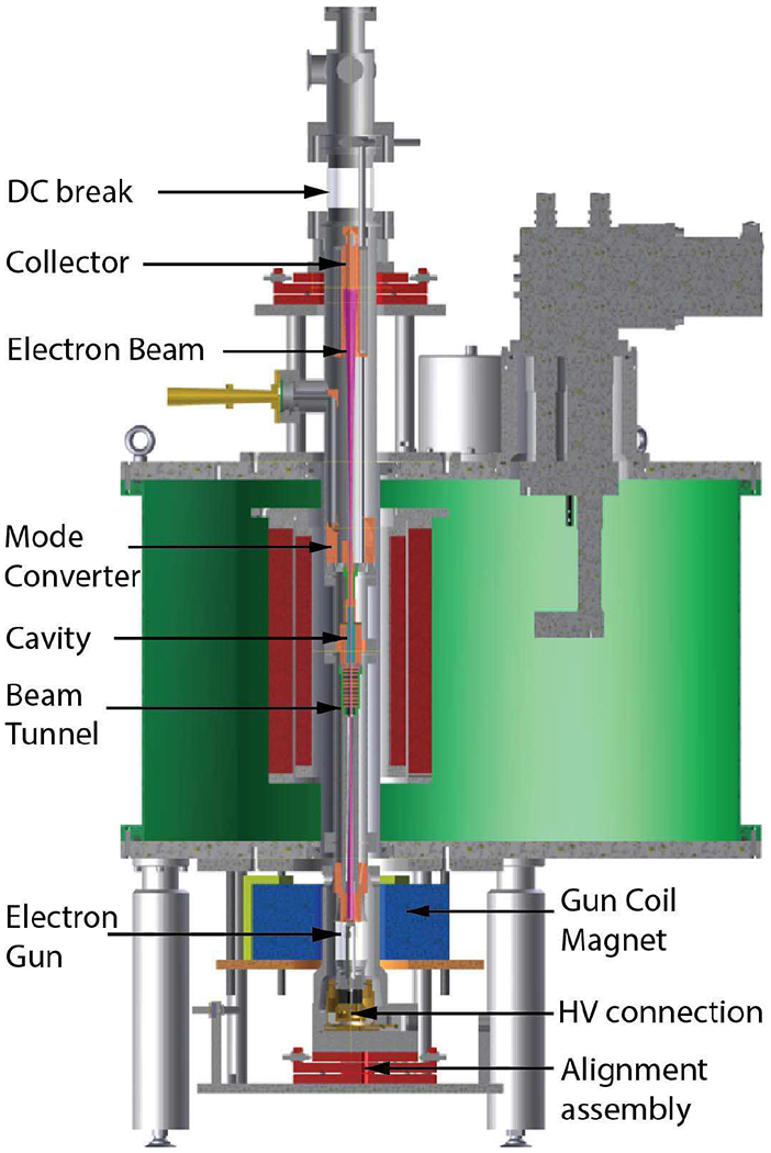
The schematic of the 527 GHz gyrotron in a 10 T SCM (shown in green) is shown. Different components of the tube assembly are labeled. The gyrotron tube is mounted on two assemblies at the top and bottom for alignment along the magnetic field axis.
TABLE I.
Design Parameters of the Gyrotron
| Parameter | Value |
|---|---|
| Frequency | 527 GHz |
| Cyclotron Harmonic | 2nd |
| Magnetic field | 9.7 T |
| Operating Mode | TE11,2,q |
| Frequency Tuning | ~ 1 GHz |
| Voltage | < 17 kV |
| Current | < 200 mA |
| Output Power | 2 – 20 W |
| Cavity length | 25 mm |
| Output mode | HE11 |
Fig. 2.
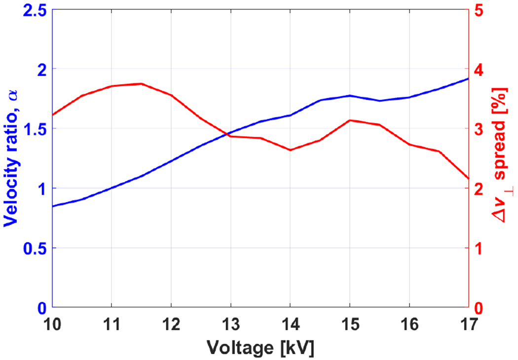
Calculated perpendicular to parallel velocity ratio, α, and perpendicular velocity spread, Δv⊥ w.r.t. the operating voltage for the diode type electron gun.
The initial design of the resonator cavity and its operating mode selection were done by calculating the coupling coefficients of various modes at 527 GHz. The operating mode-TE11,2,q, q being the axial mode index, was chosen by optimizing various factors such as maximum coupling with the electron beam of radius 0.97 mm, separation from nearby competing fundamental and second harmonic modes, ohmic loss of the operating mode etc. The choice of the TE11,2 as the operating mode was also inspired by our past success of the 460 GHz gyrotron which successfully produced over 15 W [28]. The main operating mode is the TE11,2,1 mode (q = 1), while the higher order modes, (q = 2,3,4, etc.) provide for frequency tuning. The interaction resonator cavity profile was optimized using cold cavity calculations. The total length of the cavity is ≈ 78 mm which consists of a straight resonator section of radius rc = 1.593 mm and length 25 mm and three consecutive up-tapers at 0.3°, 0.6°, and 1.9° respectively. The length of the straight resonator section is ≈ 45λ which is significantly longer compared to the length of cavities used in gyrotrons operating at power levels in the megawatts range for electron cyclotron resonance heating in fusion applications. The longer cavity was selected to consecutively excite the higher order axial modes, q, for continuous frequency tunability. Fig. 3 shows the cavity profile along with the normalized electric field amplitude of the TE11,2,1 mode. The calculated diffractive and ohmic quality factors of the operating modes are 97500/q2 and 7500, respectively, assuming the electrical conductivity equal to one half of ideal copper. The diffractive quality factor is calculated using the cold-cavity approximation.
Fig. 3.
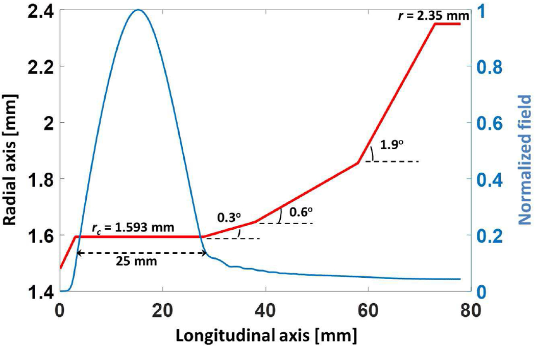
The cavity profile showing 25 mm long resonator section and up tapers. The electric field profile of TE11,2,1 mode is also shown calculated using the self-consistent multimode code MAGY [47].
After the cold cavity axial field profile and the coupling coefficients were calculated, linear theory [48] was used to calculate the start oscillation current of the main operating mode-TE11,2,1, and the neighboring competing fundamental and second harmonic modes. This is shown in Fig. 4. The transverse electric field profile of the TE11,2 mode and the circle representing the electron beam are also shown in the center of the figure. The starting current was calculated for an operating voltage of 16.7 kV, α = 1.8, re = 0.97 mm, Δv⊥/v⊥ = 3% and for first axial mode q = 1 of each mode shown in Fig. 4. It is clear that the main operating mode-TE11,2,1 is well separated from the nearest fundamental mode TE7,1,1 and the second harmonic modes TE5,4,1 and TE−8,3,1. The predicted start oscillation current for the operating mode is ~ 20 mA. The frequency tuning is accomplished by exciting a series of axial modes, TE11,2,q. The start oscillation current of these higher order axial modes (q) was also calculated and is described below with the experimental results.
Fig. 4.
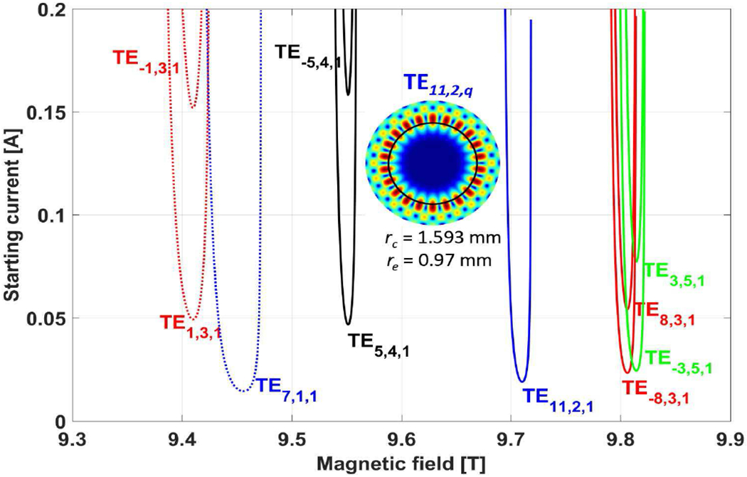
Start oscillation current of the operating mode, TE11,2,1, and the neighboring modes w.r.t. the operating magnetic field. Also shown in the center is the electric field profile of the operating mode TE11,2 in a resonator cavity of radius rc = 1.593 mm and the circle representing the electron beam of radius re = 0.97 mm.
After the interaction, the microwaves were converted from the TE11,2 mode to a Gaussian like beam using a quasi-optical mode converter assembly. The mode converter consists of a helical cut Vlasov type smooth wall mode launcher with waveguide radius of 2.35 mm and two curved mirrors, one parabolic and one spherical. The mode converter was designed using the electric-field integral equation code Surf3d [49]. After the second mirror the microwave beam was coupled into a corrugated waveguide of 12 mm diameter placed inside the tube as part of the periscope assembly with two miter-bends. Fig. 5(a) shows the fabricated and assembled mode converter assembly. This periscope assembly brings the microwaves in the form of an HE11 mode to the window. The window is made of fused quartz and mounted on a conflat flange. Fig. 5(c) shows the electric field intensity in the cut plane along the axis of the tube calculated using Surf3D and radiated from mirror 1 to mirror 2 and then to the location of the corrugated waveguide aperture shown by the dashed line. The intensity profile at the waveguide aperture is also shown in the Fig. 5(b). The calculated Gaussian mode content of the beam just before the waveguide aperture is ~ 90% and the HE11 mode content coupled to the waveguide is ~ 84%. The window used in the gyrotron tube is mounted on a CF flange and has a thickness of 3.352 mm and diameter of 42 mm.
Fig. 5.
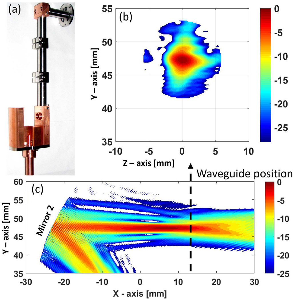
(a) Fabricated mode converter assembly, (b) Intensity profile of the Gaussian beam calculated using Surf3D in a transverse plane before coupling into the corrugated waveguide. (c) Intensity profile for the radiated field after the 1st mirror and in a cut plane showing the position of 2nd mirror and the corrugated waveguide aperture.
The beam tunnel of the gyrotron consists of a section of axially slotted stainless-steel tube and a section of SiC and copper loaded disks to suppress any parasitic oscillations. The SiC is a standard absorbing material used in the gyrotron beam tunnel for low frequency oscillation suppression. The dielectric constant and loss tangent of different grades of the SiC used in gyrotron beam tunnels are ε = 11.5 to 13.5 and tan δ = 0.02 to 0.06 [50, 51].
The collector is a simple undepressed water cooled collector at ground potential with respect to the cathode. The collector and cavity cooling requirements were calculated from the electron beam power used in the operation and the generated microwave power in the cavity from beam wave interaction. The cooling circuits were fabricated accordingly. All components were fabricated and tested in-house. A water chiller of cooling capacity of 5 kW is used in the experiment to meet the cooling requirements of the cavity and the collector The cathode emitter was purchased from 3M Ceradyne Inc. A photograph of the installed gyrotron operating in the lab is shown in Fig. 6.
Fig. 6.
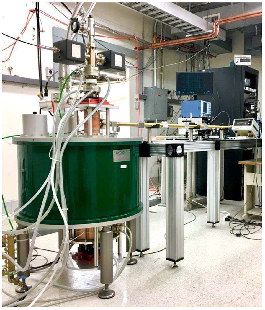
Photograph of the 527 GHz gyrotron tube under test. A 10 T cryo-free superconducting magnet (green color) is seen in the picture along with the gyrotron tube and a small magnet coil, at the bottom of the main magnet, for fine tuning the electron beam parameters. A 16 mm i.d. corrugated waveguide transmission line made of brass is also seen in the picture.
III. Experimental Results
The gyrotron was operated from 15 kV to 17 kV operating voltage and at magnetic field of 9.68 T to 9.75 T and the output power and frequency were measured. The internal corrugated waveguide positions the microwave beam at the center of the quartz window for coupling to the outside corrugated taper of 12 mm to 16 mm i.d. After the corrugated taper the beam is coupled into a 3 m long 16 mm i.d. corrugated waveguide. The corrugated waveguides were machined for operation at 527 GHz [52]. The output power was measured using a calibrated Scientech power meter. The calibration was verified using another THz power meter 3A-P-THz from Ophir Optronics Sol.
The start oscillation current of the operating modes, TE11,2,q, was first measured at an operating voltage of 16.7 kV and the gun coil magnet operating at ~ −37 mT. The magnetic field was varied from 9.69 T to 9.75 T. The microwave output levels were measured using the 3A-P-THz power meter capable of measuring down to 0.1 mW of power. The measured start oscillation current is plotted in Fig. 7 along with the calculated start current of the axial modes TE11,2,q, for q = 1 to 4, using the linear theory. The linear theory assumes a fixed axial field structure leading to separate starting current estimates for each axial mode q. In practice, these axial modes are coupled through the electron beam and form a continuously tunable range of output frequencies [53]. A minimum start current of ~ 21 mA is observed experimentally. An excellent agreement is seen between the measured minimum start current and the theoretical start current for axial modes q = 1,2,3,4.
Fig. 7.
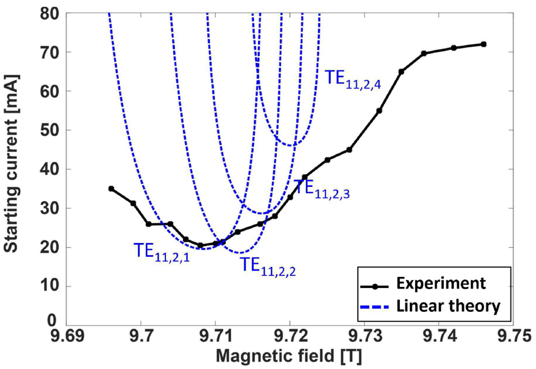
The measured (solid black line with dots) and calculated (dashed blue lines) start oscillation current of the operating mode TE11,2,q, q = 1,2,3,4 for different magnetic field values. A minimum start current of ~ 21 mA is observed. The calculated start current assumed cold cavity electric field profile in the linear theory for cavity radius of rc = 1.593 and operating voltage of V = 16.7 kV, α = 1.8 and Δv⊥ = 3% with the gun coil magnetic field of ~ −37 mT.
The gyrotron was operated for measuring the power and frequency at a magnetic field of 9.708 T. The maximum output power of 9.3 W was observed for the operating voltage of 16.7 kV and beam current of 110 mA. The measured frequency at maximum power was 527.2 GHz. The measured power and frequency by varying the voltage at fixed magnetic field is shown in Fig. 8. In the voltage tuning measurement, the gun coil magnet was varied up to −35 mT to maximize the output power. The lowest frequency of 527.12 GHz is observed with output power of 9.0 W. A total of ~ 0.35 GHz continuous frequency tuning is observed. The output frequency is measured using an even harmonic mixer (EHM) in the WR1.9 frequency band from VDI Inc, and a heterodyne system with a local oscillator (LO) synthesizer operating at 18 GHz to 26 GHz. The output signal was verified by observing consecutive harmonics of the LO on a 2.5 GHz bandwidth oscilloscope. Fig. 9 shows the magnetic field tuning for output power and frequency at a fixed voltage of 16.7 kV. A total frequency tuning of ~ 0.25 GHz is observed by varying the magnetic field. The multimode self-consistent nonlinear code MAGY [47] is used to theoretically calculate the output power and frequency by varying the magnetic field. The results are shown in Fig. 10 for the operating parameters used in Fig. 9. The operating voltage of 16.7 kV and beam current of 110 mA, α = 1.85 and Δv⊥/v⊥ = 5% were used in simulations. The conductivity used in the calculations is one half of the ideal copper conductivity. The magnetic field center and the resonator cavity center are axially aligned in the simulations based on the tube position in the actual experiment for better comparison between the theory and experiments. The cavity radius used in the calculations is the actual measured cavity radius of rc = 1.593 mm. Although the velocity spread value calculated from MICHELLE is 2.5%, as shown in Fig. 2, in MAGY calculations we use 5% as it shows better agreement with the experiments. It is not unusual that the velocity spread value in reality is higher than the calculations because there are additional contributors to it which are not fully considered in simulations in detail, such as misalignments in the gun assembly, emitter surface roughness and temperature nonuniformity. A theoretical frequency tuning of ~ 320 MHz is observed by varying the magnetic field by successive excitation of axial modes, q. A very good qualitative agreement can be seen between the theory of Fig. 10 and the experimental results of Fig. 9 for both frequency tuning and output power considering the ~ 86% efficiency of the Vlasov type mode converter. The overall frequency tunability of ~ 0.4 GHz is observed by combining the voltage and magnetic tuning. An output power of more than 4 W is observed for ~ 0.35 GHz of frequency variation. This is shown in Fig. 11. The voltage is varied from 15.5 kV to 17.0 kV and the magnetic field is varied from 9.69 T to 9.75 T and the gun coil field is varied from −25 mT to −35 mT. By careful alignment of the gyrotron tube in the magnet bore in transverse and axial directions it was verified that the gyrotron is operating in the second harmonic TE11,2 mode and no spurious modes, fundamental or second harmonic, were excited. The output power was also measured by varying the beam current at fixed voltage of 16.7 kV and magnetic field of 9.71 T. This is shown in Fig. 12. The gyrotron was operated continuously for 96 hours under computer control. The variation in power was less than 2% and the frequency was stable to within 2 MHz. No thermal issues were discovered during the operation of the gyrotron. For CW operation, the water temperature and flow rate at both the cavity and collector cooling channels are monitored in real time in LabView.
Fig. 8.
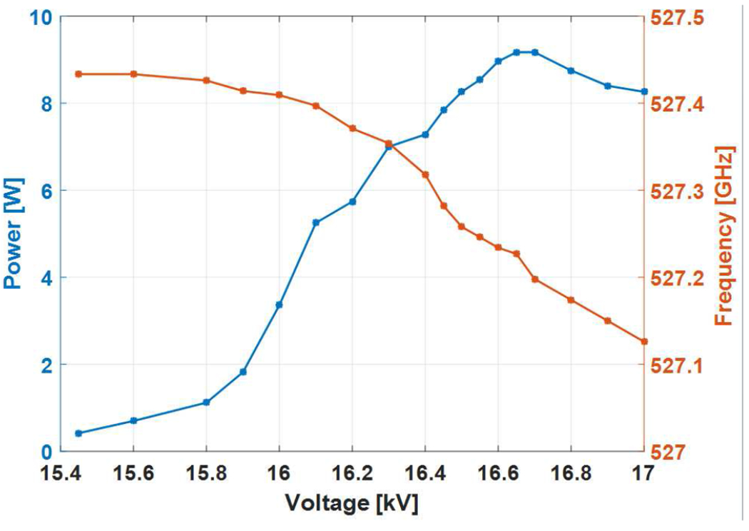
The measured output power and frequency with respect to the operating voltage at the magnetic field of 9.708 T and 110 mA of electron beam current. The gun coil magnet is operated up to ~ −35 mT to maximize the output power.
Fig. 9.
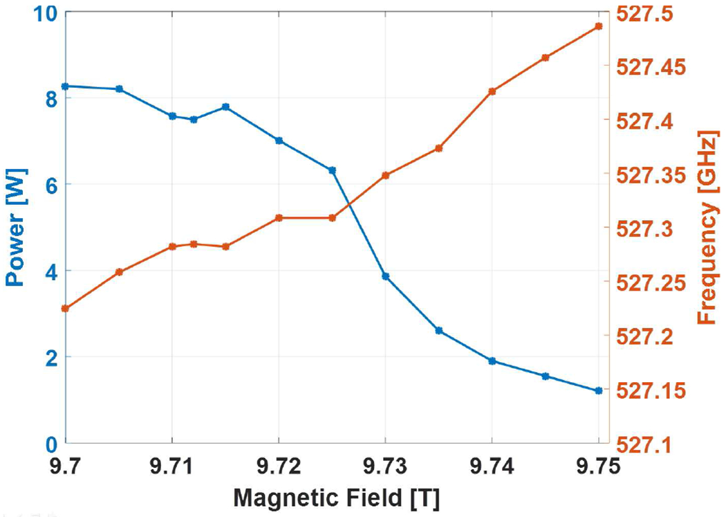
The measured output power and frequency with respect to the operating magnetic field and fixed voltage of 16.7 kV and 90 mA of electron beam current. The gun coil magnet is operated up to ~ −35 mT to maximize the output power.
Fig. 10.
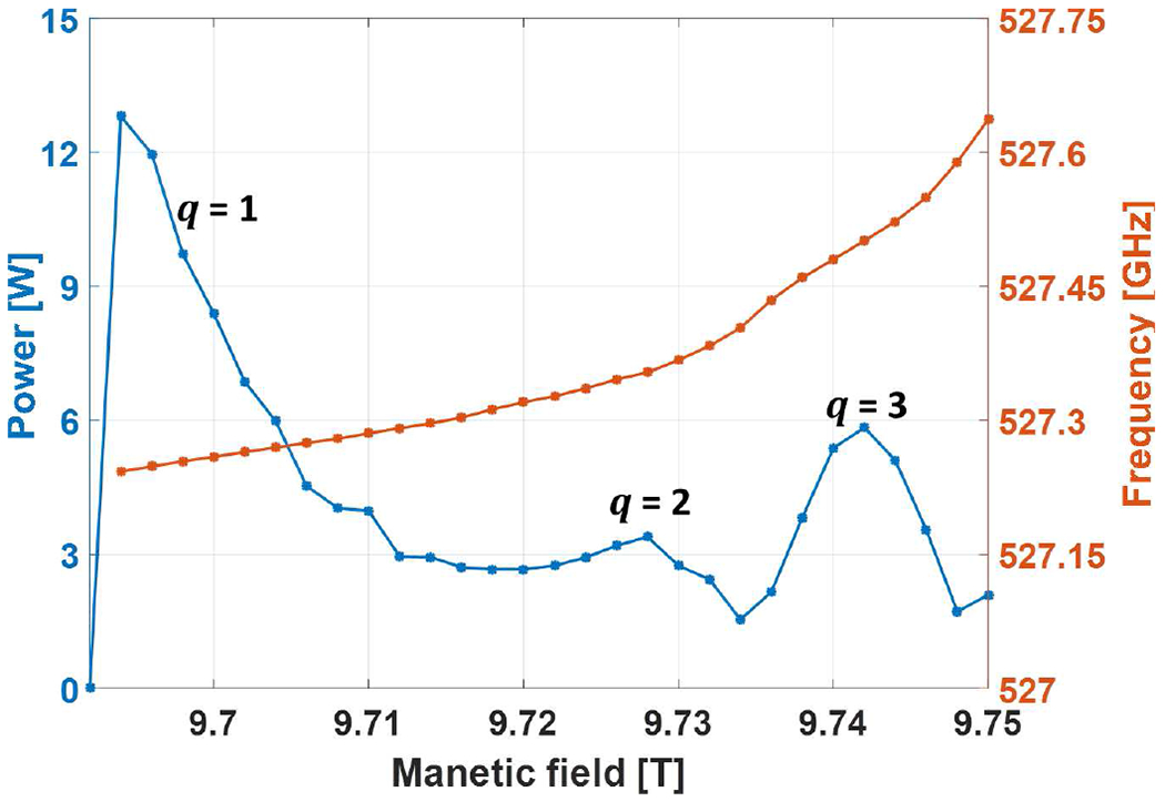
The simulated output power and frequency with respect to the operating magnetic field at 16.7 kV voltage and 110 mA of electron beam current, α = 1.85 and Δv⊥/v⊥ = 5%. The cavity radius used in the calculations is the measured radius of 1.593 mm.
Fig. 11.
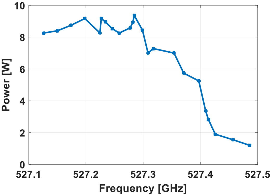
The measured output power as a function of output frequency for varying magnetic field from 9.69 T to 9.75 T and voltage varying from 15.5 to 17 kV at a beam current of 110 mA.
Fig. 12.
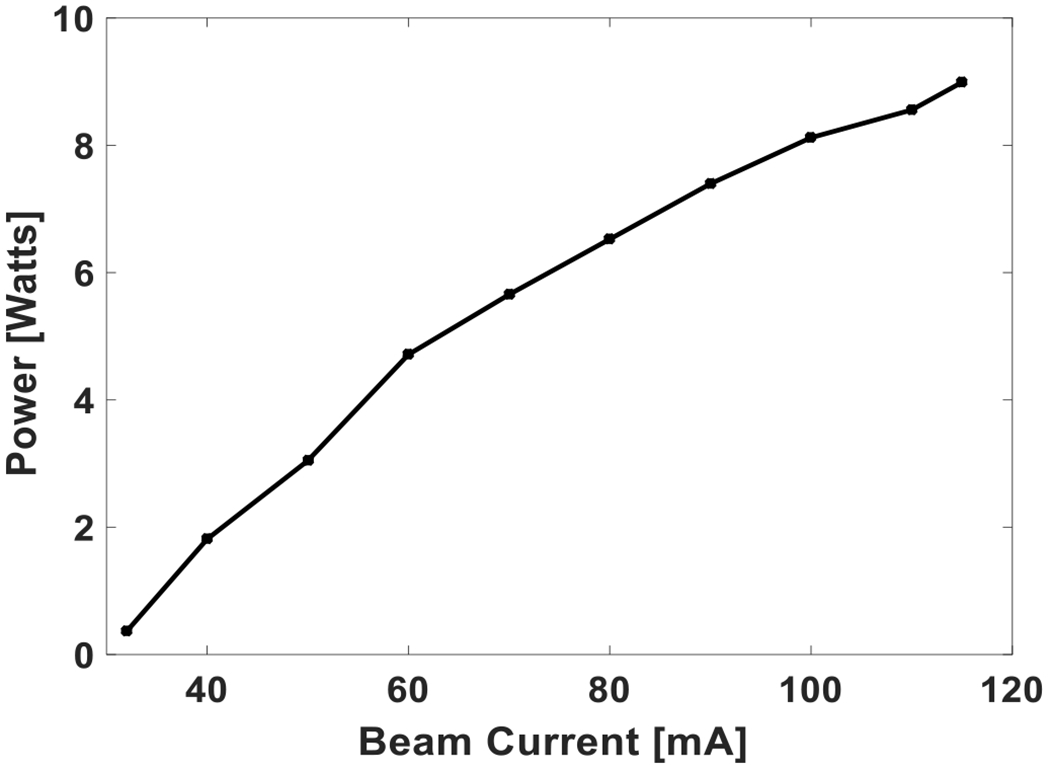
The measured output power with respect to the beam current at magnetic field of 9.71 T and 16.7 kV voltage.
The output of the gyrotron is coupled into a 16 mm i.d. corrugated waveguide using a corrugated taper from 12 mm i.d. to 16 mm, with expected loss of less than 1% [52]. The corrugated waveguides of 30 cm-long sections are fabricated in house using a helical tap of nearly square shape corrugation [54] where depth and width of the corrugations are adapted for operation at ~ 527 GHz. The waveguides are aligned and the beam profile at the end of the ~ 3 m long section of corrugated waveguide is measured using a pyroelectric camera. The field profile was measured in a few different locations along the waveguide axis parallel to the aperture. The measured field profiles at 20 mm and 38 mm from the waveguide aperture are shown in Fig. 10. The calculated Gaussian content of the propagated field is ~ 92%. The field measured in different locations along the waveguide axis was used to retrieve the phase of the beam and propagated back to the aperture [55]. The HE11 mode content of the field is thus measured to be ~ 84%.
IV. Conclusions
We have designed, fabricated and experimentally tested a 527 GHz gyrotron operating at the second harmonic. The gyrotron has generated an output power of 9.3 Watts at 16.7 kV and 110 mA. This corresponds to an operating efficiency of ~ 0.5%. Higher output power can be expected by further raising the operating beam current. This may be possible after additional processing of the gyrotron. The excitation of consecutive higher order axial modes by voltage and magnetic field variation led to a frequency tunability of 0.4 GHz. An output power of more than 4 W was observed for this frequency bandwidth. The output beam of the gyrotron is in the form of a corrugated waveguide HE11 mode with ~ 84 % HE11 mode content.
Fig. 13.
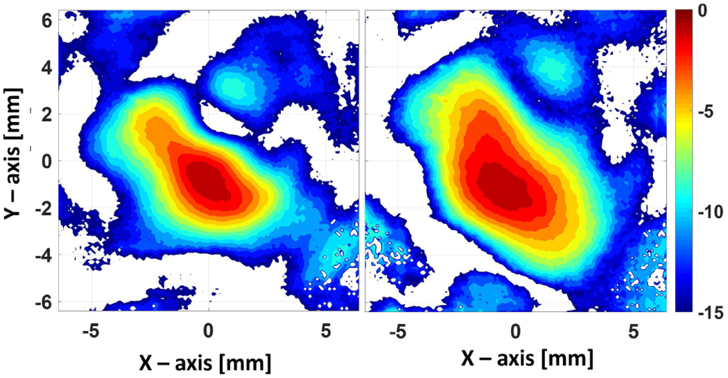
The measured intensity profile at 20 mm (left) and 38 mm (right) from the waveguide aperture after a 3 m long waveguide section using a pyroelectric camera.
Acknowledgments
This project is funded by the National Institutes of Health, NIBIB under grants R01-EB004866, R01-EB001965, and NIGMS under grants GM132079 and GM132997.
Contributor Information
Sudheer K. Jawla, Plasma Science and Fusion Center, Massachusetts Institute of Technology, Cambridge, MA 02139 USA.
Robert G. Griffin, Department of Chemistry and the Francis Bitter Magnet Laboratory, Massachusetts Institute of Technology, Cambridge, MA 02139 USA
Ivan A. Mastovsky, Plasma Science and Fusion Center, Massachusetts Institute of Technology, Cambridge, MA 02139 USA
Michael A. Shapiro, Plasma Science and Fusion Center, Massachusetts Institute of Technology, Cambridge, MA 02139 USA.
Richard J. Temkin, Department of Physics and the Plasma Science and Fusion Center, Massachusetts Institute of Technology, Cambridge, MA 02139.
References
- [1].Abragam A, Goldman M, “Principles of dynamic nuclear polarization”, Reports on Progress in Physics, 41 (3), 395, 1978. [Google Scholar]
- [2].Goldman M, Spin temperature and nuclear magnetic resonance in solids, Oxford University Press: London, 1970. [Google Scholar]
- [3].Griffiths JM, Lakshmi KV, Bennett AE, Raap J, Vanderwielen CM, Lugtenburg J, Herzfeld J, Griffin RG, “Dipolar correlation NMR-spectroscopy of a membrane protein”, J. Am. Chem. Soc, 116, 10178–10181, 1994. [Google Scholar]
- [4].Castellani F, van Rossum B, Diehl A, Schubert M, Rehbein K, Oschkinat H, “Structure of a protein determined by solid-state magic-angle-spinning NMR spectroscopy”, Nature, 420, 98–102, 2002. [DOI] [PubMed] [Google Scholar]
- [5].Maly T, Debelouchina GT, Bajaj VS, Hu KN, Joo CG, Mak-Jurkauskas ML, Sirigiri JR, Wel PC, Herzfeld J, Temkin RJ, Griffin RG, “Dynamic Nuclear Polarization at High Magnetic Fields”, J. Chem. Phys, 128, 052211, 2008. [DOI] [PMC free article] [PubMed] [Google Scholar]
- [6].Ni QZ, Daviso E, Can TV, Markhasin E, Jawla S, Swager TM, Temkin RJ, Herzfeld J and Griffin RG, “High frequency dynamic nuclear polarization”, Acc. Chem. Res, (2013), 46, 1933–1941. [DOI] [PMC free article] [PubMed] [Google Scholar]
- [7].Becerra RL, Gerfen GJ, Temkin RJ, Singel DJ, Griffin RG, “Dynamic nuclear polarization with a cyclotron resonance maser at 5 T”. Physical Review Letters, 71 (21), 3561, 1993. [DOI] [PubMed] [Google Scholar]
- [8].Flyagin VA, Gaponov AV, Petelin MI, Yulpatov VK, “The Gyrotron”, IEEE Trans. on Microwave Theory and Techniques, 25 (6), 514, 1977. [Google Scholar]
- [9].Thumm M, Denisov GG, Sakamoto K and Tran MQ, “High-power gyrotrons for electron cyclotron heating and current drive”, Nuclear Fusion, 59 (2019) 073001. [Google Scholar]
- [10].Felch K, Blank M. Borchard P et al. , “Operating experience on six 110 GHz, 1 MW gyrotrons for ECH applications”, Nuclear Fusion, 48 (2008) 054008. [Google Scholar]
- [11].Bratman VL, Bogdashov AA, Denisov GG, Glyavin M.Yu.. , et al. , “Gyrotron development for high power THz technologies at IAP RAS,” J. Infrared Millimeter and Terahertz Waves, vol. 33 pp. 715–723, 2012. [Google Scholar]
- [12].Kariya T, Minami R, Imai T, Okada M, Motoyoshi F, Numakura T, Nakashima Y, Idei H, Onchi T, Hanada K, Shimozuma T, Yoshimura Y, Takahashi H, Kubo S, Oda Y, Ikeda R, Sakamoto K, Ono M, Nagasaki K, Eguchi T, Mitsunaka Y, “Development of high power gyrotrons for advanced fusion devices”, Nuclear Fusion, 59 (2019) 066009. [Google Scholar]
- [13].Nusinovich GS, Introduction to the physics of gyrotrons (Johns Hopkins Studies in Applied Physics); Johns Hopkins University Press, 2004. [Google Scholar]
- [14].Sakamoto K, Ikeda R, Kariya T, Oda Y, Kobayashi T, Kajiwara K, Hayashi K, Minami R, Takahashi K, Imai T, Moriyama S, “Study of high power and high frequency gyrotron for fusion reactor”, 42nd Int. Conf. on Infrared, Millimeter, and Terahertz Waves (IRMMW-THz), 2017. [Google Scholar]
- [15].Avramidis KA , Aiello G, Alberti S, Thomas Brucker P, Brnschi A, Chelis I, Franke T, et al. , “Overview of recent gyrotron R&D towards DEMO within EURO fusion work package heating and current drive”, Nuclear Fusion, 59 (2019) 066014. [Google Scholar]
- [16].Woskov PP, Machuzak JS, Myer RC, Cohn DR, Bretz NL, Efthimion PC, and Doane JL, “Gyrotron collective Thomson scattering diagnostic for confined alpha particles in TFTR, Rev. of Scientific Instruments, 59, 1565 (1988). [Google Scholar]
- [17].Yamaguchi Y, et al. , “High-power pulsed gyrotron for 300 GHz-band collective Thomson scattering diagnostics in the Large Helical Device”, Nuclear Fusion, 55 (2015) 013002. [Google Scholar]
- [18].Yamazaki T, Miyazaki A, Suehara T, Namba T, et al. , “Direct observation of the hyperfine transition of ground — state positronium,” Phys. Rev. Lett, vol. 108, pp. 253401, 2012. [DOI] [PubMed] [Google Scholar]
- [19].Hoshizuki H, Mitsudo S, Saji T, Matsuura K, Idehara T, Glyavin M, Eremeev A, Honda T, Iwai T,Y, Nishi H, Kitano A, Ishibashi J, “High temperature thermal insulation system for millimeter wave sintering of B4C”, International Journal of Infrared and Millimeter Waves, vol. 26, no. 11, pp. 153–1541, 2005. [Google Scholar]
- [20].Hummelt JS, Shapiro MA, Temkin RJ, “Spectroscopic temperature measurements of air breakdown plasma using a 110 GHz megawatt gyrotron beam”, Physics of Plasmas, vol. 19, Issue 12, pp. 123509, 2012. [Google Scholar]
- [21].Han S-T, “Real-time, T-Ray imaging using a sub-terahertz gyrotron,” Journal of the Korean Physical Society, vol. 60, no. 11, 1857–1861, 2012. [Google Scholar]
- [22].Nusinovich GS, Sprangle P, Semenov VE, Dorozhkina DS, and Glyavin M.Yu.., “On the sensitivity of terahertz gyrotron based systems for remote detection of concealed radioactive materials”, Journal of Applied Physics, 111, 124912 (2012). [Google Scholar]
- [23].Nanni EA, Dolgashev V, Jawla S, Neilson J, Othman M, Picard J, Schaub S, Spataro B, Tantawi S, Temkin RJ, “Results from mm-Wave Accelerating Structure High-Gradient Tests”, 43rd International Conference on Infrared, Millimeter, and Terahertz Waves (IRMMW-THz), 2018, [Google Scholar]
- [24].Picard JF, Schaub SC, Rosenzweig G, Stephens JC, Shapiro MA, and Temkin RJ, “Laser-driven semiconductor switch for generating nanosecond pulses from a megawatt gyrotron”, Appl. Phys. Lett, 114, 164102 (2019) [DOI] [PMC free article] [PubMed] [Google Scholar]
- [25].Spira-Hakkarainen S, Kreischer KE, and Temkin RJ, “Submillimeter-wave harmonic gyrotron experiment,” IEEE Trans. Plasma Sci, vol. 18, no. 3, pp. 334–342, 1990. [Google Scholar]
- [26].Hornstein MK, Bajaj VS, Griffin RG, Kreischer KE, Mastovsky I, Shapiro MA, Sirigiri JR, and Temkin RJ, “Second harmonic operation at 460 GHz and broadband continuous frequency tuning of a gyrotron oscillator,” IEEE Trans. Electron Devices, vol. 52, no. 5, pp. 798–807, 2005. [Google Scholar]
- [27].Torrezan AC, Shapiro MA, Sirigiri JR, Temkin RJ, Griffin RG, “Operation of a continuously frequency-tunable second-harmonic CW 330-GHz gyrotron for dynamic nuclear polarization”. IEEE Trans. on Electron Devices2011, 58 (8), 2777. [Google Scholar]
- [28].Torrezan AC, Han ST, Mastovsky I, Shapiro MA, Sirigiri JR, Temkin RJ, Barnes AB, Griffin RG, “Continuous-wave operation of a frequency-tunable 460-GHz second-harmonic gyrotron for enhanced nuclear magnetic resonance”, IEEE Trans. on Plasma Science,2010, 38 (6), 1150. [DOI] [PMC free article] [PubMed] [Google Scholar]
- [29].Barnes AB, Nanni EA, Herzfeld J, Griffin RG, Temkin RJ, “A 250GHz gyrotron with a 3GHz tuning bandwidth for dynamic nuclear polarization”, Journal of Magnetic Resonance, 221, 147, 2012. [DOI] [PMC free article] [PubMed] [Google Scholar]
- [30].Jawla S, Ni QZ, Barnes AB, Guss W, Daviso E, Herzfeld J, Griffin RG, Temkin RJ, “Continuously tunable 250 GHz gyrotron with a double disk window for DNP-NMR spectroscopy”, Journal of Infrared, Millimeter, and Terahertz Waves, 34 (1), 42, 2012. [DOI] [PMC free article] [PubMed] [Google Scholar]
- [31].Blank M, Borchard P, Cauffman S, Felch K, Rosay M and Tometich L, “Development of high frequency CW gyrotrons for DNP/NMR application,” Proc. of IVEC 2013 Intl. Vac. Electron. Conf., Paris, France, (2013). [Google Scholar]
- [32].Blank M, Felch K, “Millimeter-wave sources for DNP-NMR”, eMagRes, vol. 7, issue 4, pp. 155–166, 2018. [Google Scholar]
- [33].Alberti S , Ansermet J.-Ph. Avramides KA ,Braunmueller F , et al. , “Experimental study from linear to chaotic regimes on a terahertz-frequency gyrotron oscillator”, Phys. of Plasmas, 19, 123102 (2012). [Google Scholar]
- [34].Glyavin M. Yu., Chirkov AV, Denisov GG, Fokin AP, Kholoptsev VV, et al. , “Experimental tests of a 263 GHz gyrotron for spectroscopic applications and diagnostics of various media”, Rev. Sci. Instrum. 86 (5):054705, 2015. [DOI] [PubMed] [Google Scholar]
- [35].Tatematsu Y, Yamaguchi Y, Idehara T, Kawase T, Ichioka R, et al. , “Development of second harmonic gyrotrons, Gyrotron FU CW GII and Gyrotron FU CW GIII, equipped with internal mode converters”, J. Infrared Millim. Terahertz Waves, vol. 35, Issue 2, pp 169–178, 2014. [Google Scholar]
- [36].Jawla S, Reese M, George C, Chen Y, Shapiro M, Griffin R, Temkin R, “-330 GHz / 500 MHz dynamic nuclear polarization-NMR spectrometer”, International Conference on Infrared, Millimeter, and Terahertz Waves (IRMMW-THz), 2016. [Google Scholar]
- [37].Reese M, George C, Yang C, Jawla S, Temkin R, Redfield C and Griffin RG, “Modular, triple-resonance, transmission line DNP MAS probe for 500 MHz/330 GHz”, Journal of Magnetic Resonance, (submitted), 2019. [DOI] [PMC free article] [PubMed] [Google Scholar]
- [38].Barnes AB, Markhasin E, Daviso E, Michaelis VK, Nanni EA, Jawla SK, Mena EL, DeRocher R, Thakkar A, Woskov PP, et al. “Dynamic nuclear polarization at 700MHz/460GHz”, Journal of Magnetic Resonance,224, 1, 2012. [DOI] [PMC free article] [PubMed] [Google Scholar]
- [39].Ikeda R, Yamaguchi Y, Tatematsu Y, Idehara T, Ogawa I, Saito T, Matsuki Y, Fujiwara T, “Broadband continuously frequency tunable gyrotron for 600 MHz DNP-NMR spectroscopy”, Plasma and Fusion Research, 9 (0), 1206058, 2014. [Google Scholar]
- [40].Manuilov VN, Glyavin MY, Sedov AS, Zaslavsky VY, Idehara T, “Design of a second harmonic double-beam continuous wave gyrotron with operating frequency of 0.79 THz”. Journal of Infrared, Millimeter, and Terahertz Waves 36 (12), 1164, 2015. [Google Scholar]
- [41].Idehara T, Kosuga K, Agusu L, Ikeda R, Ogawa I, Saito T, Matsuki Y, Ueda K, Fujiwara T, “Continuously frequency tunable high-power sub-THz radiation source-gyrotron FU CW VI for 600 MHz DNP-NMR spectroscopy”, Journal ofInfrared, Millimeter, and Terahertz Waves, 31 (7), 775, 2010. [Google Scholar]
- [42].Idehara T, Tatematsu Y, Yamaguchi Y, Khutoryan EM, Kuleshov AN, Ueda K, Matsuki Y, Fujiwara T, “The development of 460 GHz gyrotrons for 700 MHz DNP-NMR spectroscopy”, Journal of Infrared, Millimeter, and Terahertz Waves 36 (7), 613, 2015. [Google Scholar]
- [43].Rozier Y, Legrand F, Lievin C, Racamier J-C, Marchesin R. Alberti S, Braunmueller F, Hogge J.-Ph., da Silva M, Tran MQ, Tran TM, Macor A, “Manufacturing of a 263 GHz continuously tunable gyrotron”, IEEE 14th International Vacuum Electronics Conference (IVEC), 2013. [Google Scholar]
- [44].Rosay M, Tometich L, Pawsey S, Bader R, Schauwecker R, Blank M, Borchard P, Cauffman S, Felch K, Weber R, et al. “Solid-state dynamic nuclear polarization at 263 GHz: spectrometer design and experimental results”, Physical Chemistry Chemical Physics,12 (22), 5850, 2010. [DOI] [PMC free article] [PubMed] [Google Scholar]
- [45].Yoon D, Soundararajan M, Cuanillon P, Braunmueller F, Alberti S, Ansermet J-P, “Dynamic nuclear polarization by frequency modulation of a tunable gyrotron of 260 GHz”, Journal of Magnetic Resonance, 262, 62–67, 2016. [DOI] [PubMed] [Google Scholar]
- [46].Petillo J, Eppley K, Panagos D, Blanchard P, Nelson E, et al. , “The MICHELLE three-dimensional electron gun and collector modeling tool: theory and design”, IEEE Trans. Plasma Sci, vol. 30, pp. 1238–1264, 2002. [Google Scholar]
- [47].Botton M, Antonsen TM Jr, Levush B , Nguyen KT, Vlasov AN, “MAGY: A time-dependent code for simulation of slow and fast microwave sources”, IEEE Trans. Plasma Sci, vol. 26, no. 3, pp. 882–892, 1998. [Google Scholar]
- [48].Danly BG and Temkin RJ, “Generalized nonlinear harmonic gyrotron theory”, Physics of Fluids, 29, 561 (1986). [Google Scholar]
- [49].Neilson JM and Bunger R, “Surface integral equation analysis of quasioptical launcher,” IEEE Trans. Plasma Sci, vol. 30, no. 3, pp. 794–799, 2002. [Google Scholar]
- [50].Shoyama H, Sakamoto K, Hayashi K, Kasugai A, Tsuneoka M, Takahashi K, Ikeda Y, Kariya T, Mitsunaka Y, and Imai T, “High efficiency oscillation of 170 GHz high-power gyrotron at TE31,8 mode using depressed collector,” Jpn. J. Appl. Phys, vol. 40, no. 8B, pp. L906–L908, Aug. 2001. [Google Scholar]
- [51].Genoud Jérémy, Advanced linear models for gyro-backward wave instabilities in gyrotrons, PhD thesis, 2019. [Google Scholar]
- [52].Schaub SC, Shapiro MA, and Temkin RJ, “Simple Expressions for the Design of Linear Tapers in Overmoded Corrugated Waveguides”, J. Infrared Milli. Terahertz Waves, vol. 37, issue 1, pp. 100–110, 2016. [DOI] [PMC free article] [PubMed] [Google Scholar]
- [53].Genoud J, Tran TM, Alberti S, Braunmueller F, Hogge J.-Ph , Tran MQ, Guss WC, and Temkin RJ, “Novel linear analysis for a gyrotron oscillator based on a spectral approach”, Physics of Plasmas, 23, 043101 (2016). [Google Scholar]
- [54].Nanni EA, Jawla SK, Shapiro MA, Woskov PP, Temkin RJ, “Low-loss Transmission Lines for High-power Terahertz Radiation”, J. of Infrared, Milli. Terahertz Waves, 33 (7), 695, 2012. [DOI] [PMC free article] [PubMed] [Google Scholar]
- [55].K Jawla S, Nanni EA, Shapiro MA, Woskov PP, Temkin RJ, “Mode content determination of terahertz corrugated waveguides using experimentally measured radiated field patterns”, IEEE Trans. on Plasma Science,40 (6), 1530–1537, 2014. [DOI] [PMC free article] [PubMed] [Google Scholar]


