Abstract
X-ray acoustic imaging is a hybrid biomedical imaging technique that can acoustically monitor X-ray absorption distribution in biological tissues through the X-ray induced acoustic effect. In this study, we developed a 3D volumetric X-ray-induced acoustic computed tomography (XACT) system with a portable pulsed X-ray source and an arc-shaped ultrasound array transducer. 3D volumetric XACT images are reconstructed via the back-projection algorithm, accelerated by a custom-developed graphics processing unit (GPU) software. Compared with a CPU-based software, the GPU software reconstructs an image over 40 times faster. We have successfully acquired 3D volumetric XACT images of various lead targets, and this work shows that the 3D volumetric XACT system can monitor a high-resolution X-ray dose distribution and image X-ray absorbing structures inside biological tissues.
1. Introduction
Since the 1950s, when X-ray induced acoustic (XA) waves were first observed, XA imaging has been studied to monitor the distribution of X-ray absorptive targets in biological tissues [1–4]. The principle of XA imaging is similar to that of laser based photoacoustic (PA) imaging. With carefully selected wavelengths of excitation light, PA imaging can provide anatomical, functional, and molecular information about biological tissues [5–19]. However, since optical light is strongly scattered in biological tissues, the light penetration is significantly limited, and consequently the PA imaging depth is relatively shallow compared to that of conventional medical imaging modalities. However, because X-rays travel in straighter paths than optical light, using X-rays with wavelengths shorter than those of optical light allows us to transmit more energy deeper into the body [20]. After bodily targets absorb pulsed X-ray irradiation, they generate ultrasound (US) waves through thermo-elastic expansion. By detecting these generated US waves with a US transducer, it is possible to delineate the distribution of the X-ray absorbers [21,22]. The initial pressure rise of the XA wave is as follows [23]:
| (1) |
where is the XA wave pressure at location and time t, is the detector transducer location, vs is the speed of sound, β is the thermal coefficient of volume expansion, Cp is the heat capacity at constant pressure, and is the heating function of thermal energy conversion. By assuming the detector transducer location as the origin for convenience, the pressure of the XA wave can be expressed as follows [24]:
| (2) |
XA imaging has been the subject of much recent research. Hickling et al. and Kim et al. demonstrated XA-based dosimetry monitoring with a medical linear accelerator and a single element US transducer [25,26]. Xiang et al. and Hao et al. demonstrated X-ray induced acoustic computed tomography (XACT) of lead and soft-tissue phantoms, using a clinical linear accelerator and a single element US transducer [21,27]. Single element US transducers were used for XA imaging in all these studies, but obtaining 2D cross-sectional images with a single element US transducer requires slow mechanical scanning, which results in excessive X-ray exposure at the imaging target. As an alternative, multi-element array US transducers can reduce the scanning time through multi-channel data acquisition, and consequently X-ray exposure can be minimized. Tang et al. reported XACT of lead samples with a 128-element ring array transducer [28]. However, this system requires many averages (e.g., 3800 times) to improve the signal to noise ratio (SNR) and provides only a 2D tomographic image.
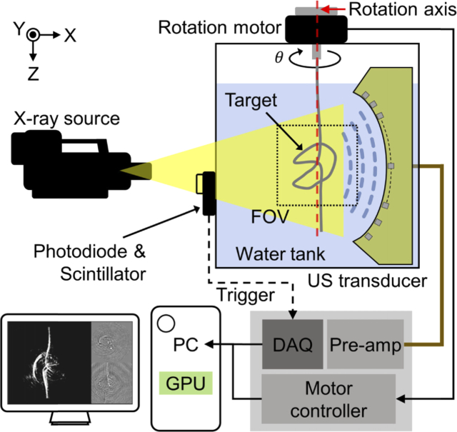
For the first time to our knowledge, we present a 3D volumetric XACT system using an arc-shaped US array transducer (96 elements) with a central frequency of 1 MHz, a 96-channel data acquisition (DAQ) board, and a sample rotary stage. By rotating the imaged sample on the azimuth axis passing through the focal point of the arc-shaped US array transducer (Rotation axis in Fig. 1), we acquired XA signals from multiple directions, which were used to reconstruct 3D volumetric XACT images by using custom-developed GPU-accelerated software for processing the back-projection algorithm [29]. We acquired 3D volumetric XACT images of various lead targets in water, and successfully obtained XACT images of lead targets embedded in chicken tissues. The results show the high potential of the developed 3D volumetric XACT system for monitoring high-resolution X-ray dose distributions and for imaging X-ray absorbing structures inside biological tissues.
Fig. 1.
Schematic of a 3D volumetric X-ray induced acoustic computed tomography system.
2. Materials and methods
2.1. X-ray acoustic computed tomography system
Figure 1 is a schematic of the 3D volumetric XACT system. A portable pulsed X-ray tube (XRS-3, Golden Engineering, USA) provides XA excitation. The X-ray tube achieves a tube potential of 270 kVp, a repetition rate of 15 Hz, a pulse width of 50 ns, and an exposure level of 2.6 ∼ 4.0 mR/pulse. The X-ray beam is delivered to the imaged target with a divergence angle of 40° (0.73 m in diameter at 1 m distance). For XA signal detection, we used a 96-element arc-shaped US array transducer with a center frequency of 1.03 MHz and a fractional bandwidth (-6 dB) of 60%, ranging from 0.73 MHz to 1.34 MHz (12645-1001, IMASONIC SAS, France), together with a 96-channel analog-to-digital converter (ADAQ96, Photosound Inc., USA). The radius of curvature of the arc-shaped US array transducer is 65 mm, the pitch size of each element is 1.4 mm, and the gap of each element is 0.1 mm. The average sensitivity of all 96 elements is 9 mV with a minimum value of 4.1 mV and a maximum value of 13.1 mV. The sensitivity homogeneity is 10.8 dB. By rotating the imaging target on the azimuth axis, it can be assumed that the US transducer elements are distributed in a spherical shape with a radius of 65 mm. The DAQ board records 3072 data points at a sampling rate of 31.3 MHz for each transducer element, resulting in approximately 100 µs record length during which ultrasound wave can propagate 150 mm in water at room temperature. The preamplifier built into the 96-channel analog-to-digital converter amplifies the detected acoustic signals by 31.9 dB. For 3D volumetric imaging, the imaged target is rigidly suspended under a piezo rotation motor and rotated 360° to cover the entire volume. The data acquisition and scanning processes are synchronized with a trigger signal from a photodiode (PDA36A-EC, Thorlabs, USA) that detects the output of a scintillator when an X-ray beam is fired. Scanning is performed at intervals of 2°, which is the optimal step angle for acquiring XACT images without star artifacts and with minimal X-ray exposure. Deformation of the imaging sample was prevented by sufficiently slowing the rotation speed and stopping at each angle during scanning and data acquisition. To enhance the SNR, 15 frames are acquired and averaged at each 2° step rotation interval. Therefore, the total data size is 3072 × 96 × 2700 × 4 (the number of recorded sample per transducer element × the number of transducer elements × the number of frames (360° / 2° step × 15 frames for averaging) × 4-byte floating-point data type). A water tank is designed to cover the entire scanning volume but minimize X-ray-water interaction, because the X-ray beam can be significantly absorbed by water along the propagation path.
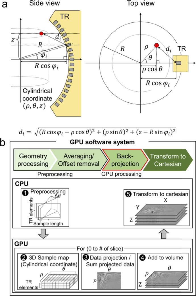
Post-image processing and reconstruction are performed with a personal computer (i7-4790 CPU, Intel, USA; GTX-960 GPU, Nvidia, USA). To reconstruct a 3D volumetric XACT image from raw data, we developed a GPU-accelerated image reconstruction software based on the back-projection algorithm (Fig. 2(a)). The volume size of the reconstructed XACT image is 40 mm × 40 mm × 40 mm in the X, Y, and Z axes, respectively, and the voxel size is 0.1 mm. The GPU software projects the detected XA data in cylindrical coordinates (θ, ρ, z) to reconstruct one 3D volumetric XACT image. Using arrival times of the detected XA signal, we can project the scanned data into the imaging volume by calculating the distance between the image voxel and the US transducer element location. As shown in Fig. 2(a), the distance between the imaged voxel (θ, ρ, z) and the ith US transducer element di is
| (3) |
where R is the radius of the arc-shaped US array transducer and is the ith transducer element’s angle.
Fig. 2.
. (a) Reconstruction geometry. R, radius of the arc-shaped US array transducer; , ith transducer element’s angle. (b) Pipeline of the custom-developed graphics processing unit (GPU) software. TR, transducer.
During the image reconstruction, the coordinates for image reconstruction and the transducer element positions are calculated and the raw data is preprocessed (e.g., by averaging and data offset removal) before the GPU computation (Fig. 2(b1)). Then the data is uploaded into the GPU memory. For the back-projection process, we make three kernels that can be computed in parallel: (1) a sample map kernel, (2) a data kernel made by projecting the sample and summing all the elements, and (3) a kernel containing slice data added to the volume data. The sample map kernel initializes the sample map (θ, ρ, transducer elements), which gives the distance (di) between the image voxel in cylindrical coordinates and the position of the ith transducer element (Fig. 2(b2)). Then we project all the imaging frame data into cylindrical coordinates according to the sample map. The initially mapped data is the data from each transducer element projected onto the cylindrical coordinates. Therefore, we sum all the data from all the transducer elements that contribute one tomographic slice image (θ, ρ) (Fig. 2(b3)). We repeat the process for every tomographic slice and store the tomographic slice data in the cylindrical volume (θ, ρ, z) (Fig. 2(b4)). After the back-projection process, we copy the back-projected data to the CPU memory and convert the data to Cartesian coordinates (x, y, z) (Fig. 2(b5)).
3. Results and discussion
3.1. X-ray induced acoustic characteristics of target materials
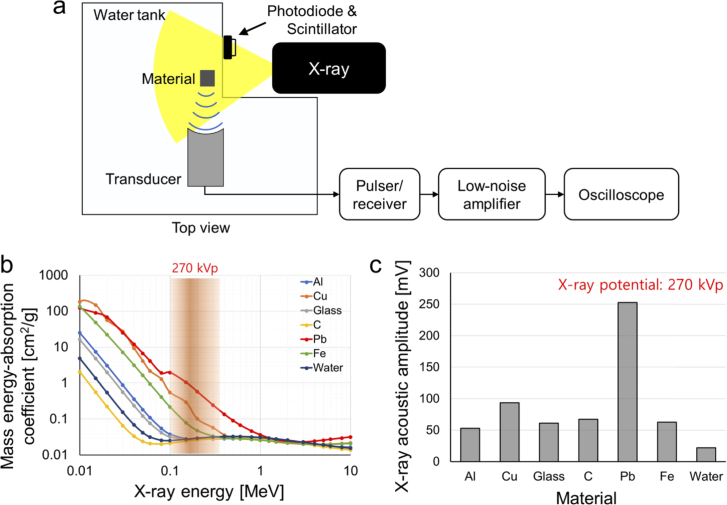
To verify the feasibility of X-ray induced acoustic signal generation and detection of our novel system, we prepared aluminum, copper, glass, graphite, lead, and steel elongated blocks measuring 4 mm × 4 mm × 40 mm (X, Y, and Z axes, respectively), which are potential candidates that could be developed as contrast agents. To minimize X-ray absorption by water, the blocks were placed near the wall of the custom-made (acryl) water tank. To analyze XA signals generated from various material, a focused single element transducer with a central frequency of 0.5 MHz, a fractional bandwidth (-6 dB) of 50%, and a focal length of 1 inch was used (Fig. 3(a)). The main reason is that it was much easier and more precise to position the target materials at the same location using the focused single-element transducer. A pulser/receiver (5072PR, Olympus NDT, USA) with a gain of 50 dB and a low-noise amplifier (SR560, Stanford Research Systems, USA) with a gain of 40 dB were utilized to amplify the generated XA signals. The detected XA signals were recorded with an oscilloscope (MSO5204, Tektronix, USA), and the signal was averaged 99 times to enhance the SNR.
Fig. 3.
(a) Schematic of X-ray induced acoustic (XA) signal generation and detection. (b) Mass energy absorption coefficients of Al, aluminum; Cu, copper; glass; C, graphite; Pb, lead; and Fe, steel. (c) Measured XA amplitude at 270 kVp.
The initial pressure rise, p0, can be expressed as follows [30]:
| (4) |
where the Γ is the Gruneisen parameter, ηth is the heat conversion efficiency, μa is the X-ray absorption coefficient (cm-1), and F is the X-ray fluence (J/cm2). Several studies investigated the Gruneisen parameters of materials, and method to measure Gruneisen parameters. For example, the Gruneisen parameter of lead, copper, and steel are 2.1, 2.0, and 1.7, respectively [31–33]. The generated XA signal is proportional to the X-ray absorption coefficient. The mass energy absorption values for the above-mentioned materials are shown in Fig. 3(b). At a 270 kVp X-ray potential, lead has the highest mass energy absorption coefficient, copper has the second highest, and those of the remaining materials are negligible in comparison. The mass energy absorption coefficient of lead is almost two to three times higher than that of copper in the ∼270 keV energy range. The acquired XA signals from all the tested materials are shown in Fig. 3(c). The strongest XA signal was detected from lead, followed by copper. The XA signal from lead is 2.5 times stronger than that of copper, matching well with the known mass energy absorption coefficient. Additionally, the XA signal from aluminum, glass, carbon, and steel is 2.4, 2.6, 3.0, and 2.8 times stronger than water which is used for the US coupling medium.
3.2. Comparison of the execution times of the back-projection algorithm
We compared the execution times of the back-projection algorithms in three systems: the CPU software in MATLab (MathWorks, USA) [34], a custom-made CPU software in C++, and a custom-made GPU software (Table 1). The data size was 3072 × 96 × 180 (sample length, number of transducer elements, and imaging frames, respectively) in the floating-point data type (4 byte) after averaging. The execution times of the CPU and GPU software were compared by reconstructing 3D XACT images with various fields of view and voxel sizes. Of the two CPU software, the C++ software was 3.1 to 3.5 times faster than the MATLab software. After accelerating the software with GPU parallel computing, the software becomes 41.2 to 43.3 times faster than that of the MATLab software and 12.2 to 13.2 times faster than that of the C++ software.
Table 1. Comparison of the execution times of the back-projection algorithm.
| Slice size | CPU (i7-4790) MATLab [sec] | CPU (i7-4790) C++ [sec] | GPU (GTX-960) [sec] |
|---|---|---|---|
| 301 × 301 | 44.4 | 13.6 | 1.0 |
| 401 × 401 | 79.0 | 25.1 | 1.9 |
| 601 × 601 | 181.8 | 52.9 | 4.2 |
| 801 × 801 | 338.6 | 95.4 | 7.8 |
Data size: 3072 × 96 × 180 (Sample length × transducer elements × the number of frames). Listed execution time is for one slice image.
3.3. 3D volumetric X-ray induced computed tomography imaging
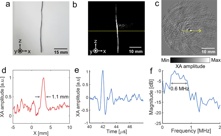
For 3D volumetric XACT imaging, we imaged a 40 mm long lead target with a thickness of 1 mm and a width of 1 mm (Fig. 4(a)). The lead target was suspended under the piezo motor and rotated 360° for whole volume scanning. Then we reconstructed the 3D volumetric XACT image with a field of view of 40 mm × 40 mm × 40 mm (X, Y, and Z axis, respectively) and a step size of 0.1 mm, using the GPU software. The 3D volumetric XACT image and the movie were captured with lab-made 3D volume visualization software. The acquired 3D volumetric XACT image (Fig. 4(b) and Visualization 1 (2MB, avi) ) and the cross-sectional XACT image in the X-Y plane (Fig. 4(c)) at the yellow dashed line region in Fig. 4(b) clearly show the lead target’s original shape. There was no additional process to remove the XA signal from water during the 3D volumetric XACT image reconstruction. As seen in the XA amplitude profile (Fig. 4(d)), at the yellow dashed line in the 2D cross-sectional image (Fig. 4(c)), the width of the lead target measures 1.1 mm, which is a close match to its original thickness. The signal profile along time and response spectra of the detected XA signal from lead is shown in Fig. 4(e and f). The measured – 6 dB bandwidth is 0.6 MHz, which is similar to the bandwidth of the 96-element arc-shaped US array transducer (617 kHz). Then we measured signal to noise ratio (SNR) of the acquired 3D volumetric XACT image. The SNR is calculated as the amplitude value of lead region divided by the standard deviation of lead region. The measured SNR is 3.2.
Fig. 4.
3D volumetric X-ray induced acoustic computed tomography (XACT) of an elongated lead target. (a) Photograph. (b) 3D volumetric XACT image (Visualization 1 (2MB, avi) ). (c) Cross-sectional XACT image (X-Y plane). (d) XA amplitude profile acquired along the yellow dashed line in c. (e) XA amplitude profile along time. (f) Spectrum of the XA signal.
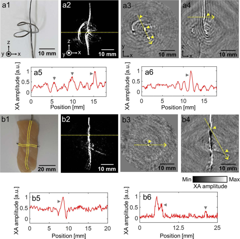
We next prepared a complexly shaped ribbon lead target (Fig. 5(a1)) for 3D XACT imaging, and hung it under the piezo motor. The reconstructed 3D volume images clearly show the original complex shape of the imaged target (Fig. 5(a2) and Visualization 2 (2.7MB, avi) ). Figures 5(a3 and a4) show 2D cross-sectional images of the target in the X-Y and X-Z planes, respectively. In the 2D cross-sectional images, we extracted XA amplitude profiles from the target area (Fig. 5(a5) and (a6)) along the yellow dashed line and marked each peak point in the 2D cross-sectional images and XA amplitude profiles. Then we embedded two lead targets in a cross shape in chicken tissue and hung the long vertical part under the piezo motor to acquire 3D volumetric XACT images (Fig. 5(b1)). The lead targets embedded in the chicken tissue are visualized in the 3D XACT images (Fig. 5(b2) and Visualization 3 (3MB, avi) ). The 2D cross-sectional images in X-Y planes and X-Z planes are shown in Figs. 5(b3) and (b4) and the XA amplitude profiles at the yellow dashed line in 2D cross-sectional images are shown in Figs. 5(b5) and (b6), respectively. The XA signals from the horizontally placed part at the ribbon-shaped lead target (First peak in Fig. 5(a5)) is lower than that of the vertically placed part (Second and third peaks in Fig. 5(a5)). Additionally, as shown in the acquired XACT images and the XA amplitude profiles, the XA signals from the horizontally embedded lead target (Second peak in Fig. 5(b6)) is lower than that of the vertically embedded lead target (Peak in Fig. 5(b5) and first peak in Fig. 5(b6)). This difference of the XA amplitude was due to the acoustic signal propagation direction and the US transducer geometry. During rotational scanning of the sample, the horizontally oriented sample meets the arc-shaped US array transducer orthogonally. Thus, the array transducer can detect only the XA signals from the very close part, according to the direction of the XA signal propagation, and not the rest of the horizontally placed part. Therefore, the XA signals from the horizontally placed portion in the ribbon-shaped and the cross-shaped lead targets are relatively low.
Fig. 5.
3D volumetric X-ray induced acoustic computed tomography of a ribbon-shaped lead sample and a cross-shaped lead targets in chicken tissues. (a1 and b1) Photograph of the lead targets. (a2 and b2) Reconstructed 3D volumetric XACT images (Visualization 2 (2.7MB, avi) and Visualization 3 (3MB, avi) ). Cross-sectional XACT images in (a3 and b3) X-Y and (a4 and b4) X-Z planes. (a5 and b5) XA amplitude profile acquired along the yellow dashed line in a3 and b3. (a6 and b6) XA amplitude profile acquired along the yellow dashed line in a4 and b4.
4. Discussion and conclusions
In this study, we developed a novel 3D volumetric XACT system with a pulsed X-ray source, a 96-element arc-shaped US array transducer, and a piezo rotation motor. The XA signal generation and detection was verified with various materials, and it was found that the XA signal was proportional to the mass energy absorption coefficient. The developed system provided 3D volumetric XACT images by rotating the imaged target along the azimuth axis of the arc-shaped US array transducer. The curvature of the arc-shaped ultrasound array transducer used in our experiments is 65 mm optimized for the FOV of 40 mm × 40 mm × 40 mm (X, Y, and Z axis, respectively), which is mainly suitable for imaging small animals. A large curvature, long transducer length, and pitch size are required for clinical translation. For example, a photoacoustic mammoscope was developed using twelve of 32-element arc-shaped US array transducer with the radius of curvature of 120 mm and the pitch size of 1.4 mm [35]. Additionally, as the pulse width of the X-ray source increases, the high frequency component of the XA signal tends to decrease, and the frequency response and potential spatial resolution of XA imaging are directly dependent on the X-ray pulse width and the frequency response of the US transducer, the X-ray pulse width and the frequency response of the US transducer can be optimized according to desired image resolution and application. With the 3D volumetric XACT system, we successfully obtained 3D volumetric XACT images of different shapes of lead targets in water and of lead targets embedded in chicken tissue. Further, we accelerated the XACT image reconstruction with GPU processing. With the custom developed GPU software, the reconstruction time was up to 43.3 times faster than with the CPU-MATLab software.
For the future clinical translation, the X-ray acoustic signals of bone and X-ray contrast media, including iodine-based angioplasty contrast agents and barium-based gastrointestinal contrast agents, can be analyzed using X-ray source energy in KeV region similar to the CT scanner. Additionally, the X-ray energy of MeV region used for radiotherapy can be used for a radiotherapy dosimeter as the generated XA signal is linearly related to the amount of exposed radiation dose [36]. The developed 3D XACT system can be a potential tool for monitoring X-ray dose distribution inside biological tissues, and it can also be applied to a variety of disease studies, including radiation therapy monitoring, drug delivery, and molecular imaging.
Funding
MSIT (Ministry of Science, ICT and Future Planning10.13039/501100003621), Republic of Korea, under the ICT Consilience Creative program (IITP-2019-2011-1-00783) supervised by the IITP (Institute for Information and Communications Technology Planning and Evaluation); The Pioneer Research Center Program through the National Research Foundation of Korea10.13039/501100003725, funded by the Ministry of Science and ICT (NRF-2017M3C1A3037762, 2015M3C1A3056407); The POSCO Green Science Project funded by POSCO (Pohang Iron @ Steel Co, Ltd), Republic of Korea.
Disclosures
The authors declare no competing financial interests.
References
- 1.Hickling S., Léger P., El Naqa I., “On the detectability of acoustic waves induced following irradiation by a radiotherapy linear accelerator,” IEEE Trans. Sonics Ultrason. 63(5), 683–690 (2016). 10.1109/TUFFC.2016.2528960 [DOI] [PubMed] [Google Scholar]
- 2.Mascarenhas S., Vargas H., Cesar C., “A photoacoustical radiation dosimeter,” Med. Phys. 11(1), 73–74 (1984). 10.1118/1.595456 [DOI] [PubMed] [Google Scholar]
- 3.Tang S., Yang K., Chen Y., Xiang L., “X-ray-induced acoustic computed tomography for 3D breast imaging: A simulation study,” Med. Phys. 45, 1662–1672 (2018). 10.1002/mp.12829 [DOI] [PubMed] [Google Scholar]
- 4.Xiang L., Tang S., Ahmad M., Xing L., “High resolution X-ray-induced acoustic tomography,” Sci. Rep. 6(1), 26118 (2016). 10.1038/srep26118 [DOI] [PMC free article] [PubMed] [Google Scholar]
- 5.Choi W., Park E.-Y., Jeon S., Kim C., “Clinical photoacoustic imaging platforms,” Biomed. Eng. Lett. 8(2), 139–155 (2018). 10.1007/s13534-018-0062-7 [DOI] [PMC free article] [PubMed] [Google Scholar]
- 6.Lee C., Kim J., Zhang Y., Jeon M., Liu C., Song L., Lovell J. F., Kim C., “Dual-color photoacoustic lymph node imaging using nanoformulated naphthalocyanines,” Biomaterials 73, 142–148 (2015). 10.1016/j.biomaterials.2015.09.023 [DOI] [PubMed] [Google Scholar]
- 7.Upputuri P. K., Pramanik M., “Fast photoacoustic imaging systems using pulsed laser diodes: a review,” Biomed. Eng. Lett. 8(2), 167–181 (2018). 10.1007/s13534-018-0060-9 [DOI] [PMC free article] [PubMed] [Google Scholar]
- 8.Lee D., Beack S., Yoo J., Kim S. K., Lee C., Kwon W., Hahn S. K., Kim C., “In Vivo Photoacoustic Imaging of Livers Using Biodegradable Hyaluronic Acid-Conjugated Silica Nanoparticles,” Adv. Funct. Mater. 28, 1800941 (2018). 10.1002/adfm.201800941 [DOI] [Google Scholar]
- 9.Kim C., Chen Z., Multimodal Photoacoustic Imaging: Systems, Applications, and Agents (Springer, 2018). [DOI] [PMC free article] [PubMed] [Google Scholar]
- 10.Xia J., Kim C., Lovell J. F., “Opportunities for photoacoustic-guided drug delivery,” Curr. Drug Targets 16(6), 571–581 (2015). 10.2174/1389450116666150707100328 [DOI] [PMC free article] [PubMed] [Google Scholar]
- 11.Kellnberger S., Soliman D., Tserevelakis G. J., Seeger M., Yang H., Karlas A., Prade L., Omar M., Ntziachristos V., “Optoacoustic microscopy at multiple discrete frequencies,” Light: Sci. Appl. 7(1), 109 (2018). 10.1038/s41377-018-0101-2 [DOI] [PMC free article] [PubMed] [Google Scholar]
- 12.Steinberg I., Huland D. M., Vermesh O., Frostig H. E., Tummers W. S., Gambhir S. S., “Photoacoustic clinical imaging,” Photoacoustics 14, 77–98 (2019) 10.1016/j.pacs.2019.05.001. [DOI] [PMC free article] [PubMed] [Google Scholar]
- 13.Liu W., Yao J., “Photoacoustic microscopy: principles and biomedical applications,” Biomed. Eng. Lett. 8(2), 203–213 (2018). 10.1007/s13534-018-0067-2 [DOI] [PMC free article] [PubMed] [Google Scholar]
- 14.Liu W., Shcherbakova D. M., Kurupassery N., Li Y., Zhou Q., Verkhusha V. V., Yao J., “Quad-mode functional and molecular photoacoustic microscopy,” Sci. Rep. 8(1), 11123 (2018). 10.1038/s41598-018-29249-1 [DOI] [PMC free article] [PubMed] [Google Scholar]
- 15.Jeon S., Park E.-Y., Choi W., Managuli R., jong Lee K., Kim C., “Real-time delay-multiply-and-sum beamforming with coherence factor for in vivo clinical photoacoustic imaging of humans,” Photoacoustics 15, 100136 (2019). 10.1016/j.pacs.2019.100136 [DOI] [PMC free article] [PubMed] [Google Scholar]
- 16.Park B., Lee H., Jeon S., Ahn J., Kim H. H., Kim C., “Reflection-mode switchable subwavelength Bessel-beam and Gaussian-beam photoacoustic microscopy in vivo,” J. Biophotonics 12, e201800215 (2019). 10.1002/jbio.201800215 [DOI] [PubMed] [Google Scholar]
- 17.Jeon S., Kim J., Lee D., Woo B. J., Kim C., “Review on practical photoacoustic microscopy,” Photoacoustics 15, 100141 (2019). 10.1016/j.pacs.2019.100141 [DOI] [PMC free article] [PubMed] [Google Scholar]
- 18.Chen M., Knox H. J., Tang Y., Liu W., Nie L., Chan J., Yao J., “Simultaneous photoacoustic imaging of intravascular and tissue oxygenation,” Opt. Lett. 44(15), 3773–3776 (2019). 10.1364/OL.44.003773 [DOI] [PMC free article] [PubMed] [Google Scholar]
- 19.Kim J., Kim J. Y., Jeon S., Baik J. W., Cho S. H., Kim C., “Super-resolution localization photoacoustic microscopy using intrinsic red blood cells as contrast absorbers,” Light: Sci. Appl. 8(1), 103 (2019). 10.1038/s41377-019-0220-4 [DOI] [PMC free article] [PubMed] [Google Scholar]
- 20.Moradi F., Khandaker M. U., Alrefae T., Ramazanian H., Bradley D., “Monte Carlo simulations and analysis of transmitted gamma ray spectra through various tissue phantoms,” Appl. Radiat. Isot. 146, 120–126 (2019). 10.1016/j.apradiso.2019.01.031 [DOI] [PubMed] [Google Scholar]
- 21.Lei H., Zhang W., Oraiqat I., Liu Z., Ni J., Wang X., El Naqa I., “Toward in vivo dosimetry in external beam radiotherapy using x-ray acoustic computed tomography: A soft-tissue phantom study validation,” Med. Phys. 45, 4191–4200 (2018). 10.1002/mp.13070 [DOI] [PubMed] [Google Scholar]
- 22.Tang S., Ramseyer C., Samant P., Xiang L., “X-ray-induced acoustic computed tomography of concrete infrastructure,” Appl. Phys. Lett. 112(6), 063504 (2018). 10.1063/1.5009936 [DOI] [Google Scholar]
- 23.Kruger R. A., Liu P., Fang Y. R., Appledorn C. R., “Photoacoustic ultrasound (PAUS)—reconstruction tomography,” Med. Phys. 22(10), 1605–1609 (1995). 10.1118/1.597429 [DOI] [PubMed] [Google Scholar]
- 24.Köstli K. P., Frenz M., Weber H. P., Paltauf G., Schmidt-Kloiber H., “Optoacoustic tomography: time-gated measurement of pressure distributions and image reconstruction,” Appl. Opt. 40(22), 3800–3809 (2001). 10.1364/AO.40.003800 [DOI] [PubMed] [Google Scholar]
- 25.Hickling S., Hobson M., El Naqa I., “Feasibility of x-ray acoustic computed tomography as a tool for noninvasive volumetric in vivo dosimetry,” Int. J. Radiat. Oncol., Biol., Phys. 90, S843 (2014). 10.1016/j.ijrobp.2014.05.2417 [DOI] [Google Scholar]
- 26.Kim J., Park E.-Y., Jung Y., Kim B. C., Kim J. H., Yi C.-Y., Kim I. J., Kim C., “X-ray acoustic-based dosimetry using a focused ultrasound transducer and a medical linear accelerator,” IEEE Trans. Radiat. Plasma Med. Sci. 1(6), 534–540 (2017). 10.1109/TRPMS.2017.2757484 [DOI] [Google Scholar]
- 27.Xiang L., Han B., Carpenter C., Pratx G., Kuang Y., Xing L., “X-ray acoustic computed tomography with pulsed x-ray beam from a medical linear accelerator,” Med. Phys. 40(1), 010701 (2012). 10.1118/1.4771935 [DOI] [PMC free article] [PubMed] [Google Scholar]
- 28.Tang S., Nguyen D., Zarafshani A., Ramseyer C., Zheng B., Liu H., Xiang L., “X-ray-induced acoustic computed tomography with an ultrasound transducer ring-array,” Appl. Phys. Lett. 110(10), 103504 (2017). 10.1063/1.4978049 [DOI] [Google Scholar]
- 29.Xu M., Wang L. V., “Universal back-projection algorithm for photoacoustic computed tomography,” Phys. Rev. E 71(1), 016706 (2005). 10.1103/PhysRevE.71.016706 [DOI] [PubMed] [Google Scholar]
- 30.Yao J., Ke H., Tai S., Zhou Y., Wang L. V., “Absolute photoacoustic thermometry in deep tissue,” Opt. Lett. 38(24), 5228–5231 (2013). 10.1364/OL.38.005228 [DOI] [PMC free article] [PubMed] [Google Scholar]
- 31.Joshi R., Bhatt N., Thakore B., Vyas P., Jani A., “Grüneisen parameter and equations of states for cospper–High pressure study,” Computational Condensed Matter 15, 79–84 (2018). 10.1016/j.cocom.2017.11.003 [DOI] [Google Scholar]
- 32.Huang D., Liu X., Su L., Shao C., Jia R., Hong S., “Measuring Grüneisen parameter of iron and copper by an improved high pressure-jump method,” J. Phys. D: Appl. Phys. 40(17), 5327–5330 (2007). 10.1088/0022-3727/40/17/047 [DOI] [Google Scholar]
- 33.Petrova E., Ermilov S., Su R., Nadvoretskiy V., Conjusteau A., Oraevsky A., “Using optoacoustic imaging for measuring the temperature dependence of Grüneisen parameter in optically absorbing solutions,” Opt. Express 21(21), 25077–25090 (2013). 10.1364/OE.21.025077 [DOI] [PMC free article] [PubMed] [Google Scholar]
- 34.Brecht H.-P. F., Su R., Fronheiser M. P., Ermilov S. A., Conjusteau A., Oraevsky A. A., “Whole-body three-dimensional optoacoustic tomography system for small animals,” J. Biomed. Opt. 14(6), 064007 (2009). 10.1117/1.3259361 [DOI] [PMC free article] [PubMed] [Google Scholar]
- 35.Schoustra S. M., Piras D., Huijink R., Op’t Root T. J., Alink L., Kobold W. M., Steenbergen W., Manohar S., “Twente Photoacoustic Mammoscope 2: system overview and three-dimensional vascular network images in healthy breasts,” J. Biomed. Opt. 24(12), 1 (2019). 10.1117/1.JBO.24.12.121909 [DOI] [PMC free article] [PubMed] [Google Scholar]
- 36.Hickling S., Lei H., Hobson M., Léger P., Wang X., El Naqa I., “Experimental evaluation of x-ray acoustic computed tomography for radiotherapy dosimetry applications,” Med. Phys. 44(2), 608–617 (2017). 10.1002/mp.12039 [DOI] [PubMed] [Google Scholar]


