Abstract
Computed tomography (CT) plays a key role in the peri-procedural planning of left atrial appendage occlusion (LAAO) device placement and post-procedural evaluation. The geometric variability of the interatrial septum, left atrium, and the left atrial appendage morphology can be fully visualized and intuitively appreciated through CT-derived, patient-specific 3D model unique to each individual’s anatomy. This review further defines the strengths and limitations of CT peri-procedural imaging in the planning of LAAO.
Keywords: Left atrial appendage occlusion, computerized tomography, WATCHMAN™ device, 3D modeling, artifact, 3D transesophageal echocardiogram
Introduction
Atrial fibrillation (AF) is the most prevalent cause of cardiac arrhythmias in the elderly, affecting approximately 9% of adults over the age of 80 (1). Notably, non-valvular AF is associated with a 5-fold increase in ischemic stroke risk (2). The left atrial appendage (LAA) is an important anatomical structure in the pathophysiology of AF-related cerebrovascular events. An embryological remnant; the LAA is a slightly flattened tubular sac found in the muscular wall of the left atrium. Interest in mechanical exclusion of the appendage has risen in recent years due to the primacy of LAA thrombus as the cause of thromboembolic events in debilitating strokes (3).
Traditionally, stroke prevention in high-risk non-valvular AF patients, defined by CHADS2 ≥1 or CHADS-VASc ≥2 (4), leads to prescription of long-term oral anticoagulants (OAC). However, up to 50% of patients with AF are ineligible for OAC therapy, due to occupational hazards, lifestyle limitations, or history of bleeding (5). In 2009, the PROTECT-AF study demonstrated the WATCHMAN™ LAA occlusion (LAAO) device with a tapering OAC strategy was noninferior to traditional long-term OAC therapy (6). The WATCHMAN™ device is a commercially available LAAO device that prevents large thrombi from exiting the LAA and to occlude the LAA so that thrombi do not form within it; thereby preventing cerebrovascular events (Figure 1). This LAAO approach has demonstrated equivalent reduction in stroke and mortality compared to warfarin in the AF patient population (7,8). However, there exists an early-operator learning curve to understanding the imaging behind successful LAA planning.
Figure 1.
The commercially available sizes of WATCHMAN™ left atrial appendage (LAA) occluder devices. (A) shows a 33 mm WATCHMAN™ device; (B) a 30 mm device; (C) a 27 mm device; (D) a 24 mm device; (E) a 21 mm device.
This review outlines use of CT based procedural planning for LAAO; focusing on the peri and intraprocedural protocols for LAA imaging.
The procedure
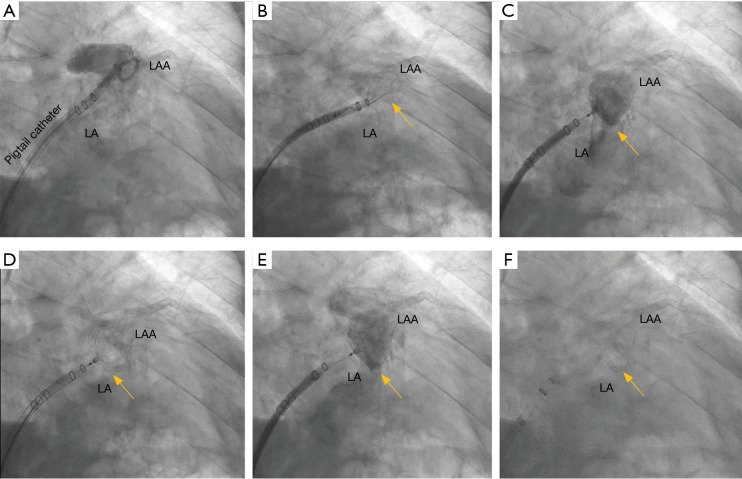
Imaging for LAA requires in depth understanding of the key procedural steps, device nuances, and catheter shapes in anticipation of LAAO. At the start of the LAAO procedure, femoral venous access is obtained followed by trans-septal puncture. After entry is obtained into the left atrium, a wire is advanced into the left superior pulmonary vein over which the WATCHMAN™ access sheath is advanced. The wire is then removed, and an angled graduated pigtail catheter is introduced into the LAA to allow for contrast visualization of the LAA on fluoroscopy. The WATCHMAN™ access sheath is then advanced into the LAA until the appropriate device marker band is aligned with the ostial plane as identified by fluoroscopy. The pigtail is then removed, and the WATCHMAN™ delivery catheter is advanced through the WATCHMAN™ access sheath until the distal marker bands are aligned via TEE guidance. The Watchman™ device is then deployed using a passive exposure method in which the operator retracts the WATCHMAN™ access sheath/delivery catheter combination while stabilizing the deployment knob (Figure 2).
Figure 2.
Fluoroscopic images of WATCHMAN™ device being implanted into the ostium of the left atrial appendage (LAA) with delivery system and access sheath. The yellow arrow shows device face in landing zone of LAA. In (A), the LAA shows anterior chicken wing anatomy, pigtail catheter advanced through WATCHMAN™ access sheath in the appendage, contrast filling anatomy of the appendage. In (B), WATCHMAN™ device catheter is advanced through the WATCHMAN™ access sheath, device deployment is in process with feet exposed and flowering. In (C), WATCHMAN™ device deployed in the appendage. In (D), a fully expanded WATCHMAN™ device silhouette can be seen in landing zone of the LAA. In (E), contrast is injected through the WATCHMAN™ device. In (F), device is released from a device catheter, and the implant is complete.
Once deployed, the device is interrogated utilizing transesophageal echocardiogragraphy (TEE) and contrast fluoroscopy to determine whether it meets the position, anchor, size, and seal (PASS) criteria. Ideal landing zone of the device is defined at the level of the circumflex artery with minimal protrusion of the device into the left atrium. The LAAO device should be sufficiently anchored as evidenced by no movement of the device position when the deployment knob is pulled. Device compression should be a minimum of 8% (10% for the FLX device) and peri-device flow should measure no more than 5mm at vena contracta on 2D TEE color flow.
Up until 2011, 2D TEE has been the primary imaging modality guiding LAAO (9). With the advent of transcatheter aortic valve replacement therapies, CT has become the standard of care for transcatheter device planning. In pre-LAAO imaging, CT-based, pre-procedure LAA assessment predicts device size more accurately and thereby decreases LAAO-related complications (10). Post-procedure CT is also standard practice to assess patients for a range of complications, including device thrombosis, peri-WATCHMAN leaks and their mechanisms, pericardial effusions, and any shifts in device position.
Role of CT imaging in left atrial appendage occlusion
Role of CT in pre-LAAO planning
CT image acquisition and image processing tools
Pre-procedural imaging is obtained using a retrospectively ECG-gated CT scan of the chest. When performed on a Siemens Somatom Force scanner (Siemens Medical Solutions US, Malvern, PA), tube voltage and current are adapted to the patient’s body size and helical pitch to the patient’s heart rate at the time of the scan. A total of 66 mL of iodinated contrast, Isovue 370 (Bracco Diagnostics, Patheon Italia, Ferentino, Italy), is administered via an 18-gauge peripheral intravenous line. An initial bolus tracking scan of a single slice through the left atrium is used to initiate main acquisition once a density threshold of 100 HU is reached within a region of interest (ROI) placed inside the left atrium. The imaged volume begins at the level of the carina and extends caudally through the most inferior margin of the heart. Upon scan completion and subsequent reconstruction of image data across multiple cardiac phases (cine series), images are transferred in DICOM (Digital Imaging and Communications in Medicine) format from the scanner to a dedicated server for further processing and evaluation. Analysis is performed on the reconstructed cine series of the acquired CT with the Vitrea (Vital Images, Minnetonka, MN) and Mimics (Materialise, Leuven Belgium) software platforms.
Image analysis
First-pass image processing analysis: anatomic eligibility for LAAO therapies
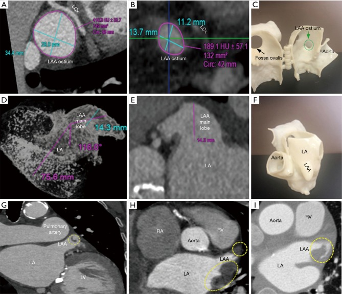
The initial evaluation of the preprocedural CT scan is to determine patient eligibility for LAAO. Not all patients have an LAA either due to congenital absence or prior surgical/catheter interventions; the details of which may have been lost in the medical record (Figure 3). Those who do possess an LAA may still not be anatomically eligible for LAAO due to existing devices or may require deferral of procedure due to presence of LAA thrombus (Figure 4). Patients with active LAA thrombus confirmed by delayed imaging CT, are placed on six weeks of anticoagulation therapy and followed with repeat imaging to evaluate for clearing. Patients with history of LAA intervention, i.e., surgical ligation or clip of the LAA are not optimal candidates for LAAO therapies due to anatomical limitations and fall out of the scope of this article.
Figure 3.
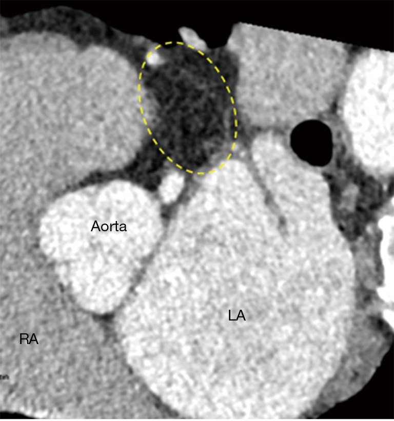
Surgically ligated left atrial appendage (LAA) seen on pre-LAAO CT. Yellow dotted circle shows the absence of contrast uptake in an area where the main lobe of the LAA existed prior to surgical intervention.
Figure 4.
Depictions of different scenarios in which a pre-LAAO CT scan can rule out occlusion. In (A), a CT scan revealed that the ostium is too big to fit even the largest size of available WATCHMAN™ devices. In (B), a CT scan showed that the ostium is too small to fit even the smallest size of available WATCHMAN™ devices. In (C), the small size of ostium shown in image (B) visualized on 3D print highlighted in green dotted line. In (D,E), CT scans revealed that the length of the LAA is too small to fit even the smallest size of available WATCHMAN™ devices. In (F), the small length of the same LAA is shown in images (D) and (E) visualized on 3D print. In (G-I), LAA clots found on pre-LAAO CT scan are shown within yellow dotted line with Image (H) also depicting an LA clot.
Second pass analysis: LAA landing zone sizing
The LAA is analyzed on multi-planar cross-sectional views reconstructed at 10% R-R intervals across the entire cardiac cycle, and LAA motion and contractility are evaluated. The LAA device landing zone is identified at maximal LAA diastole or mid to late left ventricular systole. This phase corresponds to maximum LAA end-diastolic filling, when the LAA is largest, and therefore to the ideal phase for device sizing to minimize the occurrence of device under-sizing and subsequent peri-device leaks, and embolization risk. The LAA landing zone is defined as the region between the main lobe of the LAA and the course of the left circumflex artery. Maximal device landing zone dimensions are obtained utilizing cross-sectional multiplanar reconstruction (MPR) planes optimized to the main lobe of the LAA just distal to the orifice. This landing zone is where a LAAO device will ideally seat within the confines of the LAA (10).
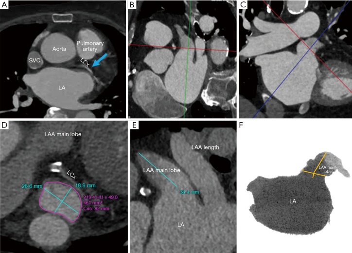
To visualize the landing zone, the takeoff of the proximal left circumflex artery from the left anterior descending artery is identified using the axial view port. The coronal and sagittal crosshairs are then rotated to run parallel to the main LAA lobe to ensure optimal visualization of the landing zone. Using the measuring tools on post-processing software, values are assigned to the maximum and minimum diameter, area, and circumference of the landing zone in an axial viewport. In the sagittal and coronal views, the length of the LAA from landing zone to distal tip is measured (10). The widest diameter is used to determine device size, per WATCHMAN™ sizing instructions (11). The length of the chosen device dictates the depth necessary for device deployment. This length is drawn from the centroid of the LAA ostium oriented towards the distal tip of the main lobe. An inverted maximal-intensity projection with this line and the 3D crosshairs overlay, showing both the ostium and device surface as a single 2D plane, is used to simulate the LAA intraprocedural angiogram (Figure 5). This process allows implanters to anticipate the necessary C-arm angles, depth of deployment, and optimal catheter tip positioning minimizing empirical optimization in the lab reducing procedure time, and operator exposure to ionizing radiation (10).
Figure 5.
Step by step processing of pre-procedural CT images to determine maximum diameter, minimum diameter, and circumference of the left atrial appendage (LAA) ostium as well as the length of the LAA on post-processing software. (A) Step 1: blue arrow indicating the takeoff of the proximal left circumflex artery from the left anterior descending artery is identified using the axial view. (B,C) Step 2: LAA orifice can be identified by the plane connecting the pulmonary vein ridge superiorly to the inferior junction of the left atrium and the LAA at the level of the left circumflex coronary artery. (B) shows the landing zone from a sagittal view, and (C) from a coronal view. (D,E) Step 3: (D) shows the maximum and minimum diameter (shown by turquoise lines), area, and circumference (shown by magenta encircling) of the landing zone in an axial viewport. In (E), the length of the LAA from landing zone to distal tip is measured and shown by turquoise line. (F) Step 4: An inverted maximal-intensity projection in which the length is drawn from the center of the LAA ostium oriented towards the distal tip of the main lobe shown by yellow lines. This shows is used to simulate the LAA intraprocedural angiogram.
Final step: catheter selection for LAA device delivery
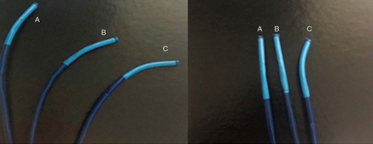
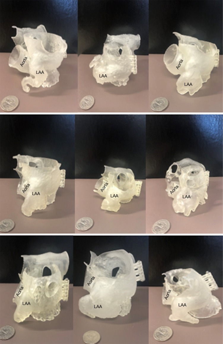
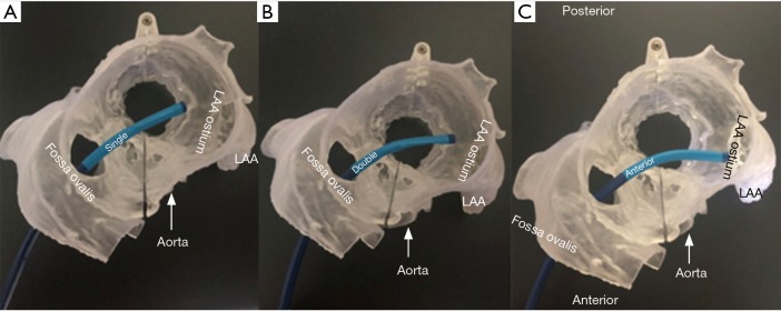
The final step in the preparation for occlusion is to determine the curve configuration of the catheter used for deployment: single curve, double curve, or anterior curve sheaths are available for the WATCHMAN™ device (Figure 6). 3D-printed models of the patient’s heart are generated using the aforementioned CT data set (Figure 7). To build these models, CT images of the phase corresponding to maximal end-diastolic filling of the LAA are exported to specialized Mimics software (Materialise, Leuven, Belgium). Blood volume of the left atrium, LAA, aortic annulus, and the most proximal portions of the superior and inferior vena cava are subsequently segmented. Then, computer aided design (CAD) work is performed to create a 3D model using a Stratasys Objet 30Pro printer (Stratasys, Minneapolis, MN) printer. Upon completion of the 3D print, physical catheters are then applied to the patient-specific 3D model to determine the LAA catheter that best conforms to the angulation of the patient’s LAA main lobe landing zone (Figure 8). Much is written about the need for an inferior posterior transseptal puncture for LAAO, but it is clear that the optimal final catheter orientation should be coplanar with the axis of the main lobe of the LAA (Figure 8). This may not be achieved by a regimented site of transseptal puncture. By selective image processing, it is possible to artificially drop out the entire secundum septum, and, therefore, determine not only the ideal delivery catheter for the LAA but also the optimal site at which that catheter should cross the septum. In the context of expert teaching and training centers, this aids appropriate case selection since more forgiving anatomies can be pre-selected for less experienced operators.
Figure 6.
Single, double, and anterior configuration of catheters used to implant WATCHMAN™ device in landing zone. Catheters labeled A show a single configuration, B shows double, and C shows anterior.
Figure 7.
Diversity of shapes and sizes of the left atrial appendage (LAA) shown by 3D models. These are 3D prints modeled 1:1 after patient anatomy as part of the pre-procedural case planning. Quarter for scale.
Figure 8.
Catheter configurations used to implant WATCHMAN™ device. Single, double, and anterior configuration of catheters used to implant WATCHMAN™ device by being thread through the fossa ovalis through the left atrium to the ostium of the left atrial appendage (LAA). The single configuration is shown in (A), the double in (B), the anterior in (C).
Role of CT in post-LAAO closure evaluation
Presence or absence of LAAO
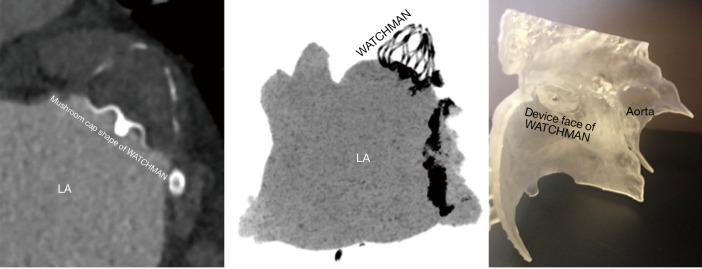
Forty-five days after device implantation, CT imaging is repeated to check for correct placement of the device and to detect any peri-WATCHMAN leaks. A similar analysis to the preprocedural protocol is performed on Vitrea to visualize the LAA. On post-LAA CT images, the WATCHMAN™ device can be identified by its unique mushroom cap-like appearance (Figure 9). Incomplete occlusion can be inferred from an incomplete opacification of contrast filling between the device and the distal LAA (Figure 10). Complete occlusion occurs when there is absence of contrast in the LAA distal to the LAAO device (Figure 11).
Figure 9.
Successful left atrial appendage (LAA) occlusion by WATCHMAN™ seen on a 45-day post-LAA occlusion CT scan. A CT image of the completely sealed LAA with a view of the mushroom cap shape of the WATCHMAN™ is seen in A. The successful occlusion can also be seen in (B) as inverted maximum intensity projection (MIP) image and (C) as a 3D model with WATCHMAN™ device of same size.
Figure 10.
Peri-WATCHMAN™ leak seen on post left atrial appendage (LAA) occlusion CT showing incomplete occlusion. In (A), the leak was measured in an axial view to be at 9.0 mm by 6.5 mm in diameter. The leak can also be identified by yellow bar in inverted maximum intensity projection (MIP) image in (B) and coronal view in (C).
Figure 11.
Comparison of sealed and unsealed LAA anatomy after LAAO. In (A), a post LAA CT scan showed an uncompressed unsealed 33 mm WATCHMAN™ device (compression of 6.45%). In (B), a post-LAA CT scan shows a successful occlusion with a 27 mm WATCHMAN™ device (compression of 12.97%). There is an 8% compression minimum recommended to meet position, anchor, size, and seal (PASS) criteria.
Device sizing
Post-LAAO CT can be used to identify stability of device anchoring and device compression. Maximal and minimal diameters, perimeter and area can be obtained utilizing multi-planar reconstruction to evaluate if a device has reached optimal compression standards (Figure 11).
Device stability
Post-procedural CT can also be used to asses for device migration or embolization. Recent data shows that WATCHMAN™ device embolization is 0.24% ranging on a severity spectrum (12). In the worst-case scenario, embolization of the occluder can be life-threatening, as seen in the case reported by Stollberger et al. in which the device migrated to the left ventricular outflow tract and obliterated the aortic cusps (13). As other case reports have shown, device embolization may be asymptomatic, if dislodged into the left atrium or embolized to the aorta in a different location (14,15). Retrieval methods for the mobilized device are presently not standardized and must vary to account for the location of the embolized occluder, the patient’s hemodynamic status, and the experience of the implanter.
CT scan quality control: troubleshooting
Common CT analysis errors in pre and post-measurement
CT analysis errors that can lead to complications during LAAO are both scanner-related and patient-related.
Scanner-related quality troubleshooting
Heart rate control
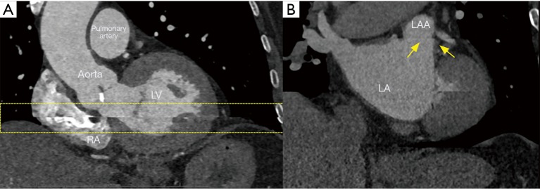
Stable and slower heart rates are critically important to image quality in LAA CT acquisitions. Patients should be encouraged to take their cardiac medications prior to CT scan arrival. In the setting of erratic heart rates, which is commonly associated with AF patients, additional rate-controlling agents may need to be administered for image quality optimization. Post-scan acquisition, electrocardiographic (EKG) editing can be performed on scans where misregistration artifacts may appear due to cardiac ectopy (16) (Figure 12).
Figure 12.
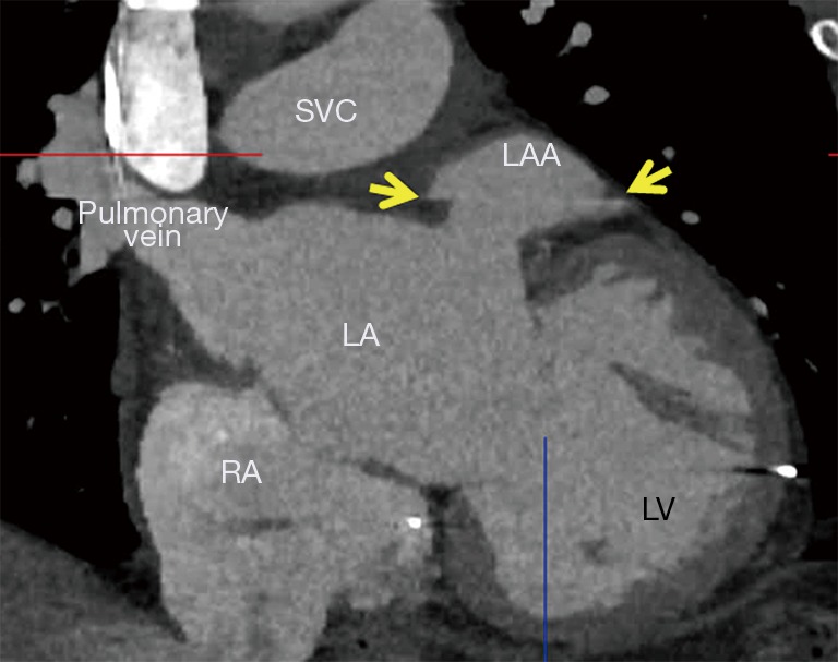
Heart rate motion artifact. Artifacts caused by inconsistency in heart motion from beat to beat (yellow arrows). When overlying on the left atrial appendage (LAA), the cardiac structure of interest, this artifact poses great challenges in correct sizing of the planned device.
Contrast injection
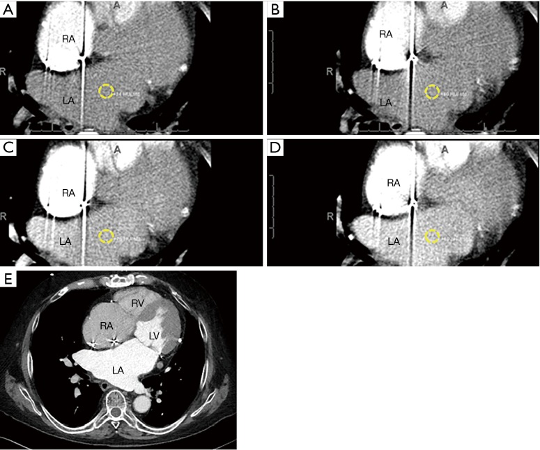
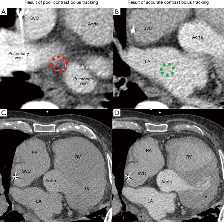
Intravenous contrast bolus tracking is used in all current clinical scanners to optimize image timing to synchronize the scan with the peak enhancement of the cardiac structures of interest (17). However, bolus tracking is not always sufficiently accurate, and in these cases, images may be taken prematurely or much delayed relative to the peak enhancement. This will lead to images with poor contrast enhancement, and heart anatomy will thus be more difficult to distinguish. In the setting of LAAO CT, the best practice should be to place the ROI for bolus tracking at the center of the left atrium (Figure 13). ROI placed too close to the posterior wall of the left atrium may result in wash out of the contrast in the left atrium, and opacification of incorrect cardiac chambers (Figure 14).
Figure 13.
Contrast arrival in the left atrial (LA) with a properly placed region of interest (ROI). (A)-(D) show a time-lapse of gradual opacification of the LA with an ROI location, highlighted in yellow dotted ring, at the centroid of the left atrium. An optimally enhanced left atrium for pre-left atrial appendage occlusion (LAAO) planning is seen in (E) as a result of this properly placed ROI.
Figure 14.
Artifact seen due to poor bolus tracking by scanner. Due to improper region of interest (ROI) placement at the level of the pulmonary veins, highlighted in red dotted encircling, on baseline scan setup seen in (A), CT images at the level of are poorly enhanced at the level of the left atrial appendage (LAA) and aorta seen in (C). This can be compared to the enhanced left atrium and aorta seen in (D) due to the well-performed bolus tracking seen in (B), highlighted in green dotted encircling, on the same patient. There is a notable difference in the enhancement of the left atrium as well as the left ventricle.
Patient-specific quality control
Patient movement and active breathing during cardiac scanning severely limits scan usability since the resultant artifacts cannot be corrected via post-processing. Motion results in blurred images as well as long streaks (Figure 15). Motion-related artifacts are most commonly attributed to breathing during the scan and bulk movement from flinches caused by the sensation of contrast dye injection, as many patients report feeling warm and flushed on injection with a temporary metallic taste in the mouth. Motion artifacts can be minimized by a faster scanner simply because the patient has less time to move during the acquisition (16). Additional breathing and scan simulation and patient education performed by highly trained CT technologists can help minimize patient-specific factors that negatively impact image quality. Additional breath and scan simulation patient education training performed by highly trained CT technologists can help minimize patient-induced scan quality difficulties.
Figure 15.
Patient motion artifact. In (A), a CT motion artifact, highlighted between yellow dashed lines, can be seen due to a patient taking a breath during the time of scan acquisition. Ideally these CT images are expected to be free of breathing motion. The yellow arrow shows the mismatch of ribs in this study indicating chest wall motion caused by patient’s breathing during the scan process. In (B), the same type of breathing artifact, indicated by yellow arrows, passes through the left atrial appendage (LAA) near where the landing zone could fall making accurate sizing challenging.
Technically challenging body habitus
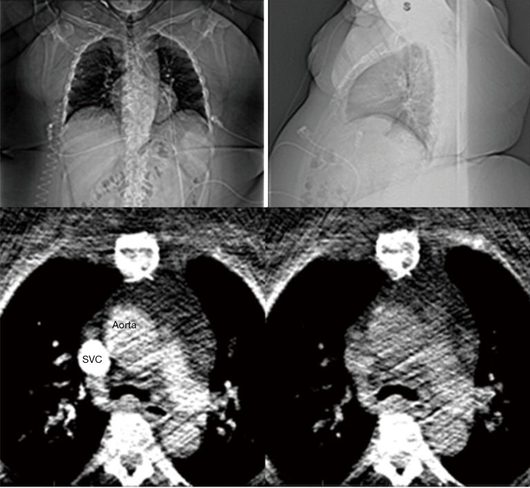
With an increasing body mass index and epidemic of metabolic syndrome amongst the general population (17), quality CT imaging in patients with elevated body mass is technically challenging. Large patient body habitus greatly reduces X-rays reaching the detector due to increased absorption by tissue, leading to substantial increase in noise and streaking artifacts on CT images (Figure 16). Thus, steps should be taken to ensure adequate image quality before scanning patients with higher BMIs. Noise can be reduced very effectively by taping the breasts and abdominal fat away from the field of view of a chest CT scan. Additionally, the injection rate and the volume of the iodinate contrast can be adapted to the patient’s body habitus in order to achieve adequate opacification of the cardiac structures of interest. Acquisition based imaging using CT scanners equipped with bariatric tables improves patient care and image optimization for larger patients. These scanners typically have a higher table load limit, a larger gantry aperture, a larger scan field of view, more powerful X-ray generators and X-ray tubes, and other features, to produce more reliable CT studies for these patients (18).
Figure 16.
Effects of large body habitus on CT scan quality. There is a grainy quality to the CT images acquired from a patient with a high BMI.
Application of CT in real-world clinical practice
EKG-gated multi-slice CT imaging gives a more comprehensive and accurate assessment of cardiac structures compared to traditional 2D TEE and 3D TEE imaging. Wang et al previously demonstrated case planning with CT versus 2D and 3D TEE yields LAA size estimates that differ to the extent that alternative WATCHMAN™ device sizes would be chosen for the identical case (10). The LAA is sensitive to adequate preload due to its inherent anatomical location as an accessory structure and off-shoot of the left atrium. The last structure to be filled off the left atrium, the LAA is underinflated with dehydration. TEE imaging greatly undersizes the true dimensions of the LAA due to inherent procedural rules of peri-procedural fasting states prior to TEE probe insertion; thereby diminishing patient’s hydration status. Difficulties in under-sizing LAA landing zones are related to deployment of undersized devices which leads to increased likelihood of peri-device leaks and device embolization. Additionally, patients with small LAAs may be inappropriately excluded from occlusion if TEE alone is used to estimate LAA landing zone size.
Future roles of CT in LAA planning: 3D printing
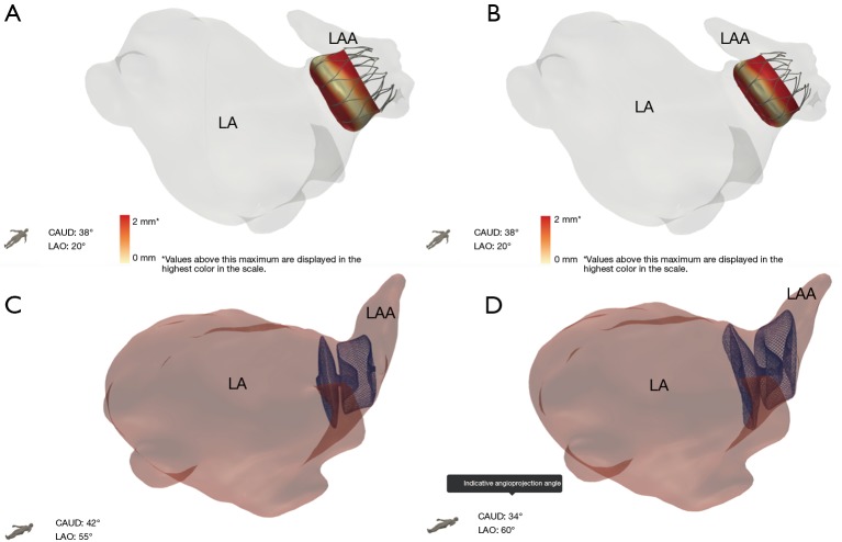
The morphology of the LAA is highly diverse among patients, and can vary in number of lobes, orientation, width, and length. The ostium of the LAA can have a spherical shape in some patients or an ellipsoid shape in others. Thus, 3D printing technology offers an important advantage in LAAO planning by allowing implanters to physically fit devices and catheters in an individual’s LAA carefully considering curvatures that could make catheter navigation difficult and LAA pedunculations that would prevent proper seal of the device. Moreover, 3D printing allows physicians to visualize the fossa ovalis, the usual site of transseptal puncture. During CAD work, fossae are hollowed so changes in size and location in the septum can be visualized on 3D models, and catheters can be threaded through. For patients with a history of patent foramen ovale who have septal occluders, using the 3D model allows implanters to determine if puncturing the occluder itself or at a new septal pierce point would minimize damage to the septum but still allow successful device deployment. New sophisticated software with machine learning algorithms to select best implant device size and location is also being explored (Figure 17). These advances allow CT imaging data to show how devices will interact with unique patient anatomy in attempt to predict clinical outcome.
Figure 17.
CT-based software algorithms from FeOps demonstrating potential opportunities to attempt prediction of device interaction with left atrial appendage (LAA) anatomy. (A) shows greater apposition of a WATCHMAN™ 27 mm device compared to a (B) 24 mm device; and (C) shows inadequate apposition and too proximal position of a 25 mm Amulet device, compared to (D) which shows greater apposition with a 31 mm Amulet device that is placed more distally.
Conclusions
The LAA is the main source of stroke-causing thrombus and is more often fatal and disabling in patients with AF. Presently, in the United States, the WATCHMAN™ LAA occluder device is an effective alternative to treatment with OAC. CT paired with a 3D-printed heart model allows implanters to determine an optimal plan of action for LAAO based on specific patient anatomy. The role of CT in LAAO is important to patient device selection, patient device delivery system selection, and long-term patient device follow-up. With the evolution of CT imaging capabilities, the role of CT in LAAO will continue to advance as novel therapies arrive to the market.
Acknowledgments
The authors thank Sarah Whitehouse, Senior Medical Writer at Henry Ford Hospital Main Campus, for editing this review. The authors thank Jillian Haio for manuscript figure editing support.
Ethical Statement: The authors are accountable for all aspects of the work in ensuring that questions related to the accuracy or integrity of any part of the work are appropriately investigated and resolved.
Footnotes
Conflicts of Interest: Dr. Wang is a consultant for Boston Scientific and receives research grant funding assigned to employer HFHS from Boston Scientific. Dr. O’Neill has served as a consultant for Edwards Lifesciences, Medtronic, Boston Scientific, Abbott Vascular and St. Jude Medical; and serves on the Board of Directors of Neovasc Inc. Dr Daniels is a consultant for WL Gore. Dr. Saw is a proctor, consultant and has received research grants from Boston Scientific and Abbott Vascular; and is on advisory boards for FEops, Baylis, Abiomed, Bayer, AstraZeneca, and Gore. Sanel Kesinovic and Tony Lamorgese are employees of Boston Scientific. All other authors report no relevant financial disclosures.
References
- 1.Go AS, Hylek EM, Phillips KA, et al. Prevalence of diagnosed atrial fibrillation in adults: national implications for rhythm management and stroke prevention: the Anticoagulation and Risk Factors in Atrial Fibrillation (ATRIA) study. JAMA 2001;285:2370-5. 10.1001/jama.285.18.2370 [DOI] [PubMed] [Google Scholar]
- 2.Reiffel JA. Atrial fibrillation and stroke: epidemiology. Am J Med 2014;127:e15-6. [DOI] [PubMed] [Google Scholar]
- 3.Saxena R, Lewis S, Berge E, et al. Risk of early death and recurrent stroke and effect of heparin in 3169 patients with acute ischemic stroke and atrial fibrillation in the International Stroke Trial. Stroke 2001;32:2333-7. 10.1161/hs1001.097093 [DOI] [PubMed] [Google Scholar]
- 4.January CT, Wann S, Alpert JS, et al. 2014 AHA/ACC/HRS guideline for the management of patients with atrial fibrillation: A report of the American College of Cardiology/American Heart Association Task Force on Practice Guidelines and the Heart Rhythm Society. Circulation 2014;130:2071-104. 10.1161/CIR.0000000000000040 [DOI] [PubMed] [Google Scholar]
- 5.del Conde I, Halperin JL. Ineligibility for anticoagulation in patients with atrial fibrillation. Am J Med 2013;126:105-11. 10.1016/j.amjmed.2012.07.001 [DOI] [PubMed] [Google Scholar]
- 6.Reddy VY, Sievert H, Halperin J, et al. Percutaneous left atrial appendage closure vs warfarin for atrial fibrillation: A randomized clinical trial. JAMA 2014;312:1988-98. 10.1001/jama.2014.15192 [DOI] [PubMed] [Google Scholar]
- 7.Chanda A, Reilly JP. Left atrial appendage occlusion for stroke prevention. Prog Cardiovasc Dis 2017;59:626-35. 10.1016/j.pcad.2017.04.003 [DOI] [PubMed] [Google Scholar]
- 8.Safavi-Naeini P, Rasekh A. Closure of left atrial appendage to prevent stroke: Devices and status. Tex Heart Inst J 2018;45:172-4. 10.14503/THIJ-18-6693 [DOI] [PMC free article] [PubMed] [Google Scholar]
- 9.Lockwood SM, Alison JF, Obeyesekere MN, et al. Imaging the left atrial appendage prior to, during, and after occlusion. JACC Cardiovasc Imaging 2011;4:303-6. 10.1016/j.jcmg.2010.09.024 [DOI] [PubMed] [Google Scholar]
- 10.Wang DD, Eng M, Kupsky D, et al. Application of 3-dimensional computed tomographic image guidance to WATCHMAN implantation and impact on early operator learning curve: Single-center experience. JACC Cardiovasc Interv 2016;9:2329-40. 10.1016/j.jcin.2016.07.038 [DOI] [PubMed] [Google Scholar]
- 11.Vainrib AF, Harb SC, Jaber W, et al. Left atrial appendage occlusion/exclusion: Procedural image guidance with transesophageal echocardiography. J Am Soc Echocardiogr 2018;31:454-74. 10.1016/j.echo.2017.09.014 [DOI] [PubMed] [Google Scholar]
- 12.Reddy VY, Gibson DN, Kar S, et al. Post- Approval U.S. experience with left atrial appendage closure for stroke prevention in atrial fibrillation. J Am Coll Cardiol 2017;69:253-61. 10.1016/j.jacc.2016.10.010 [DOI] [PubMed] [Google Scholar]
- 13.Stöllberger C, Schneider B, Finsterer J. Serious complications from dislocation of a Watchman left atrial appendage occluder. J Cardiovasc Electrophysiol 2007;18:880-1. 10.1111/j.1540-8167.2007.00784.x [DOI] [PubMed] [Google Scholar]
- 14.Pisani P, Sanderlli L, Fabbrocini M, et al. Left-atrial-appendage occluder migrates in an asymptomatic patient. Tex Heart Inst J 2014;41:443-4. 10.14503/THIJ-13-3173 [DOI] [PMC free article] [PubMed] [Google Scholar]
- 15.Takayuki G, Grimmig O, Soren J, et al. Asymptomatic dislocation of a Watchman left atrial appendage occluder. Asian Cardiovasc Thorac Ann 2019;27:394-5. 10.1177/0218492318805620 [DOI] [PubMed] [Google Scholar]
- 16.Boas EF, Fleischmann D. CT artifacts: Causes and reduction techniques. Imaging Med 2012;4:229-40. 10.2217/iim.12.13 [DOI] [Google Scholar]
- 17.Yanovski SZ, Yanovski JA. Obesity prevalence in the United States--up, down or sideways? New Engl J Med 2011:364:987-9. 10.1056/NEJMp1009229 [DOI] [PMC free article] [PubMed] [Google Scholar]
- 18.Modica MJ, Kanal KM, Gunn ML. The obese emergency patient: imaging challenges and solutions. Radiographics 2011;31:811-23. 10.1148/rg.313105138 [DOI] [PubMed] [Google Scholar]


