Although most physicians are aware of the harmful effects of ionizing radiation, reviewing some concepts of radiation safety is helpful.
Regarding cancer risk, we think in terms of a linear no-threshold model; that is, there is a no-threshold dose for increased risk, and the risk increases linearly. This makes sense because any ionizing radiation damages DNA. Repair is by imperfect mechanisms, leading to mutations and increased risks of cancer. The obvious conclusion in this model is that no radiation dose is safe, which has led to the Nuclear Regulatory Commission's concept of ALARA (as low as reasonably achievable).
We also know that the field of electrophysiology has been dominated by the use of fluoroscopy. Investigators1 from Italy, who recently compiled data from 2010 through 2016 on more than 8,000 procedures, reported that electrophysiologic ablation procedures expose staff and patients to substantial levels of radiation: the lowest level was about 1 mSv on average for electrophysiologic ablation, and the highest was 28 mSv for ventricular tachycardia ablation. In comparison, the average person is exposed to 2.4 mSv in background radiation yearly, and 20 mSv is the annual limit for nuclear industry workers. These numbers decreased as newer equipment was used, but they are still alarming.
Interventionalists have disproportionately developed left-sided head and neck tumors because that side is usually closer to the radiation source, resulting in an effective dose of radiation nearly twice that on the right. In one series,2 85% of brain tumors were left-sided in a disease that is classically distributed equally in each hemisphere. Understanding the importance of these findings is difficult because extensive data have not been collected; regardless, the higher effective dose on the left side of the brain is concerning.
In addition, observational data indicate that wearing protective lead causes a variety of musculoskeletal issues. In one study,3 questionnaire data revealed that 30% of lead-wearing interventionalists reported spinal problems less than 10 years out of fellowship, and more than 60% of laboratory staff had long-term musculoskeletal pain. These problems substantiate the need for the ALARA regulatory policy.
We are finally at the time when “reasonably achievable” includes “zero,” largely because of the rapid development of electroanatomic mapping systems, which can reliably reveal complex cardiac anatomy and display catheter position in real time. As this technology has progressed, treatment of cardiac arrhythmias has shifted to ablation procedures, which can be done without sacrificing safety or efficiency.
In a single-center experience, Razminia and colleagues4 performed 500 consecutive ablation procedures without fluoroscopy over 5 years. Their safety results often outperformed historical safety numbers (overall complication rate, 1%). Recurrence rates were also in line with those suggesting no compromise in efficacy.
Di Biase and colleagues5 specifically focused on pulmonary vein (PV) isolation for atrial fibrillation without fluoroscopy. Their data indicated good success and safety rates, with no significant difference between nonfluoroscopic and conventional ablation time (average, ~2 hr).
Electrophysiologists at the Texas Heart Institute have been using minimal fluoroscopic techniques for some time. In 2017, we instituted a reproducible nonfluoroscopic protocol and have had great success with it. The chief obstacle to overcome involved the right-sided regions that have historically necessitated fluoroscopy to ensure venous access and sheath position, to advance equipment into the superior vena cava (SVC), and to perform the transseptal puncture.
Many institutions are doing nonfluoroscopic ablation procedures with EnSite™ technology (St. Jude Medical, part of Abbott), and we have had good results in limited experience with the system. However, our institution typically uses the Carto® electroanatomic mapping platform (Biosense Webster, a Johnson & Johnson company) for nonfluoroscopic ablations.
The Carto Procedure
To obtain femoral venous access, we use a vascular ultrasound probe oriented perpendicular to the long axis of the vessels, to distinguish the femoral artery from the vein. After the J wire is inserted into the common femoral vein, the probe is reoriented to a horizontal view to confirm that the wire is entirely within the vessel. This enables the operator to avoid fluoroscopy entirely when evaluating wire position.
When the venous access sheaths are in place, the first catheter that we advance is an intracardiac echocardiographic (ICE) catheter (probe) through the venous route to the heart, which enables us to evaluate the approach and to assign landmarks for positioning mapping catheters later. Of note, the ICE catheter is stiff; an 8F SoundStar® catheter (Biosense Webster) can puncture the vein.
Advancing the ICE catheter perpendicular to the direction of the transmitted fan beam is crucial; then, as the catheter is advanced farther, the anticipated position of the catheter tip will be immediately to the right of the probe. To ensure that the catheter advances freely, it should be rotated to keep the lumen open to the right of the probe.
After the ICE probe is properly positioned in the right atrium (RA), sound contours can be obtained on the Carto system, which helps with orienting the mapping catheter and establishing the geometry of the left atrium (LA).
We initially orient ourselves with the ICE probe positioned in the mid RA (“home view”), for viewing the RA, tricuspid valve, ventricular inflow and outflow tracts, and centrally positioned aortic root. A sound contour is taken of the aortic valve. From this anteriorly directed view, a series of clockwise rotations of the probe reveals other important anatomy. First, the posterior structures are seen, including the coronary sinus (CS) ostium (view needed for CS cannula placement) and the fossa ovalis (FO) (view needed for transseptal puncture). Next, the LA and other left-sided structures are revealed. The LA appendage (LAA), on the lateral side of the LA, can be distinguished from the left upper PV on the basis of other anterior structures in view, particularly the mitral valve. After that, the left-sided PVs immediately posterior to the LAA are seen. Finally, the beam fans across the posterior wall to the right-sided PVs. A sound contour is taken of all these structures for relative anatomic positioning. We generally trace our contours synchronized with the T wave on electrocardiography, which enables standardized positioning during ventricular diastole. Then, we generally focus on better defining the LAA and coumadin ridge (if present), which is accomplished by maneuvering the probe into the right ventricle (RV).
On return to home view, the ICE catheter is anteroflexed toward the RV and rotated counterclockwise to move the probe off the septum and into the center of the tricuspid annulus. The tricuspid valve must be open before the catheter is advanced. When the catheter is advanced past the tricuspid valve into the RV, the anteroflexion is released to a neutral position, and the catheter is rotated clockwise to obtain the aortic valve short-axis view. In this position, a coumadin ridge is highly echogenic, separating the anterior LAA from the left upper PV. Such contouring helps to guide editing of the geometric shell because the ridge can distort during anatomic mapping on the PV and LAA side.
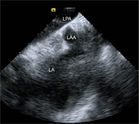
We then get a complete view of the LAA, by placing the ICE catheter in the left pulmonary artery (PA). We accomplish this by returning to the aortic valve short-axis view within the RV, then retroflexing the catheter by rotating it clockwise into the RV outflow tract. After the catheter has been passed through the pulmonic valve and into the right PA, it can be angled inferiorly to reveal the distal tip of the LAA and confirm absence of thrombus (Fig. 1).
Fig. 1.

Intracardiac echocardiogram shows the distal left atrial appendage (LAA) from the left pulmonary artery (LPA).
LA = left atrium
After acquiring all the left-sided contours, we advance a DecaNav® CS catheter (Biosense Webster) into the RA and begin to define its geometry by creating a reference matrix. The DecaNav is a navigation-enabled catheter with a magnetic component and an indifferent electrode that serves as a unipolar electrode alternative to the Wilson central terminal.
To create the matrix, the DecaNav catheter is advanced under electroanatomic mapping guidance into the SVC. With a gentle deflection, the catheter is pulled slowly with a rotating motion to define the border walls of the RA. From here, the RA cavity is “painted” with the catheter, filling empty space with shell, thus enabling nonnavigational mapping catheters to be seen as they move within the matrix. After matrix acquisition, the catheter is positioned in the CS with use of the previously obtained sound contour, to assist with CS cannulation.
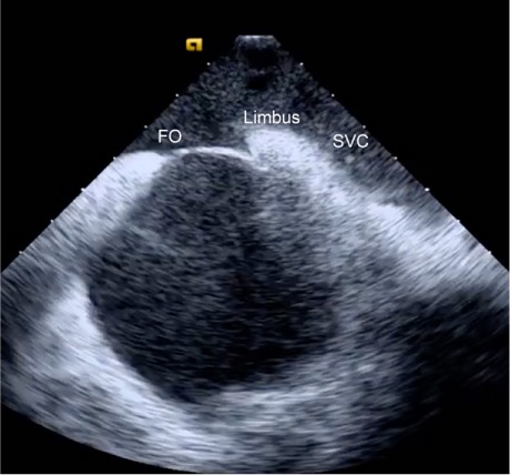
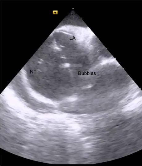
Next is the transseptal puncture, for which good-quality ICE views are crucial. From the home view, the catheter is rotated clockwise until the FO is visible. Simultaneous posteroflexion and rightward deflection directs the fan beam superiorly to display the SVC, the limbus, and the FO (Fig. 2), enabling the operator to advance the J wire and transseptal sheath safely into the SVC. The sheath can usually be viewed directly as it is advanced, but detecting the loss of intense metallic echodensity as the sheath covers the wire is often easier. After the transseptal sheath and needle are attached to a manifold capable of saline flush and transduction, they are slowly retracted, with the transseptal needle oriented toward the 5 o'clock position. The previously mentioned SVC view enables visualization of the sheath as it advances from the SVC, to the limbus, and then to the FO. After the needle is positioned anteriorly and inferiorly on the FO, it is exposed while the sheath remains steady. The needle should always be visible to ensure its safe position. After the needle position has been confirmed, the system is advanced en bloc with use of gentle forward pressure. The operator should feel the pressure suddenly release as the needle “pops” across the FO. After LA pressures are recorded, we typically use forward saline flush on the manifold to better see the tip of the needle (Fig. 3). The system is rotated counterclockwise to the 3 o'clock position to maximize distance from the lateral LA wall during advancement. After the system has been positioned safely in the mid LA, it should be held in place while being covered by the dilator and sheath. The dilator is then separated from the sheath, and the sheath is advanced until ICE confirmation that it has crossed the FO. From this point, the procedure is standard because most operators can navigate the LA without using fluoroscopy. By the time the first mapping catheter enters the LA, the major landmark structures have been defined by sound contours.
Fig. 2.

Intracardiac echocardiogram of the superior vena cava (SVC) from the right atrium reveals the SVC, limbus, and fossa ovalis (FO) in a single plane.
Fig. 3.

Intracardiac echocardiogram shows the transseptal needle tip (NT) as it is advanced during migration across the fossa ovalis into the left atrial (LA) cavity. The highly echodense NT is highlighted by a flow of saline flush.
We apply similar principles to treat not only atrial fibrillation and flutter, but also ventricular tachycardia and premature ventricular contractions.
When a zero-fluoroscopy ablation protocol is initiated, operators may need to overcome their initial feelings of being out of their comfort zone as they learn the new workflow. The pressure to maintain high procedural volumes, especially in private practice, can also be discouraging; however, after they become comfortable with nonfluoroscopic ablation, the complexity of operations and procedural times are not substantially different from those with fluoroscopy.
In summary, we are satisfied that zero-fluoroscopy ablations can be performed without compromising safety, effectiveness, or productivity. As zero-fluoroscopic approaches are refined and applied to other electrophysiologic procedures, we hope that the risk of exposing staff and patients to ionizing radiation can be further reduced and eventually eliminated.
References
- 1.Casella M, Della Russo A, Russo E, Catto V, Pizzamiglio F, Zucchetti M J Am Heart Assoc [Internet] 11. Vol. 7. American Heart Association; 2019. X ray exposure in cardiac electrophysiology: a retrospective analysis in 8150 patients over 7 years of activity in a modern, large-volume laboratory. e008233. Available from: [DOI] [PMC free article] [PubMed] [Google Scholar]
- 2.Roguin A, Goldstein J, Bar O, Goldstein JA. Brain and neck tumors among physicians performing interventional procedures. Am J Cardiol. 2013;111(9):1368–72. doi: 10.1016/j.amjcard.2012.12.060. [DOI] [PubMed] [Google Scholar]
- 3.Orme NM, Rihal CS, Gulati R, Holmes DR, Jr, Lennon RJ, Lewis BR et al. Occupational health hazards of working in the interventional laboratory: a multisite case control study of physicians and allied staff. J Am Coll Cardiol. 2015;65(8):820–6. doi: 10.1016/j.jacc.2014.11.056. [DOI] [PubMed] [Google Scholar]
- 4.Razminia M, Willoughby MC, Demo H, Keshmiri H, Wang T, D'Silva OJ et al. Fluoroless catheter ablation of cardiac arrhythmias: a 5-year experience. Pacing Clin Electrophysiol. 2017;40(4):425–33. doi: 10.1111/pace.13038. [DOI] [PubMed] [Google Scholar]
- 5.Di Biase L, Horton R, Trivedi C, Mohanty P, Mohanty S, Bai R et al. Abstract 16237: Zero fluoroscopy ablation of atrial fibrillation: a safety and feasibility study [Internet] Circulation. 2014;130(Suppl 2) A16237. Available from: https://www.ahajournals.org/doi/abs/10.1161/circ.130.suppl_2.16237. [Google Scholar]


