Abstract
Analytic fits to the recommended electron-impact excitation and ionization cross sections for Be I are presented. The lowest 19 terms of configurations 2snl (n ≤ 4) and 2p2 terms below the first ionization limit are considered. The fits are based on the accurate calculations with the convergent close coupling (CCC) method as well as the B-spline R-matrix (BSR) approach. The fitted cross sections provide rate coefficients that are believed to approximate the original data within 10% with very few exceptions. The oscillator strengths for the dipole-allowed transitions between all the considered states are calculated with the relativistic multi-configuration Dirac–Hartree–Fock (MCDHF) approach and compared with the CCC and BSR results. This comparison shows a very good agreement except for a handful of cases with likely strong cancellations.
1. Introduction
Beryllium is proposed as the main plasma-facing material for the first wall of the international tokamak ITER [1] due to its unique physical properties such as low radiative power losses, low plasma contamination, and low fuel retention. Understanding of erosion and degradation of the first wall is a crucial issue for productive and safe operation of the tokamak [2]. Beryllium atoms sputtered from the wall will be transported into the main plasma volume, which would affect the control and confinement of the plasma. Some experience on the beryllium migration has been gained though the Joint European Torus (JET) ITER-like plasma wall experiment [3–5]. The beryllium migration can be interpreted through spectroscopic measurements from the plasma. Accurate atomic data are the prime requirement to interpret such measurements [6]. Among the various atomic processes, electron-impact excitation and ionization are the dominant processes occurring in such plasmas and affecting the emission.
Due to the significance of accurate electron-impact collisional data for Be, the objective of the present work is to evaluate the status of electron-impact excitation and ionization data for Be and to generate the recommended datasets for use in analysis of Be I spectra. Neutral beryllium has four electrons in two closed shells 1s and 2s in its ground state. Owing to its simple structure as compared to many complex atoms, various powerful computational methods, such as R-matrix with pseudostates (RMPS) [7,8], time-dependent close coupling (TDCC) [9], convergent close-coupling (CCC) [10–12], B-spline R-matrix (BSR) [12], and a complex optical potential method [13] have been used to calculate electron collisional data for Be. Recently, complete and consistent data on electron-impact collisions were reported by Zatsarinny et al. [12] using BSR and CCC. The cross sections for electron collisions with Be were reported for the energy range from the threshold to 100 eV. Electron-impact excitation and ionization cross sections obtained from these methods generally are in very good agreement for most datasets, including the intensities and positions of resonances. Both methods have been successfully applied to many atomic systems for a long time now, and the agreement between their results also supports the reliability of the cross sections. Therefore, we have utilized those datasets to derive recommended cross sections and provide analytic fits.
In this work, we consider electron-impact excitations between the lowest 19 terms, viz., 2s2 1S, 2s2p 3P and 1P, 2p2 1D and 3P, 2s3l 3L and 1L (L = 0–2), and 2s4l 3L and 1L (L = 0–3). Throughout the paper we use the short notation n2S+1L for 2snl 2S+1L terms, and P1D and P3P for 2p2 1D and 3P, respectively. In addition, we have also calculated the oscillator strengths between all the considered states for dipole-allowed transitions in the relativistic multi-configuration Dirac–Hartree–Fock (MCDHF) approach using the GRASP2K code [14]. The calculated oscillator strengths are compared with the BSR [12] and CCC [12] results, as well as with the recommended values from the Atomic Spectra Database of the National Institute of Standards and Technology (NIST) [15].
2. Computational details
2.1. GRASP2K
The Dirac–Coulomb Hamiltonian for relativistic calculations of N-electron system is given by
| (1) |
Where and β are the Dirac matrices, and represent the position coordinate and momentum operator of the ith electron respectively, is the central potential due to electron–nucleus interaction, and is the inter-electronic distance. The atomic state wave function (ASF) can be expanded as a linear combination of configuration state functions (CSFs) as:
| (2) |
Here NCSF is the number of CSFs used to represent the wave function. Only those CSFs will contribute that have the same parity and total angular momentum (J) as the ASF. A CSF can be constructed from the antisymmetric sums of products of N one-electron Dirac spinors (i.e., Slater determinants) and determined with the self-consistent field approach. The bi in Eq. (2) are the mixing coefficients and can be obtained by diagonalizing the Hamiltonian HDC.
In this work, an extended optimal level (EOL) mode has been used to compute the wave functions of many states of the same parity simultaneously, which gives a balanced description of atomic states with an accurate energy spacing. For even-parity configurations 1s22s2 (1S) and 1s22p2 (1D, 3P) as well as odd-parity configurations 1s22s2p (3P, 1P), core correlations are the most important [16,17]. Therefore, separate calculations have been carried out for the transition rates between 1s22l2l′ configurations. For these calculations, the CSF expansions have been obtained by single (S), double (D) and triple (T) excitations from the occupied orbitals to principal quantum number n ≤ 3 and SD excitations up to n ≤ 8 and maximum orbital angular momentum lmax = 6. The excitation of one of the 1s electrons is restricted to the n ≤ 2 shell accounting for core–core correlations while the other three electrons can be excited up to the largest principal quantum number n = 8. The other configurations considered here involve single excitation of the 2s electron to states with n≤4, viz., 1s22s3s, 1s22s3p, 1s22s3d, 1s22s4s, 1s22s4p, 1s22s4d, and 1s22s4f. The maximum principal quantum number for the reference configurations is n = 4. For the MCDHF calculations, the active space is expanded by considering SDT excitations from the reference configurations to n ≤ 4, SD excitations up to n = 8 and lmax = 6, and single excitation from the 1s orbital to n ≤ 4. Although the Breit interaction and QED effects are generally not important for low-Z elements, we have included these effects in the subsequent relativistic configuration interaction (RCI) calculations for completeness and indeed found negligible contributions.
2.2. BSR and CCC
A detailed description for the Be I structure as well as the following electron-impact cross section calculations using the BSR and CCC methods can be found in Ref. [12]. Here we present a brief description of both methods. Since relativistic effects are small in Be, the calculations in BSR and CCC were performed in the non-relativistic LS coupling scheme.
In BSR, the structure of the target states of Be was generated by combining the multi-configuration Hartree–Fock and B-spline box-based close-coupling expansion [18]. The structure calculations were carried out by considering a closed 1s orbital due to increased target expansions, which would otherwise make the following e–Be collisional calculations intractable. The target expansion involved configurations of the type 2snl and 2pnl Rydberg series of the Be spectrum, including autoionizing and continuum pseudostates. The model included total of 660 states and is referred to as BSR-660. The subsequent collisional calculations were carried out using the parallelized version of the BSR code [19] within the R-matrix method. The primary idea behind the BSR method is to use the calculated non-orthogonal sets of one-electron spinors in the target states and utilize B-splines as the complete basis to expand the wave function of projectile.
The CCC method [10] is also based on the close-coupling expansion. At the first step, the closed shell 1s was obtained with the Hartree–Fock calculation for the singly charged Be+ ion. The quasi-one-electron (pseudostates) of Be+ were obtained by the diagonalization of the Hartree–Fock Hamiltonian in a Laguerre basis. An electron polarization potential was also added to the Hartree–Fock Hamiltonian to improve the agreement of the Be+ energy levels with the corresponding experimental values. Thereafter, this one-electron basis was used to obtain the two-electron configurations of the Be atom. The Be target states were described by considering the configurations of type 2snl, 2pnl and mlm′l′ (m, m′ ≤3). The CCC model included 409 coupled states, and is referred to as CCC-409. For the scattering calculations, the CCC method employs the solution of the Schrödinger equation in the momentum space, which leads to a set of Lippmann–Schwinger equations for the T-matrix.
3. Energies and oscillator strengths
Table 1 gives the energies of all 19 terms and compares the theoretical results obtained using BSR, CCC, and GRASP2K with the NIST recommended values [15]. The latter are based on the critical assessment in the compilation of experimental energies and wavelengths for the Be I spectrum [20]. We can see that the term energies computed in the present work, the previous reported values [12], and the NIST values [15] are all in good agreement for most of the terms. The relative deviation in the calculated energies from the NIST values has been estimated using the following equation [21]
| (3) |
Table 1.
Energies (in eV) of atomic terms 2snl (n ≤ 4) and 2p2. See explanation of Tables.
| Term | BSR | CCC | GRASP2K | NIST |
|---|---|---|---|---|
| 21S | 0 | 0 | 0 | 0 |
| 23P | 2.723 | 2.711 | 2.731 | 2.725 |
| 21P | 5.287 | 5.36 | 5.297 | 5.277 |
| 33S | 6.433 | 6.452 | 6.437 | 6.457 |
| 31S | 6.769 | 6.773 | 6.755 | 6.779 |
| P1D | 7.047 | 7.074 | 7.051 | 7.052 |
| 33P | 7.283 | 7.298 | 7.283 | 7.304 |
| P3P | 7.434 | 7.501 | 7.442 | 7.401 |
| 31P | 7.451 | 7.474 | 7.452 | 7.462 |
| 33D | 7.664 | 7.687 | 7.667 | 7.694 |
| 31D | 7.973 | 7.998 | 7.974 | 7.988 |
| 43S | 7.966 | 7.988 | 7.974 | 7.998 |
| 41S | 8.065 | 8.082 | 8.064 | 8.089 |
| 43P | 8.256 | 8.276 | 8.260 | 8.284 |
| 41P | 8.288 | 8.308 | 8.291 | 8.312 |
| 43D | 8.391 | 8.417 | 8.397 | 8.424 |
| 43F | 8.430 | 8.456 | 8.435 | 8.461 |
| 41F | 8.430 | 8.456 | 8.435 | 8.461 |
| 41D | 8.508 | 8.535 | 8.506 | 8.528 |
For most of the states, the deviation of the calculated values is within 0.4% from the NIST energies except for the states 23P, 21P in the CCC method and P3P in all the theoretical methods. The accurate description of the target state wave function is the key aspect in estimating the reliability of the subsequent e–Be collisional cross sections. The accuracy of the wave function can be further ascertained by comparing the oscillator strengths of the electric dipole (E1) transitions obtained from the three theoretical methods based on different structure calculations. The oscillator strengths are scaled to the NIST transition energies and are given in Table 2 along with the available values from the NIST database. The relative difference of the oscillator strengths obtained in length and velocity gauges can also be used as an accuracy indicator [21] and is defined by:
| (4) |
Table 2.
Oscillator strengths for the dipole-allowed transitions between 2snl (n ≤ 4) and 2p2 terms. See explanation of Tables.
| i | f | BSR (df ) | CCC (df ) | GRASP2K (df ) | NIST(Unc.) |
|---|---|---|---|---|---|
| 21S | 21P | 1.36E+00 (4.3) | 1.37E+00 (5.7) | 1.38E+00 (0.0) | 1.37E+00 (A) |
| 21S | 31P | 1.32E−02 (10.1) | 1.50E−02 (27.0) | 1.27E−02 (16.5) | 8.98E−03 (A) |
| 21S | 41P | 2.69E−04 (20.8) | 9.00E−06 | 1.42E−05 (89.9) | 1.20E−04 (D) |
| 23P | 33S | 8.34E−02 (4.4) | 8.14E−02 (6.8) | 8.34E−02 (2.8) | 8.44E−02 (B) |
| 23P | P3P | 4.52E−01 (5.5) | 4.46E−01 (2.1) | 4.43E−01 (0.4) | 4.46E−01 (A) |
| 23P | 33D | 2.96E−01 (1.3) | 2.91E−01 (1.0) | 3.01E−01 (0.2) | 2.99E−01 (A) |
| 23P | 43S | 1.18E−02 (5.0) | 1.15E−02 (10.0) | 1.16E−02 (3.4) | 1.18E−02 (C) |
| 23P | 43D | 1.02E−01 (1.5) | 9.75E−02 (1.0) | 9.74E−02 (0.7) | 9.61E−02 (B) |
| 21P | 31S | 1.20E−01 (5.7) | 1.30E−01 (0.5) | 1.24E−01 (3.2) | 1.15E−01 (B) |
| 21P | P1D | 1.37E−03 (12.0) | 2.06E−03 (55.0) | 8.86E−04 (61.3) | |
| 21P | 31D | 3.98E−01 (1.3) | 4.06E−01 (2.0) | 4.13E−01 (2.4) | 3.98E−01 (B) |
| 21P | 41S | 8.63E−03 (9.4) | 9.14E−03 (2.2) | 9.69E−03 (4.7) | 9.81E−03 (B) |
| 21P | 41D | 2.02E−01 (0.5) | 1.96E−01 (1.3) | 1.78E−01 (4.2) | 1.77E−01 (B) |
| 33S | 33P | 1.14E+00 (5.3) | 1.13E+00 (3.0) | 1.13E+00 (1.1) | 1.13E+00 (B) |
| 33S | 43P | 4.41E−03 (35.9) | 3.36E−03 (27.0) | 3.13E−03 (9.8) | 3.50E−03 (D) |
| 31S | 31P | 9.81E−01 (8.3) | 9.48E−01 (1.3) | 9.52E−01 (0.8) | 9.57E−01 (B) |
| 31S | 41P | 8.60E−03 (38.9) | 7.81E−03 (16.0) | 7.31E−03 (1.1) | 9.68E−03 (C) |
| P1D | 31P | 7.23E−02 (9.6) | 7.26E−02 (14.0) | 7.16E−02 (1.1) | |
| P1D | 41P | 4.93E−03 (12.1) | 4.70E−03 (25.0) | 4.70E−03 (4.2) | 4.50E−03 (D) |
| P1D | 41F | 1.64E−01 (2.7) | 1.63E−01 (1.9) | 1.60E−01 (0.2) | 1.56E−01 (B) |
| 33P | 33D | 5.10E−01 (0.4) | 5.05E−01 (0.5) | 5.01E−01 (0.2) | |
| 33P | 43S | 2.23E−01 (4.3) | 2.17E−01 (3.2) | 2.17E−01 (1.0) | 2.18E−01 (B) |
| 33P | 43D | 1.44E−01 (0.4) | 1.34E−01 (0.2) | 1.37E−01 (0.7) | 1.33E−01 (B) |
| 31P | 31D | 7.04E−01 (3.7) | 6.95E−01 (3.2) | 6.91E−01 (0.0) | 6.78E−01 (A) |
| 31P | 41S | 2.16E−01 (6.3) | 2.23E−01 (2.0) | 2.19E−01 (0.9) | 2.12E−01 (B) |
| 31P | 41D | 1.93E−02 (13.0) | 1.75E−02 (9.2) | 1.89E−02 (2.2) | 1.74E−02 (C) |
| 33D | 43P | 8.14E−02 (0.3) | 8.26E−02 (0.6) | 7.88E−02 (0.2) | 8.11E−02 (A) |
| 33D | 43F | 8.91E−01 (3.0) | 8.73E−01 (2.6) | 8.65E−01 (0.2) | 8.76E−01 (A) |
| 43S | 43P | 1.61E+00 (2.8) | 1.61E+00 (2.2) | 1.62E+00 (0.4) | |
| 31D | 41P | 2.11E−01 (4.6) | 2.14E−01 (5.0) | 2.04E−01 (0.6) | |
| 31D | 41F | 1.07E+00 (2.9) | 1.05E+00 (3.4) | 1.02E+00 (0.0) | 1.02E+00 (B) |
| 41S | 41P | 1.44E+00 (5.0) | 1.42E+00 (2.0) | 1.41E+00 (1.5) | |
| 43P | 43D | 8.18E−01 (0.3) | 8.03E−01 (0.0) | 8.35E−01 (3.3) | |
| 41P | 41D | 1.19E+00 (2.4) | 1.15E+00 (1.7) | 1.22E+00 (1.0) | |
| 43D | 43F | 1.27E−01 (4.6) | 1.39E−01 (3.5) | 1.38E−01 (10.9) | |
| 41F | 41D | 1.30E−01 (6.3) | 1.24E−01 (7.3) | 1.34E−01 (10.6) |
For most of the transitions, the deviation between the two values is within few percent. However, some exceptions can also be seen, especially for the small oscillator strengths. The maximum discrepancy of a factor of ≈30 and ≈20 between the three methods is found for the transition 21S → 41P. This transition has a very small oscillator strength, much smaller than what one would expect from the 1/n3 dependence on the principal quantum number. The weaker transitions generally have large cancellations in the terms that contribute to the matrix elements from the different CSFs [22], and the configuration interaction is included differently in BSR, CCC and GRASP2K calculations.
Fig. 1 shows the comparison of the present MCDHF line strengths with the NIST values as a function of calculated line strengths. The use of line strengths is preferred over the oscillator strengths as they are less dependent on the transition energies [23]. The uncertainties shown in the figure pertain to the NIST line strengths. For the stronger transitions, the NIST line strengths have uncertainties below 10% and the computed values agree well with the NIST data. Our results deviate slightly from the NIST values for the weaker transitions. The agreement gets worse for a very weak transition with the line strength of the order of 10−4 (in atomic units) for which the NIST uncertainty is also larger. Similarly, Fig. 2 shows the comparison of the BSR and CCC calculated line strengths with the present MCDHF values. A very good agreement among the three calculations is clearly seen with few exceptions for the weak transitions. Overall, the BSR, CCC and GRASP2K results are in good agreement with the NIST recommended data. This agreement suggests that the structure calculations have been performed accurately for the e–Be collisional cross sections in BSR and CCC methods.
Fig. 1.
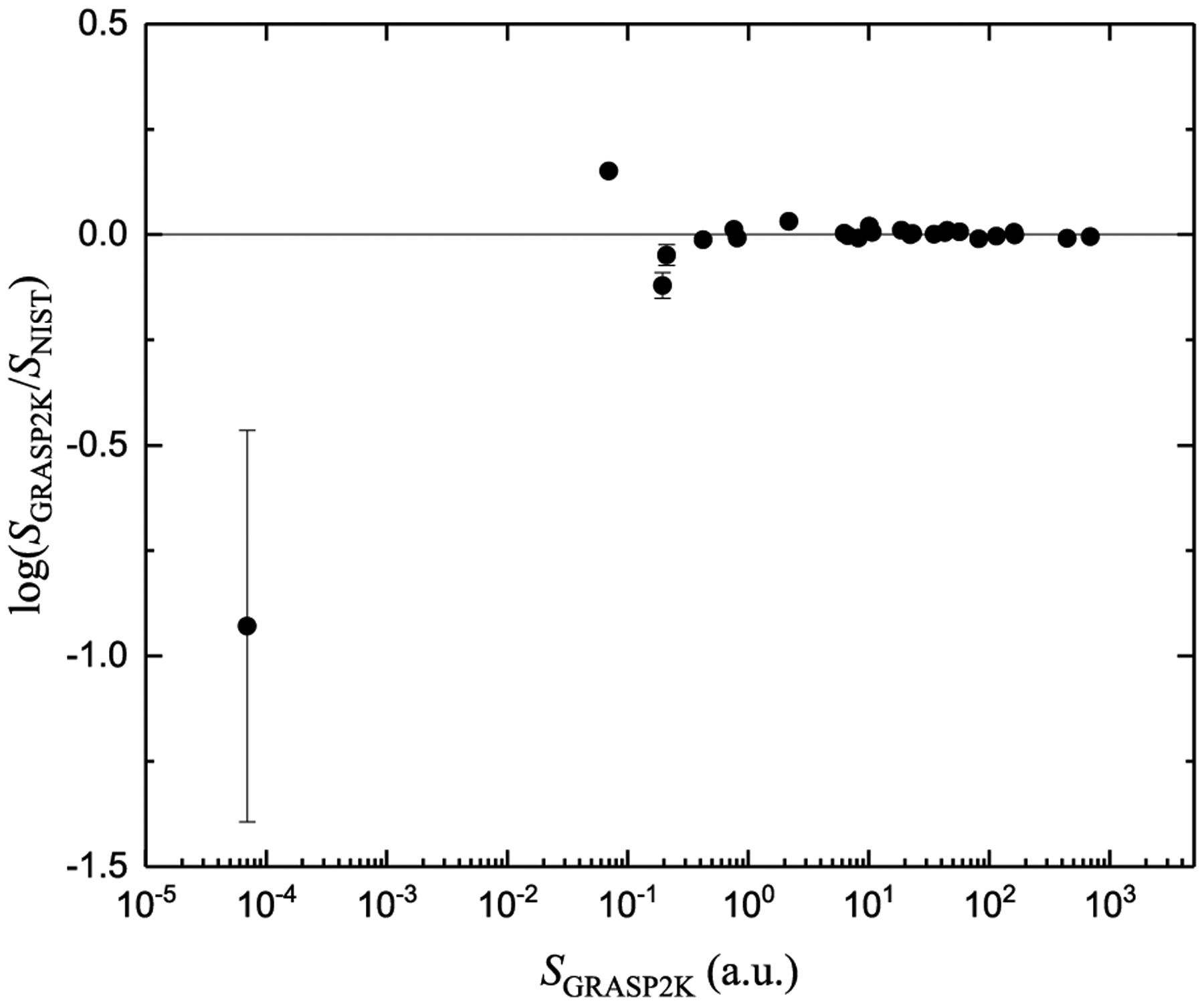
Comparison of the present GRASP2K line strengths with the NIST values as a function of calculated line strengths (in atomic units).
Fig. 2.
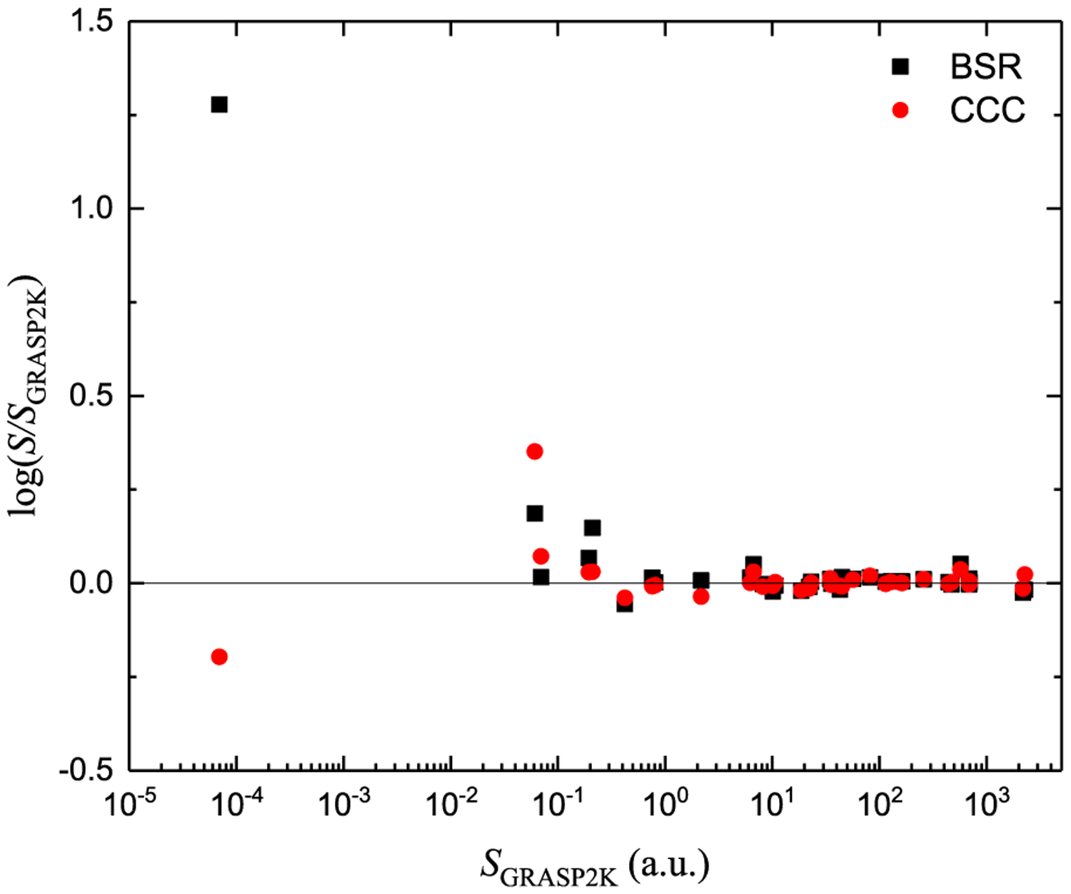
Comparison of the BSR and CCC line strengths with the GRASP2K results as a function of line strengths (in atomic units).
4. Electron-impact excitation cross sections
In the BSR calculations, the threshold energies were changed in the Hamiltonian to match the NIST recommended energies, while in the CCC calculations, the energies from the structure calculations were used. Therefore, it is appropriate to use the electron-impact energy in terms of threshold units (x = E/ΔE), where E is incident electron energy, and ΔE is the threshold energy. The use of the dimensionless, symmetric collision strengths has been preferred over the cross sections σ(E) for fitting through analytic expressions where the former is a slow varying function of incident electron-impact energy as compared to the latter. The electron-impact excitation cross section is related to the collision strength by
| (5) |
where a0 is the Bohr radius, Ry is the Rydberg constant, and gl is the statistical weight of the lower state.
The electron-impact excitations between different atomic states can be classified into three types, viz., dipole-allowed (|ΔL|≤ 1, Δl = ±1, ΔS = 0), dipole-forbidden (ΔL ≠ ±1, ΔS = 0) and spin-forbidden (ΔS ≠ 0) transitions. Here, Δl is the change in the orbital angular momentum of the excited electron. These three types of transitions exhibit different peak magnitudes as well as different energy dependences of the cross section. Therefore, we have employed the following three different analytic functions with six fitting parameters to fit the collision strengths as a function of x:
- Dipole-allowed:
(6) - Dipole-forbidden:
(7) - Spin-forbidden:
(8)
These rather simple analytic formulas preserve the correct threshold and asymptotic behavior of collision strengths and cross sections. Due to the limited number of the fitting parameters, they are well suited for fast calculations of rate coefficients in plasma modeling codes. However, these fits will not be able to accurately represent the resonance structures in the original BSR and CCC data that are typical for close-coupling methods in electron scattering. To this end, the fits thus effectively average the cross sections over the resonance regions. The important question of whether such “resonance-average” fits result in accurate rate coefficients is addressed at the end of this section.
We have checked the data carefully before employing it for fitting, as inconsistent data may give incorrect energy behavior. For most of the transitions CCC and BSR calculations are in good agreement over the entire energy range. However, there are a few exceptions, where the CCC and BSR methods show different high-energy behaviors. The issues regarding the consistency of the data may be due to numerical instabilities or due to insufficient partial waves accounting for the high-energy behavior of cross section curve. The BSR calculation included partial waves with total orbital angular momenta L ≤ 25 explicitly while the higher partial waves were included through a top-up procedure based on geometric extrapolation. The CCC calculations were performed with partial waves up to L = 15 and the contribution of higher partial waves were taken into account through the Born subtraction method [24]. The accuracy of the Born subtraction method was verified by including the contribution for partial waves with L up to 25, and negligible changes were found between the two results [12]. The data for such transitions in the high-energy region are compared with the asymptotic behavior using the van Regemorter formula [25], which employs the use of calculated oscillator strengths. We noticed that the CCC results show the expected high-energy behavior (as given by the van Regemorter formula) while the BSR curve is far away from the van Regemorter curve. Therefore, we have only employed CCC collision strengths at those higher energies for fitting.
Tables 3–5 give the values of fitting coefficients for all possible 171 transitions between all the considered states. The recommended cross sections can be calculated using these fitting coefficients through Eqs. (5)–(8). We have compared the fitted cross sections with the results of the BSR and CCC calculations. As an example, the comparison of the fitted data for the three types of transitions (dipole-allowed, dipole-forbidden, and spin-forbidden) with the BSR and CCC calculations is presented in Figs. 3 and 4, which shows good agreement. For the spin-forbidden transition 43D → 41F, we have used two fit functions of the same form given by Eq. (8) to cover the entire energy range starting from the threshold to reproduce the theoretical data through fitting. For the transition 43F → 41F with a very small threshold energy (ΔE = 2 × 10⁻⁵ eV [15]), the cross sections can be calculated starting from the energy 0.0488 eV using the fitting coefficients given in Table 5. This cross section can be extrapolated linearly for the lower electron energies down to 0 at the threshold energy.
Table 3.
Fitting coefficients in Eq. (6) for electron-impact collision strengths for dipole-allowed transitions. See explanation of Tables.
| i | f | A0 | A1 | A2 | A3 | A4 | A5 |
|---|---|---|---|---|---|---|---|
| 21S | 21P | 1.386[+01] | 3.961[+00] | 6.437[+01] | 5.310[+01] | 4.848[+01] | −6.883[+01] |
| 31P | −9.986[−01] | 4.029[−01] | 2.030[−01] | 4.799[−01] | −1.013[+00] | 4.148[−01] | |
| 41P | −9.990[−01] | 7.001[−02] | 2.649[−03] | 3.992[−01] | −5.288[−01] | 1.516[−01] | |
| 41F | −9.995[−01] | 1.621[−05] | 1.498[−02] | 1.164[−01] | −3.429[−01] | 2.331[−01] | |
| 23P | 33S | −8.669[−01] | 1.545[+01] | −2.277[+01] | 3.767[+01] | −2.411[+01] | 1.646[+01] |
| P3P | 6.003[+00] | 3.697[+01] | 1.074[+02] | 1.107[+02] | 3.442[+02] | −5.622[+02] | |
| 33D | −9.946[−01] | 4.328[+01] | −6.570[+01] | 1.055[+02] | −5.500[+01] | 1.632[+01] | |
| 43S | −9.989[−01] | 1.573[+00] | −1.850[+00] | 1.725[+00] | 1.417[+00] | −7.871[−01] | |
| 43D | −9.998[−01] | 1.227[+01] | −1.572[+01] | 1.800[+01] | 2.641[+00] | −4.550[+00] | |
| 21P | 31S | −9.878[−01] | 2.108[+01] | −2.869[+01] | 4.451[+01] | −1.153[+01] | −1.566[+00] |
| P1D | −9.699[−01] | 1.650[+00] | −2.495[+00] | 2.385[+01] | −4.473[+01] | 2.948[+01] | |
| 31D | −9.969[−01] | 3.940[+01] | −6.680[+01] | 1.091[+02] | −5.280[+01] | 1.173[+01] | |
| 41S | −9.973[−01] | 8.645[−01] | −2.788[−01] | −8.229[−01] | 2.882[+00] | −1.502[+00] | |
| 41D | 7.224[+00] | 5.436[+00] | 2.794[+01] | −9.769[+01] | 1.400[+02] | −3.341[+01] | |
| 33S | 33P | 2.132[+01] | 1.084[+02] | 8.696[+02] | 2.342[−01] | −4.339[+03] | 7.940[+03] |
| 43P | −9.983[−01] | 1.254[+00] | 7.976[+00] | −1.760[+01] | 1.900[+01] | −7.285[+00] | |
| 43F | −7.737[−01] | 4.627[−01] | 5.663[+00] | 5.880[+01] | −1.503[+02] | 9.459[+01] | |
| 31S | 31P | 1.671[+01] | 4.512[+01] | 2.481[+02] | −4.876[+02] | 8.595[+02] | −2.804[+02] |
| 41P | −9.915[−01] | 2.984[−01] | 1.250[+00] | 4.021[−01] | −2.982[+00] | 1.760[+00] | |
| 41F | −2.321[−01] | 4.654[−01] | 1.796[+00] | 4.730[+01] | −1.192[+02] | 7.909[+01] | |
| P1D | 31P | 1.350[+01] | 4.243[+01] | 1.111[+02] | 3.600[+02] | −3.770[+01] | 1.789[+02] |
| 41P | −9.950[−01] | 2.032[+00] | 1.512[+00] | 6.961[−01] | 1.709[+00] | −2.225[+00] | |
| 41F | −9.921[−01] | 4.238[+01] | −6.437[+01] | 7.561[+01] | 2.172[+01] | −3.084[+01] | |
| 33P | 33D | 3.370[+01] | 3.326[+02] | 2.956[+03] | 1.578[+04] | −4.180[+04] | 3.328[+04] |
| 43S | 3.356[+01] | 7.241[+01] | 5.421[+02] | 1.189[+03] | −6.695[+03] | 8.775[+03] | |
| 43D | −9.728[−01] | 7.423[+01] | −1.439[+02] | 3.518[+02] | −3.047[+02] | 1.214[+02] | |
| 31P | 31D | 2.139[+01] | 1.154[+02] | 8.080[+02] | −1.849[+03] | 2.364[+03] | 8.576[+02] |
| 41S | 2.792[+01] | 3.505[+01] | 1.502[+02] | 1.658[+02] | −1.636[+03] | 2.171[+03] | |
| 41D | 1.417[+02] | 1.371[+00] | 1.158[+01] | 1.550[+03] | 5.416[+02] | 3.841[+01] | |
| 33D | 43P | 1.625[+01] | 7.175[+01] | 2.363[+02] | −1.180[+02] | −3.027[+02] | 4.981[+03] |
| 43F | 6.245[+00] | 7.729[+02] | 9.357[+02] | −6.885[+03] | 1.403[+04] | −7.408[+03] | |
| 31D | 41P | 2.815[+01] | 1.083[+02] | 5.615[+02] | 6.960[+02] | −4.811[+03] | 6.075[+03] |
| 41F | 1.199[+01] | 4.366[+02] | 1.262[+03] | −4.915[+03] | 7.056[+03] | −1.939[+03] | |
| 43S | 43P | 2.839[+01] | 6.053[+02] | 2.618[+03] | −8.723[+03] | 7.012[+03] | 2.723[+03] |
| 43F | 1.015[+01] | 5.000[−05] | 9.261[+01] | 7.133[+02] | 1.762[+03] | −2.026[+03] | |
| 41S | 41P | 3.409[+01] | 2.065[+02] | 1.244[+03] | −3.784[+03] | 6.323[+03] | −2.659[+03] |
| 41F | −9.892[−01] | 7.385[−01] | 2.829[+01] | −6.957[+01] | 6.259[+01] | −1.688[+01] | |
| 43P | 43D | 1.987[+01] | 2.194[+03] | 6.663[+03] | −5.109[+04] | 1.125[+05] | −6.643[+04] |
| 41P | 41D | 1.569[+00] | 1.360[+03] | −2.840[+03] | 6.237[+03] | −5.388[+03] | 2.001[+03] |
| 43D | 43F | 1.361[+01] | 2.870[+03] | 7.490[+03] | −4.774[+04] | 9.390[+04] | −5.249[+04] |
| 41F | 41D | 1.468[+01] | 6.166[+02] | 1.580[+03] | −8.392[+03] | 1.330[+04] | −6.235[+03] |
Table 5.
Fitting coefficients in Eq. (8) for electron-impact collision strengths for spin-forbidden transitions. See explanation of Tables.
| i | f | x | A0 | A1 | A2 | A3 | A4 | A5 |
|---|---|---|---|---|---|---|---|---|
| 21S | 23P | 2.856[+00] | −9.978[−01] | 5.059[+01] | −1.806[+02] | 3.484[+02] | −2.173[+02] | |
| 33S | 2.629[+00] | −9.481[−01] | 1.438[−01] | 1.949[+00] | −4.594[+00] | 3.640[+00] | ||
| 33P | 2.995[+00] | −9.980[−01] | 1.025[+00] | −1.952[+00] | 2.419[+00] | −9.788[−01] | ||
| P3P | 4.202[+00] | 1.482[−01] | 7.135[+00] | −2.893[+01] | 4.082[+01] | −1.903[+01] | ||
| 33D | 3.567[+00] | −9.996[−01] | 3.095[+00] | −8.889[+00] | 1.082[+01] | −4.866[+00] | ||
| 43S | 2.689[+00] | −9.990[−01] | 3.071[−02] | 3.812[−01] | −6.797[−01] | 4.252[−01] | ||
| 43P | 2.999[+00] | −9.907[−01] | 2.700[−01] | −2.808[−01] | 4.660[−02] | 1.610[−01] | ||
| 43D | 3.575[+00] | −9.968[−01] | 1.272[+00] | −3.795[+00] | 4.801[+00] | −2.203[+00] | ||
| 43F | 4.101[+00] | −8.509[−01] | 2.246[−01] | −5.927[−01] | 7.270[−01] | −2.994[−01] | ||
| 23P | 21P | 3.119[+00] | −9.973[−01] | 1.017[+02] | −3.188[+02] | 4.651[+02] | −2.456[+02] | |
| 31S | 3.160[+00] | −9.985[−01] | 4.443[+00] | −1.452[+01] | 3.121[+01] | −2.043[+01] | ||
| P1D | 2.996[+00] | −9.678[−01] | 4.523[+01] | −5.377[+01] | 1.719[+01] | 8.571[+00] | ||
| 31P | 2.941[+00] | −9.849[−01] | 4.280[+00] | 1.452[−02] | −1.105[+01] | 9.475[+00] | ||
| 31D | 2.918[+00] | −9.984[−01] | 4.727[+00] | 7.432[+00] | −2.908[+01] | 1.883[+01] | ||
| 41S | 3.150[+00] | −9.988[−01] | 7.565[−01] | −1.242[+00] | 2.093[+00] | −1.107[+00] | ||
| 41P | 2.941[+00] | −9.995[−01] | 1.301[+00] | −5.773[−01] | −1.496[+00] | 1.278[+00] | ||
| 41F | 3.906[+00] | −9.990[−01] | 9.421[−01] | −2.102[+00] | 2.184[+00] | −4.216[−01] | ||
| 41D | 3.028[+00] | −9.526[−01] | 1.799[+00] | −1.538[+00] | 1.669[−01] | 1.147[−01] | ||
| 21P | 33S | 3.334[+00] | −9.743[−01] | 7.645[+01] | −2.894[+02] | 4.318[+02] | −2.160[+02] | |
| 33P | 2.886[+00] | −9.973[−01] | 2.186[+01] | −6.638[+01] | 1.053[+02] | −5.333[+01] | ||
| P3P | 2.830[+00] | 1.073[−01] | 5.257[+01] | −2.343[+02] | 4.141[+02] | −2.325[+02] | ||
| 33D | 3.275[+00] | 6.203[+01] | 4.320[+01] | −1.429[+02] | 1.577[+02] | 6.231[+02] | ||
| 43S | 3.589[+00] | −9.985[−01] | 8.329[+00] | −2.420[+01] | 2.994[+01] | −1.265[+01] | ||
| 43P | 3.040[+00] | −9.593[−01] | 4.670[+00] | −1.445[+01] | 2.511[+01] | −1.294[+01] | ||
| 43D | 3.259[+00] | −9.989[−01] | 9.553[+00] | −3.435[+01] | 5.456[+01] | −2.896[+01] | ||
| 43F | 3.909[+00] | −9.989[−01] | 9.312[+00] | −2.712[+01] | 3.543[+01] | −1.751[+01] | ||
| 33S | 31S | 2.041[+00] | 2.275[+04] | 1.457[−01] | 1.923[+03] | 1.890[+05] | −1.637[+05] | |
| P1D | 3.572[+00] | 3.448[+05] | 1.090[+03] | −1.198[+02] | −5.617[+04] | 1.165[+07] | ||
| P3P | 3.406[+00] | 1.638[+06] | 6.045[+03] | 8.814[+05] | −1.789[+06] | 9.020[+05] | ||
| 13P | 2.989[+00] | −9.652[−01] | 3.220[+01] | −7.496[+01] | 6.360[+01] | −2.016[+01] | ||
| 31D | 3.612[+00] | −9.996[−01] | 4.486[+01] | −1.410[+02] | 1.776[+02] | −7.969[+01] | ||
| 41S | 3.090[+00] | 8.875[+02] | 6.582[−02] | 1.554[+02] | −1.473[+03] | 4.062[+03] | ||
| 41P | 2.908[+00] | −9.959[−01] | 3.342[+00] | −1.125[+01] | 2.334[+01] | −1.510[+01] | ||
| 41F | 4.366[+00] | 1.245[+03] | 1.266[+02] | −5.512[+02] | 1.397[+02] | 5.031[+03] | ||
| 41D | 3.655[+00] | −1.720[−01] | 1.275[+01] | −5.315[+01] | 8.375[+01] | −4.047[+01] | ||
| 31S | 33P | 3.056[+00] | 2.098[+05] | 8.972[+01] | −1.073[+04] | 1.234[+06] | 2.536[+06] | |
| P3P | 3.243[+00] | 3.732[+00] | 4.450[+00] | −1.243[+01] | 1.143[+01] | −3.445[+00] | ||
| 33D | 3.381[+00] | −9.980[−01] | 1.065[+02] | −3.992[+02] | 5.655[+02] | −2.710[+02] | ||
| 43S | 2.664[+00] | 4.351[+02] | 6.520[−01] | 7.206[+01] | −6.602[+02] | 2.151[+03] | ||
| 43P | 2.633[+00] | −9.135[−01] | 1.506[−01] | 1.161[+01] | −2.624[+01] | 1.746[+01] | ||
| 43D | 3.702[+00] | −9.981[−01] | 2.321[+01] | −9.807[+01] | 1.482[+02] | −7.245[+01] | ||
| 43F | 4.501[+00] | 7.456[+03] | 4.130[+02] | −2.673[+03] | 4.520[+03] | 3.149[+04] | ||
| P1D | 33P | 3.654[+00] | 6.986[+05] | 5.105[+04] | −2.732[+06] | 5.632[+07] | −4.000[+07] | |
| P3P | 2.657[+00] | 1.374[+03] | 3.359[+02] | 6.902[+03] | −1.557[+04] | 8.368[+03] | ||
| 33D | 1.987[+00] | 2.143[+03] | 2.328[−02] | 8.603[+02] | 2.846[+04] | 5.556[+04] | ||
| 43S | 3.690[+00] | 2.197[+05] | 1.709[+02] | 5.629[+02] | −3.399[+04] | 1.570[+06] | ||
| 43P | 3.624[+00] | 1.259[+02] | 1.214[+02] | −6.372[+02] | 5.295[+02] | 2.353[+03] | ||
| 43D | 2.412[+00] | 3.308[+02] | 7.993[−02] | 2.232[+02] | −1.360[+03] | 5.540[+03] | ||
| 43F | 3.673[+00] | 5.652[+02] | 6.629[+01] | 4.527[+02] | −2.850[+03] | 7.639[+03] | ||
| 33P | 31P | 1.896[+00] | 6.593[+04] | 1.834[−01] | 5.579[+03] | 3.862[+06] | −3.361[+06] | |
| 31D | 4.213[+00] | 6.494[+05] | 1.745[+04] | −4.046[+05] | 6.950[+06] | 3.039[+07] | ||
| 41S | 3.361[+00] | −9.897[−01] | 3.549[+01] | −6.970[+01] | 5.258[+01] | −1.507[+01] | ||
| 41P | 2.956[+00] | 4.616[+03] | 1.206[+00] | 1.525[+03] | −1.449[+04] | 1.082[+05] | ||
| 41F | 3.653[+00] | −9.997[−01] | 2.114[+02] | −7.124[+02] | 9.215[+02] | −4.183[+02] | ||
| 41D | 3.265[+00] | 4.028[+03] | 7.893[−01] | 8.965[+02] | −4.724[+03] | 5.184[+04] | ||
| P3P | 31P | 2.751[+00] | 7.514[+05] | 2.069[+03] | 2.907[+05] | 4.203[+05] | −5.193[+05] | |
| 31D | 2.000[+00] | 5.796[+02] | 6.509[−02] | 6.866[+02] | −2.211[+03] | 3.385[+03] | ||
| 41S | 4.292[+00] | 1.259[+08] | 3.377[+03] | −2.786[+05] | 1.182[+07] | 3.752[+07] | ||
| 41P | 4.202[+00] | 8.271[+07] | 1.537[+04] | −1.664[+06] | 7.300[+07] | −1.190[+07] | ||
| 41F | 3.491[+00] | 1.396[+02] | 1.210[+00] | 4.542[+01] | −2.164[+02] | 3.218[+02] | ||
| 41D | 2.949[+00] | 1.454[+03] | 4.604[+01] | −1.317[+02] | 1.162[+03] | 5.870[+01] | ||
| 43P | 1.809[+00] | 2.091[+03] | 4.404[+00] | 5.088[+02] | −1.486[+03] | 2.267[+03] | ||
| 43F | 1.615[+00] | 1.048[+01] | 3.412[−01] | 1.651[+00] | −5.607[+00] | 6.319[+00] | ||
| 33D | 2.242[+00] | 6.567[+04] | 1.412[+03] | 5.692[+03] | 1.309[+04] | −9.420[+03] | ||
| 43S | 3.418[+00] | 8.732[+07] | 3.825[+03] | 4.488[+06] | −4.552[+06] | 7.948[+06] | ||
| 43D | 1.992[+00] | 7.380[+03] | 6.403[+00] | 3.835[+03] | −1.211[+04] | 1.350[+04] | ||
| 31P | 33D | 4.403[+00] | 7.249[+09] | 8.723[+06] | −3.001[+09] | 3.788[+11] | −2.977[+11] | |
| 43S | 3.220[+00] | 1.966[+01] | 6.345[+01] | −2.947[+02] | 3.807[+02] | 1.802[+02] | ||
| 43P | 2.777[+00] | 1.909[+03] | 8.732[+00] | 1.163[+03] | −1.105[+04] | 6.365[+04] | ||
| 43D | 4.248[+00] | 4.670[+04] | 2.336[+03] | −1.472[+04] | −3.552[+04] | 1.146[+06] | ||
| 43F | 3.944[+00] | 4.069[+05] | 2.086[+03] | −9.609[+04] | 2.073[+06] | 5.517[+06] | ||
| 33D | 31D | 3.022[+00] | 5.302[+05] | 8.982[+03] | −5.747[+05] | 3.894[+07] | −1.479[+07] | |
| 41S | 3.100[+00] | 1.722[+05] | 7.570[−01] | 1.288[+04] | 1.779[+05] | 2.487[+06] | ||
| 41P | 4.762[+00] | 1.163[+08] | 3.792[+05] | −3.230[+07] | 9.048[+08] | 1.875[+09] | ||
| 41F | 3.886[+00] | 2.420[+05] | 3.649[+03] | −5.495[+04] | 3.193[+06] | 9.448[+06] | ||
| 41D | 3.336[+00] | 5.780[+04] | 4.359[+02] | −1.217[+03] | 2.048[+05] | 1.487[+06] | ||
| 31D | 43S | 1–95 | 2.727[+00] | 1.860[+04] | 7.113[+03] | −2.701[+04] | 1.013[+05] | 1.843[+04] |
| 95–∞ | 1.377[+00] | 1.503[+04] | 3.110[−04] | −5.359[+01] | 3.699[+06] | −7.794[+06] | ||
| 43P | 4.167[+00] | 1.002[+06] | 8.084[+04] | −2.436[+06] | 3.495[+07] | 1.882[+07] | ||
| 43D | 3.084[+00] | 1.291[+06] | 2.266[+03] | −1.372[+05] | 1.830[+07] | 1.139[+08] | ||
| 43F | 4.213[+00] | 7.707[+05] | 1.053[+05] | −3.450[+06] | 5.552[+07] | −2.031[+07] | ||
| 43S | 41S | 2.878[+00] | 1.643[+07] | 8.801[+03] | 5.281[+05] | 1.635[+08] | −2.682[+07] | |
| 41P | 3.056[+00] | 1.433[+06] | 6.182[+01] | −2.400[+04] | 6.902[+06] | 3.233[+06] | ||
| 41F | 2.588[+00] | 4.986[+04] | 6.328[−03] | −2.060[+01] | 4.353[+04] | 2.221[+06] | ||
| 41D | 3.644[+00] | 5.212[+01] | 2.562[+02] | −1.356[+03] | 2.756[+03] | −1.304[+03] | ||
| 41S | 43P | 2.989[+00] | 5.510[+06] | 5.638[+01] | −4.683[+04] | 3.630[+07] | 6.235[+07] | |
| 43D | 3.337[+00] | 8.377[+01] | 3.481[+02] | −1.812[+03] | 3.388[+03] | 1.076[+03] | ||
| 43F | 4.894[+00] | 2.901[+07] | 6.128[+05] | −2.970[+07] | 4.826[+08] | −2.217[+08] | ||
| 43P | 41P | 1.543[+00] | 1.492[+02] | 5.362[+00] | 1.530[+03] | −5.060[+02] | 3.457[+03] | |
| 41F | 3.905[+00] | 3.916[+06] | 1.819[+05] | −1.065[+07] | 2.527[+08] | 2.952[+08] | ||
| 41D | 4.509[+00] | 3.300[+07] | 1.286[+06] | −7.591[+07] | 1.501[+09] | −1.159[+09] | ||
| 41P | 43D | 4.319[+00] | 1.989[+09] | 1.017[+07] | −1.544[+09] | 1.126[+11] | −4.471[+10] | |
| 43F | 3.973[+00] | 5.479[+07] | 4.888[+05] | −5.579[+07] | 3.424[+09] | −3.428[+09] | ||
| 43D | 41F | 1–544 | 2.383[+00] | 7.107[+02] | 1.451[+03] | 7.512[+03] | 2.240[+04] | −2.020[+04] |
| 544–∞ | 3.248[+00] | 1.445[+09] | 7.174[+01] | 8.384[+07] | 2.188[+11] | 1.467[+13] | ||
| 41D | 2.350[+00] | 6.561[+01] | 3.400[+02] | −1.442[+03] | 4.921[+03] | −3.379[+03] | ||
| 43F | 41F | 2440–∞ | 2.416[+00] | 6.407[+10] | 1.459[+08] | 6.306[+07] | −1.709[+08] | 1.170[+08] |
| 41D | 1–107 | 1.503[+00] | 6.436[+01] | −7.748[−01] | 1.271[+03] | −1.888[+03] | 8.904[+02] | |
| 107–∞ | 4.667[+00] | 4.496[+10] | 3.105[+08] | −7.666[+10] | 1.008[+13] | −3.979[+13] |
Fig. 3.
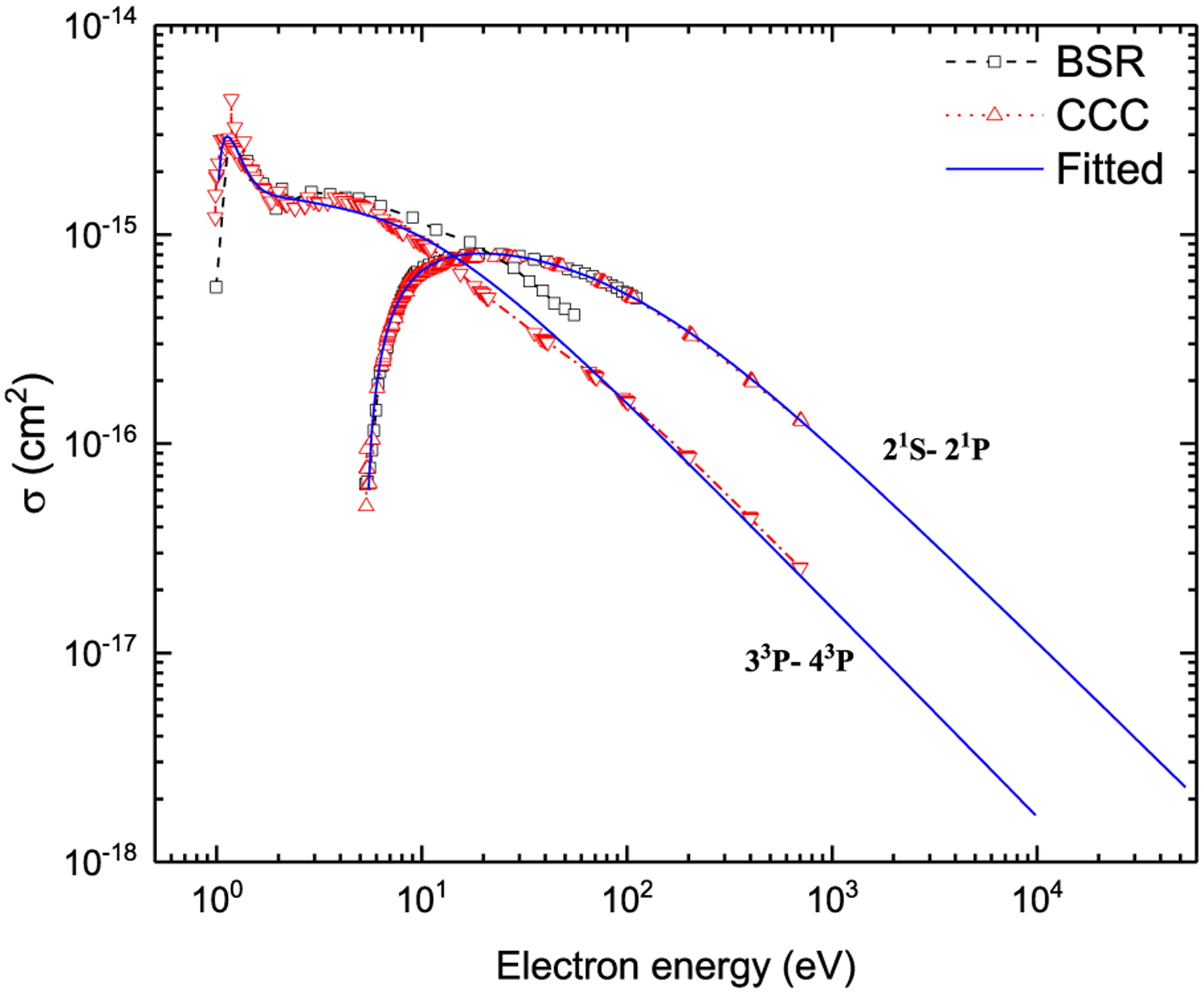
Electron-impact excitation cross sections for the dipole-allowed (21S → 21P) and dipole-forbidden (33P → 43P) transitions. Dashed lines with squares, dotted lines with triangles and solid lines represent BSR, CCC and fitted results respectively.
Fig. 4.
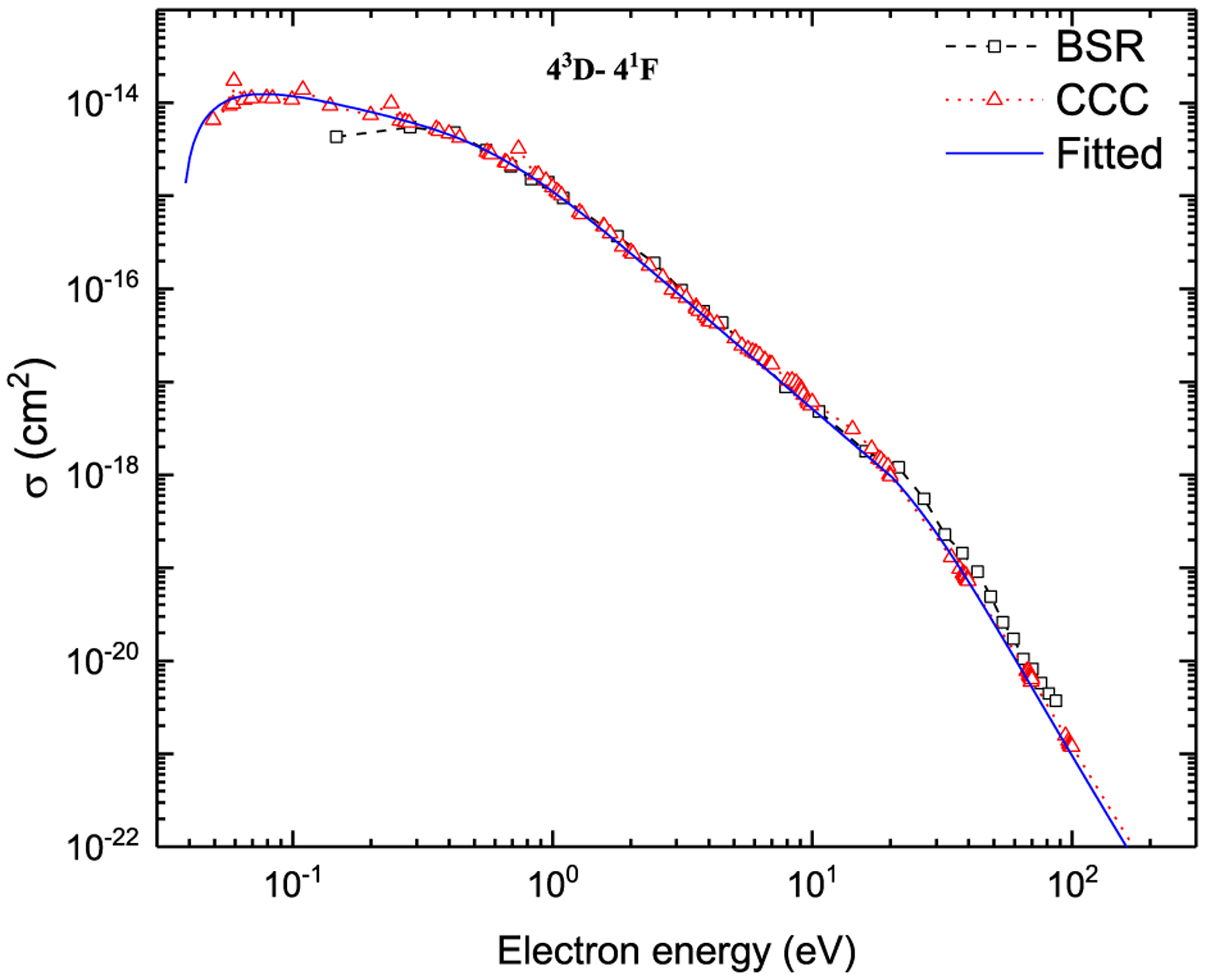
Electron-impact excitation cross sections for the spin-forbidden (43D → 41F) transition.
The standard way to determine the accuracy of the fitted cross sections is through their root mean square (rms) value. However, this method is somewhat misleading in our case due to the presence of resonances in the cross sections. We found that the fitted cross sections are accurate within a few percent except for the values in the resonance region where the deviation is slightly greater. Another way to check the accuracy of the fits is to compare the rate coefficients obtained from the fitted cross sections and the original data. The rate coefficients are calculated using the following equation:
| (9) |
where me is the electron mass and fM(E) is the Maxwellian electron energy distribution function (EEDF). The use of a Maxwellian EEDF is a valid assumption for fusion plasmas and is generally employed to provide the recommended rate coefficients (see, e.g., [26]). In Fig. 5, several rate coefficients calculated with the fit cross sections are compared with those calculated with the original CCC data. It was found as expected that the difference is largest for low temperatures Te ≲ ΔE. Overall, the accuracy of the rate coefficients for most of the transitions is estimated to be within 10%. For very few spin-forbidden transitions with small cross sections, it is higher only at the electron temperatures close to the threshold energy. Those few transitions have ΔE close to 1 eV to 2 eV except for the 23S → 43F transition with ΔE = 8.461 eV.
Fig. 5.
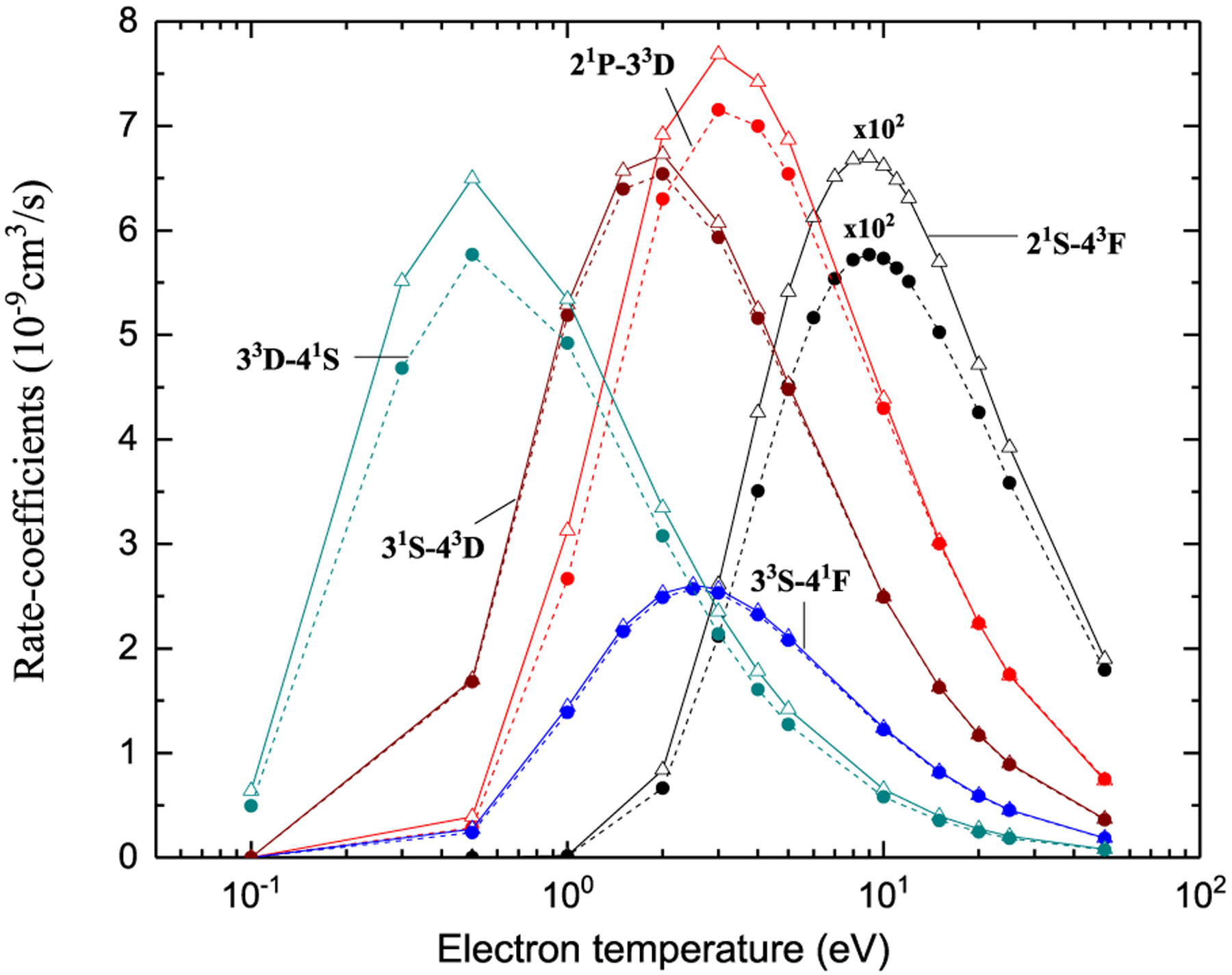
Rate coefficients for electron-impact excitation in Be. Solid lines with triangles represent CCC results while the dashed lines with filled circles are fitted results.
The graphs of all recommended cross sections obtained using the fitting coefficients given in Tables 3–5 through Eqs. (5)–(8) are displayed in Figs. 7–42 as a function of incident electron energy.
5. Electron-impact ionization cross sections
We have used the available BSR and CCC data to provide the recommended fitted ionization cross sections using the following equation [27],
| (10) |
where E (in eV) is the incident electron energy, I (in eV) is the ionization potential and Ai are the fitting coefficients.
Electron-impact ionization cross sections from the ground state (21S) and the two lowest excited terms (21P and 23P) are available from both the BSR and CCC calculations. However, only CCC data are available from the higher excited terms. The ionization cross sections from BSR and CCC calculations were compared with the previous available RMPS [8] and TDCC [9] cross sections for 21S and 23P terms, and good agreement was observed among all the theoretical results [12]. The comparison of fitted electron-impact ionization cross sections from the 21S state with the BSR and CCC results is presented in Fig. 6, which shows an excellent agreement. The fitting coefficients for electron-impact ionization from all considered 19 terms are given in Table 6. The fitted cross sections are also presented in Figs. 43–48.
Fig. 6.
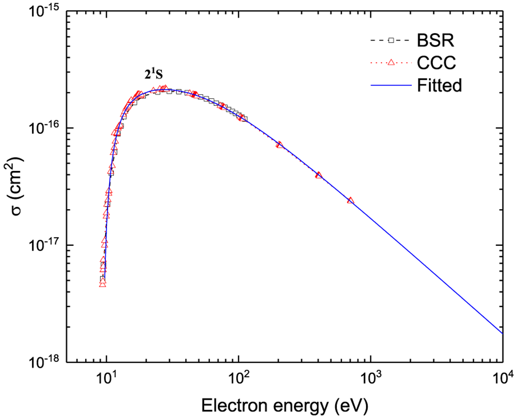
Electron-impact ionization cross sections from the 21S state.
Table 6.
Fitting coefficients in Eq. (10) for electron-impact ionization. See explanation of Tables.
| Term | A0 | A1 | A2 | A3 | A4 | A5 |
|---|---|---|---|---|---|---|
| 21S | 5.288[−03] | 1.149[−02] | 2.761[+00] | −4.591[+00] | 3.418[+00] | 0.000[+00] |
| 23P | 1.676[−01] | 9.504[−02] | −2.394[+00] | 1.535[+01] | −2.669[+01] | 1.564[+01] |
| 21P | 5.747[−01] | 8.530[−02] | −5.691[+00] | 2.510[+01] | −3.900[+01] | 2.052[+01] |
| 33S | 2.250[−01] | 4.443[−01] | −5.374[+00] | 2.284[+01] | −3.227[+01] | 1.526[+01] |
| 31S | 3.733[−01] | 2.210[−01] | −4.860[+00] | 2.017[+01] | −2.991[+01] | 1.506[+01] |
| P1D | 5.073[−01] | −8.928[−02] | −3.578[+00] | 1.297[+01] | −1.930[+01] | 9.997[+00] |
| 33P | 3.526[−01] | 3.689[−01] | −4.943[+00] | 1.762[+01] | −2.413[+01] | 1.145[+01] |
| P3P | 9.580[−01] | −9.561[−01] | −3.567[−01] | −1.342[+00] | 2.713[+00] | −2.276[+00] |
| 31P | 3.430[−01] | 3.599[−01] | −4.788[+00] | 1.624[+01] | −2.163[+01] | 9.966[+00] |
| 33D | 3.016[−01] | 3.370[−01] | −4.087[+00] | 1.376[+01] | −1.723[+01] | 7.485[+00] |
| 31D | 2.554[−01] | 4.559[−01] | −4.850[+00] | 1.623[+01] | −2.015[+01] | 8.200[+00] |
| 43S | 1.375[−01] | 7.384[−01] | −6.113[+00] | 1.903[+01] | −2.127[+01] | 7.946[+00] |
| 41S | 1.934[−01] | 7.466[−01] | −7.095[+00] | 2.311[+01] | −2.797[+01] | 1.139[+01] |
| 43P | 2.036[−01] | 8.182[−01] | −6.858[+00] | 2.026[+01] | −2.399[+01] | 1.012[+01] |
| 41P | 1.700[−01] | 8.204[−01] | −6.687[+00] | 1.967[+01] | −2.243[+01] | 8.878[+00] |
| 43D | 2.293[−01] | 4.998[−01] | −4.512[+00] | 1.329[+01] | −1.730[+01] | 8.572[+00] |
| 43F | 9.155[−02] | 4.100[−01] | −1.862[+00] | 3.209[+00] | −3.579[−01] | −1.391[+00] |
| 41F | 9.035[−02] | 5.111[−01] | −2.680[+00] | 5.902[+00] | −3.768[+00] | 4.129[−02] |
| 41D | 1.288[−01] | 5.585[−01] | −3.784[+00] | 1.017[+01] | −1.108[+01] | 4.598[+00] |
6. Conclusions
The electron-impact excitation and ionization cross sections obtained from a critical assessment of the recent theoretical data [12] calculated using the BSR and CCC methods have been fitted through the analytic expressions for the lowest 19 terms of configurations 2snl (n ≤ 4) and 2p2 of Be I. The analytic fits for the electron-impact excitation as well as ionization follow the correct asymptotic behavior. The recommended as well as the CCC electron-impact excitation cross sections were integrated over the Maxwellian electron energy distribution to obtain the rate coefficients and good agreement was observed. The recommended rate coefficients should be accurate within 10% with respect to the BSR and CCC data for use in plasma modeling applications. We have also reported the oscillator strengths for the dipole-allowed transitions between the 19 terms of configurations 2snl (n ≤ 4) and 2p2 using MCDHF method and found very good agreement with the BSR and CCC calculations.
Explanation of Tables
Table 1.
Energies of atomic terms 2snl (n ≤ 4) and 2p2 below first ionization potential (in eV)
Table 2.
Oscillator strengths for the dipole-allowed transitions between 2snl (n ≤ 4) and 2p2 terms.
For the oscillator strengths: aE±b means a × 10b and the number in parentheses is df in Eq. (4). Unc. in parentheses refers to the uncertainties in the NIST line strengths. The code letters imply the following uncertainties: A ≤ 3%, B ≤ 10%, C ≤ 25%, and D ≤ 50%.
Table 3.
Fitting coefficients for electron-impact collision strengths for dipole-allowed transitions.
| i | initial term |
| f | final term |
| A0, …A5 | Fitting coefficients in Eq. (6) |
Table 4.
Fitting coefficients for electron-impact collision strengths for dipole-forbidden transitions.
| i | initial term |
| f | final term |
| A0 , … A5 | Fitting coefficients in Eq. (7) |
Table 5.
Fitting coefficients for electron-impact collision strengths for spin-forbidden transitions.
| i | initial term |
| f | final term |
| x | Electron-impact energy in the energy threshold units |
| A0 , … A5 | Fitting coefficients in Eq. (8) |
Table 6.
Fitting coefficients for electron-impact ionization cross sections
| i | initial term |
| A0 , … A5 | Fitting coefficients in Eq. (10) |
In Tables 3–6, the numbers in square brackets refer to powers of 10: a[b] implies a × 10b.
Explanation of Graphs
Figures 7–42. Recommended electron-impact excitation cross sections for transitions between 2snl (n ≤ 4) and 2p2 terms.
Figure 7:
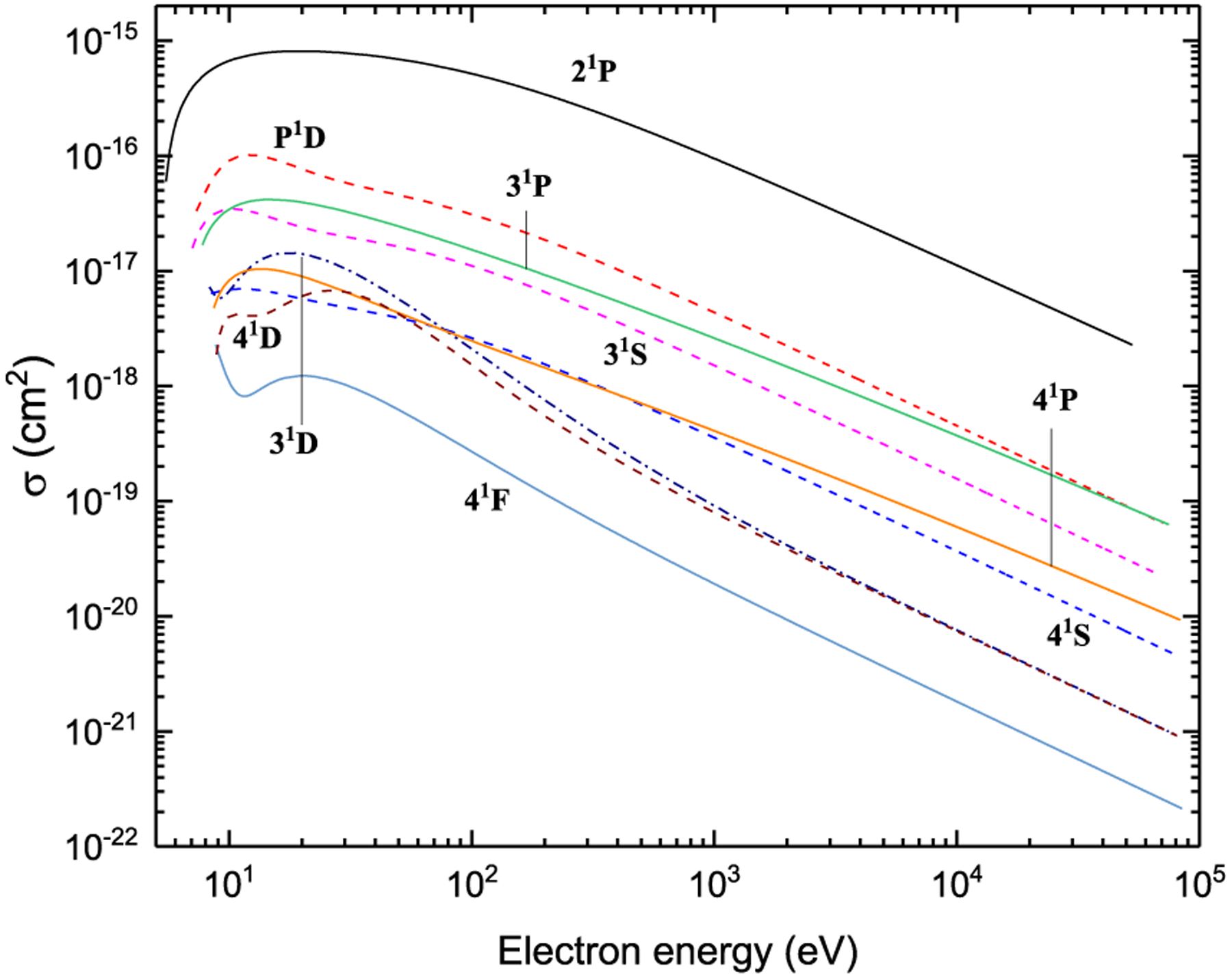
Excitation from 21S
Figure 8:
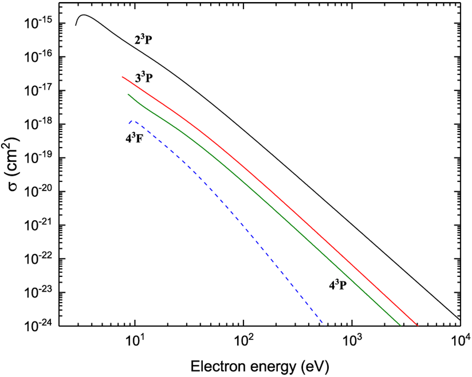
Excitation from 21S
Figure 9:
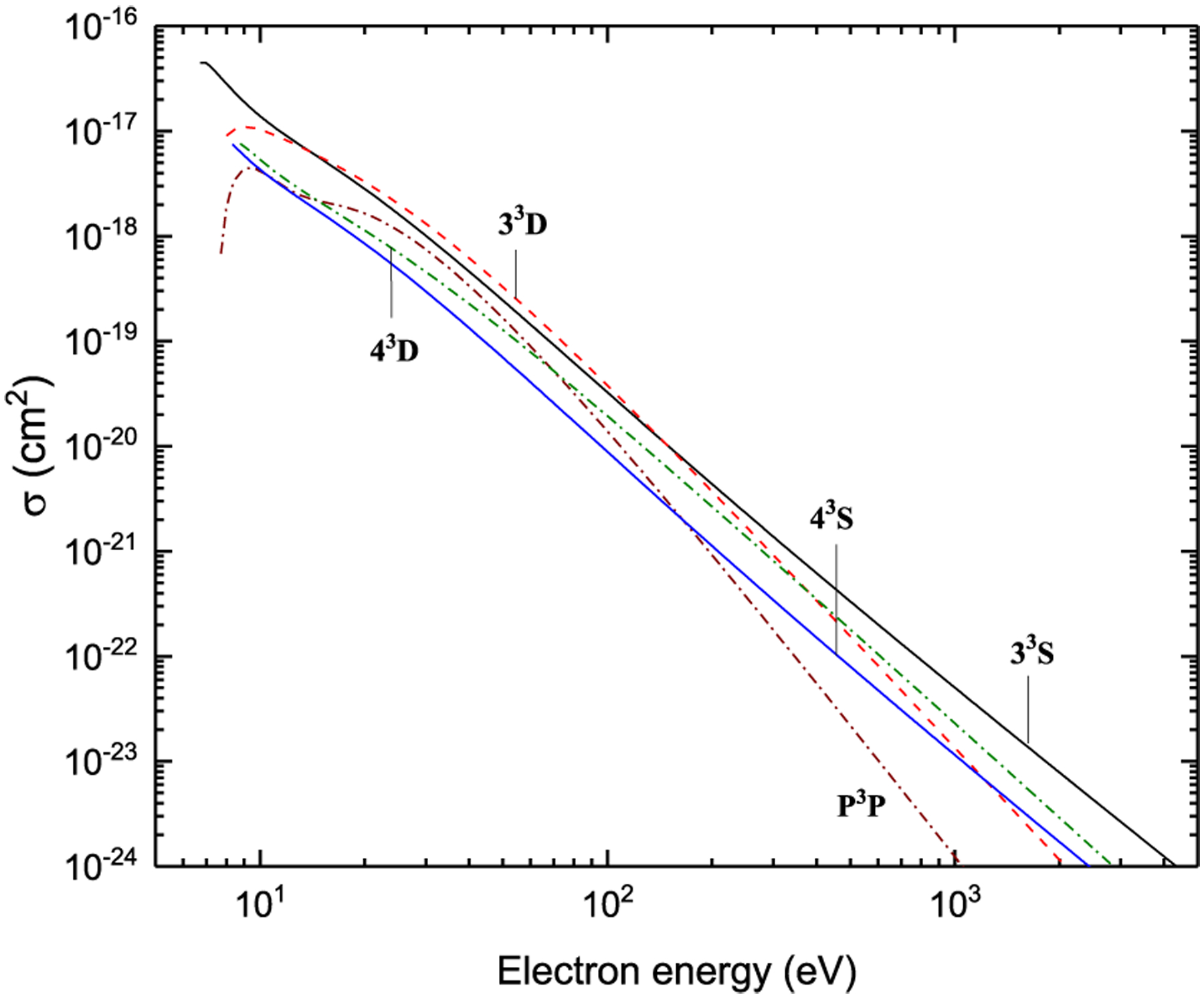
Excitation from 21S
Figure 10:
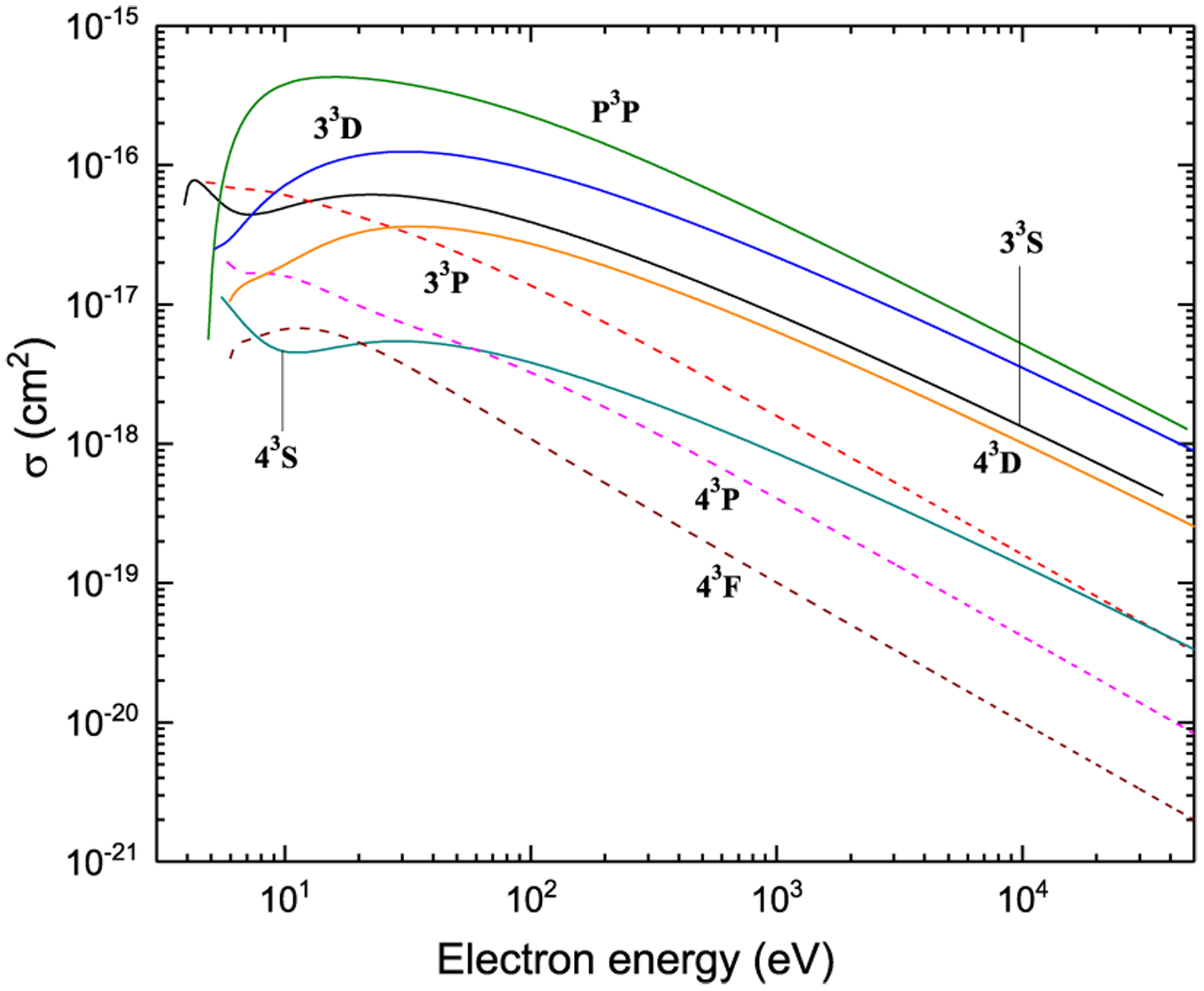
Excitation from 23P
Figure 11:
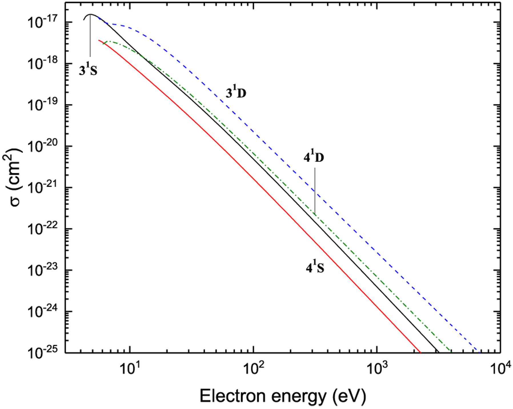
Excitation from 23P
Figure 12:
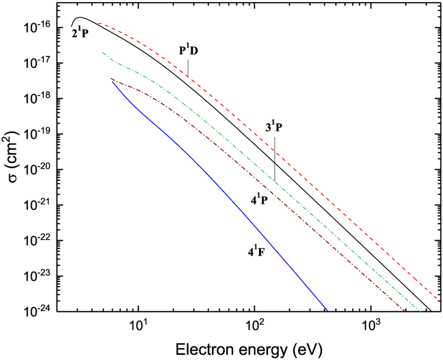
Excitation from 23P
Figure 13:
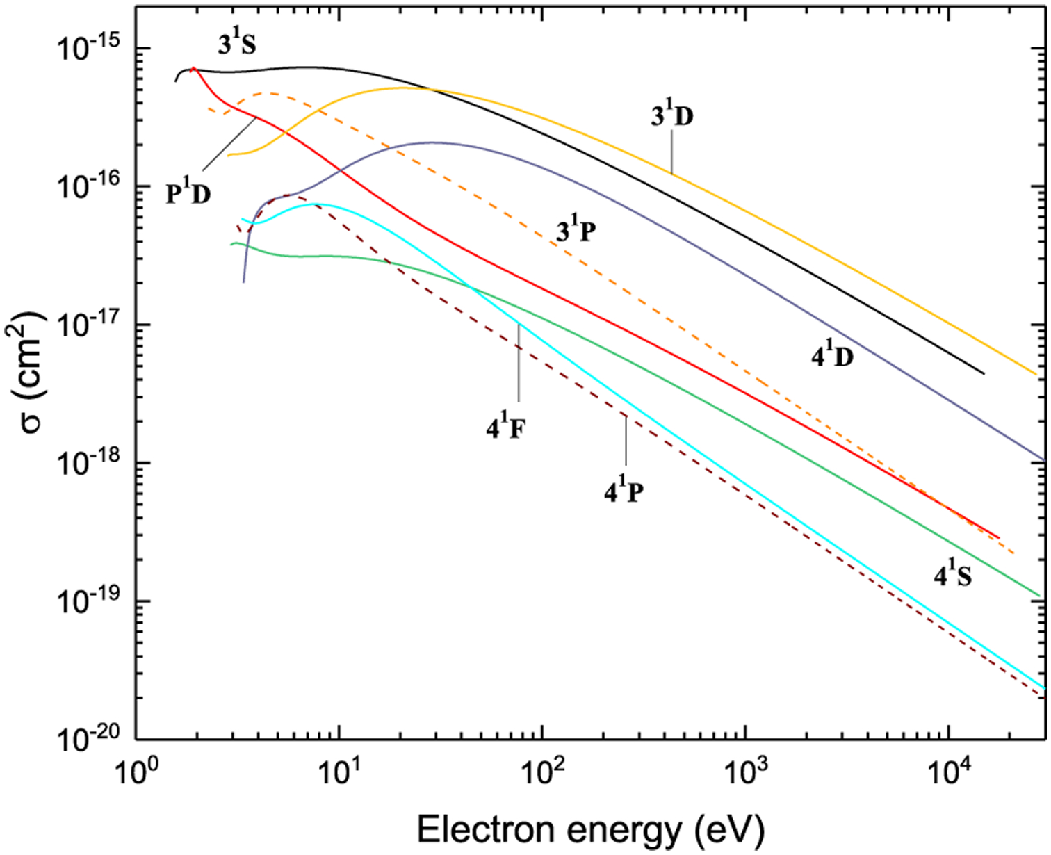
Excitation from 21P
Figure 14:
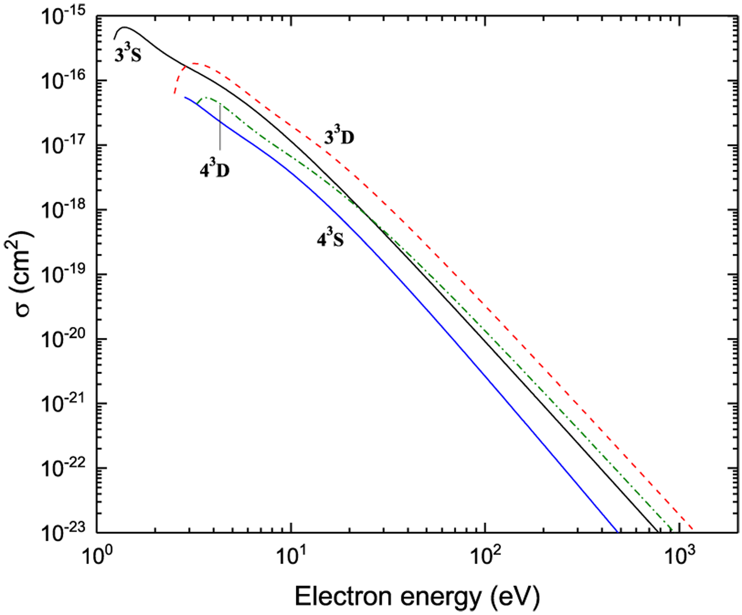
Excitation from 21P
Figure 15:
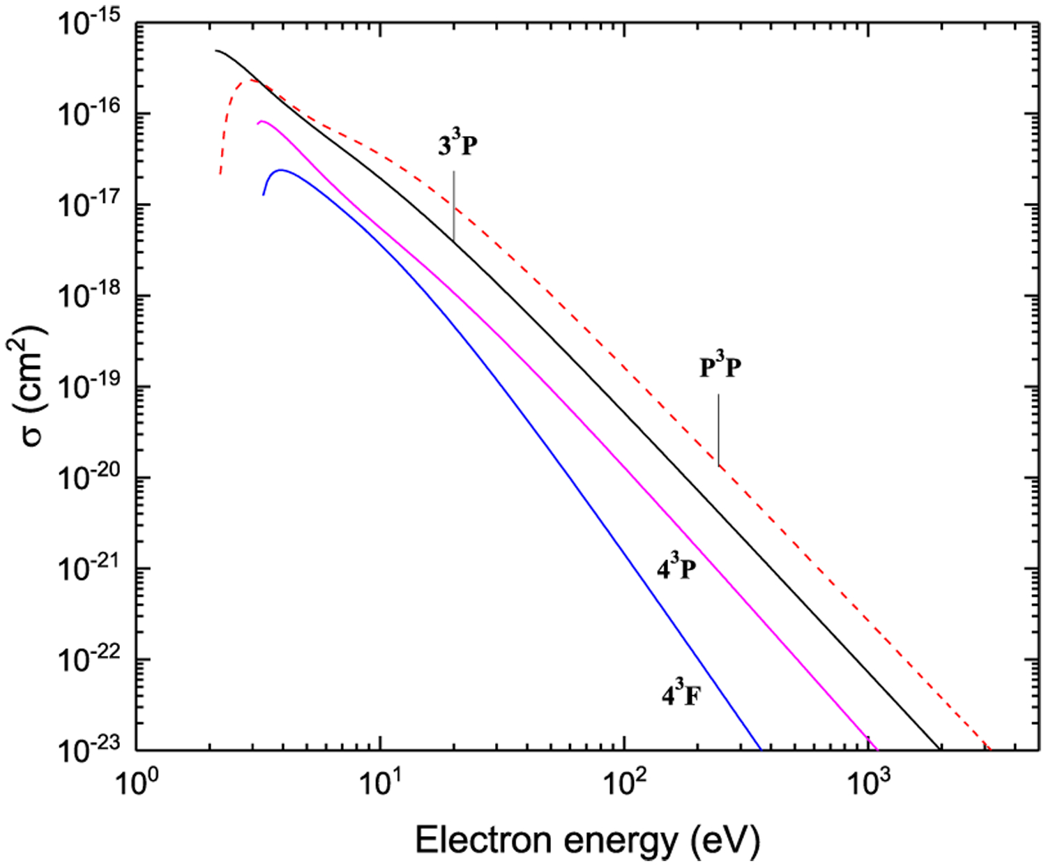
Excitation from 21P
Figure 16:
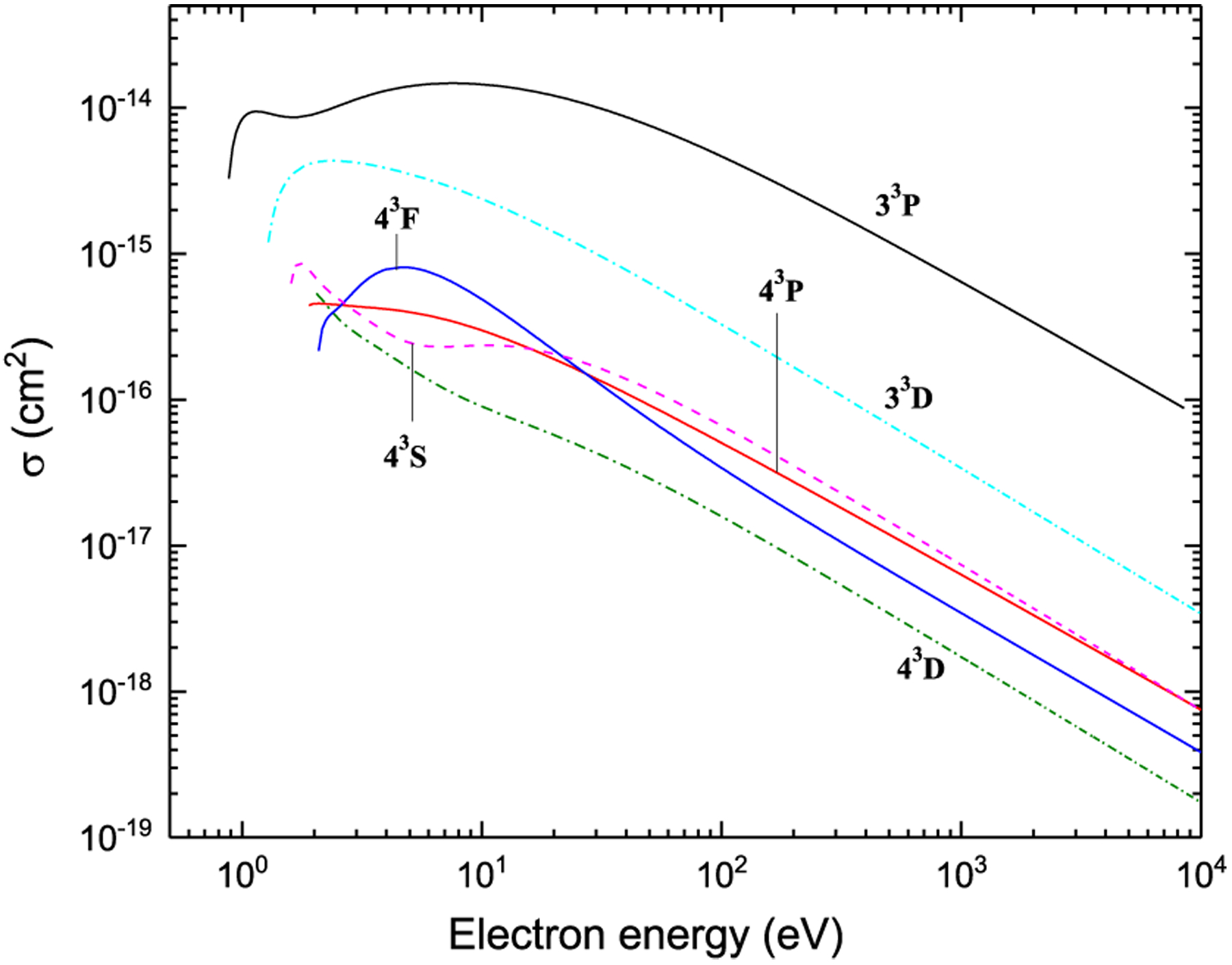
Excitation from 33S
Figure 17:
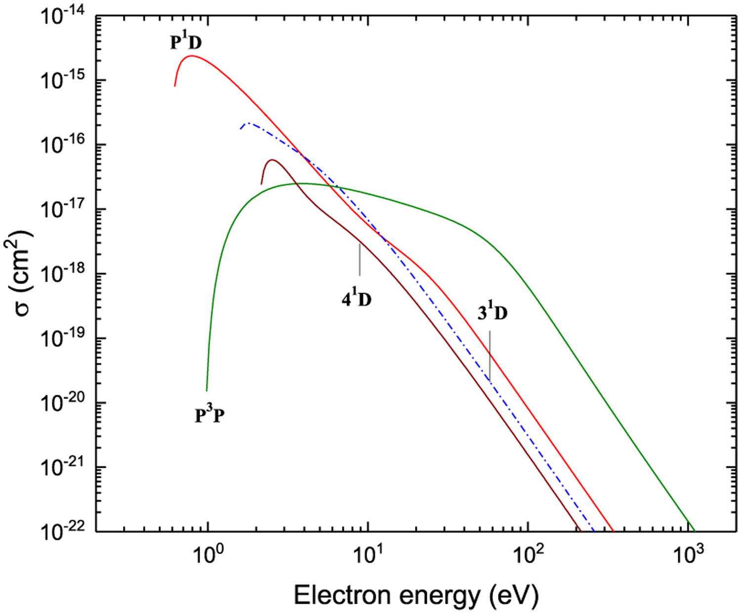
Excitation from 33S
Figure 18:
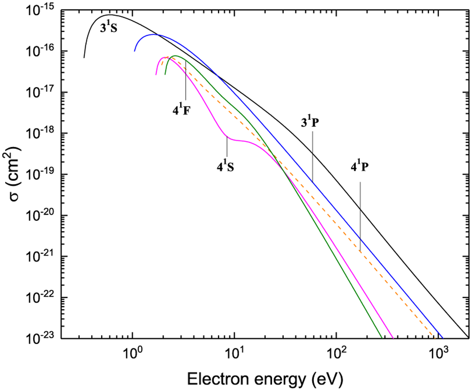
Excitation from 33S
Figure 19:
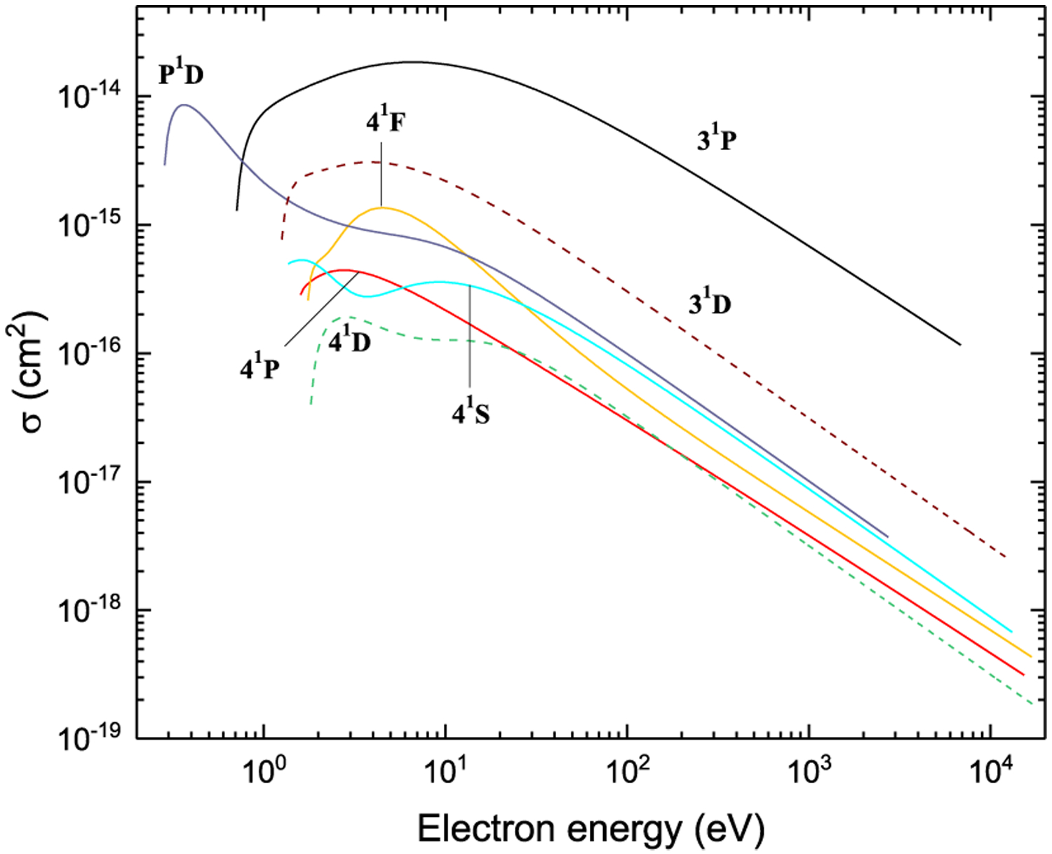
Excitation from 31S
Figure 20:
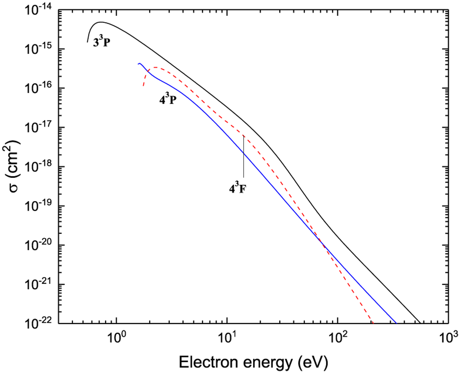
Excitation from 31S
Figure 21:
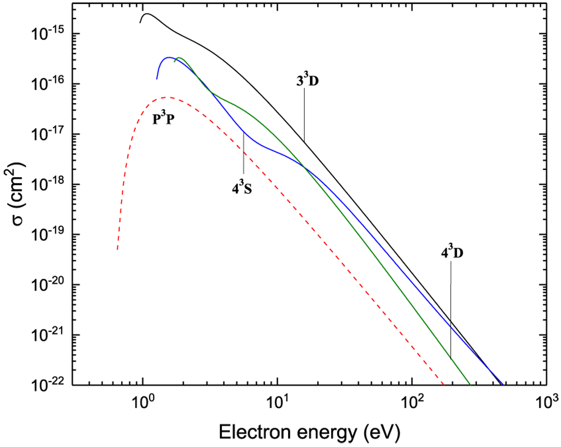
Excitation from 31S
Figure 22:
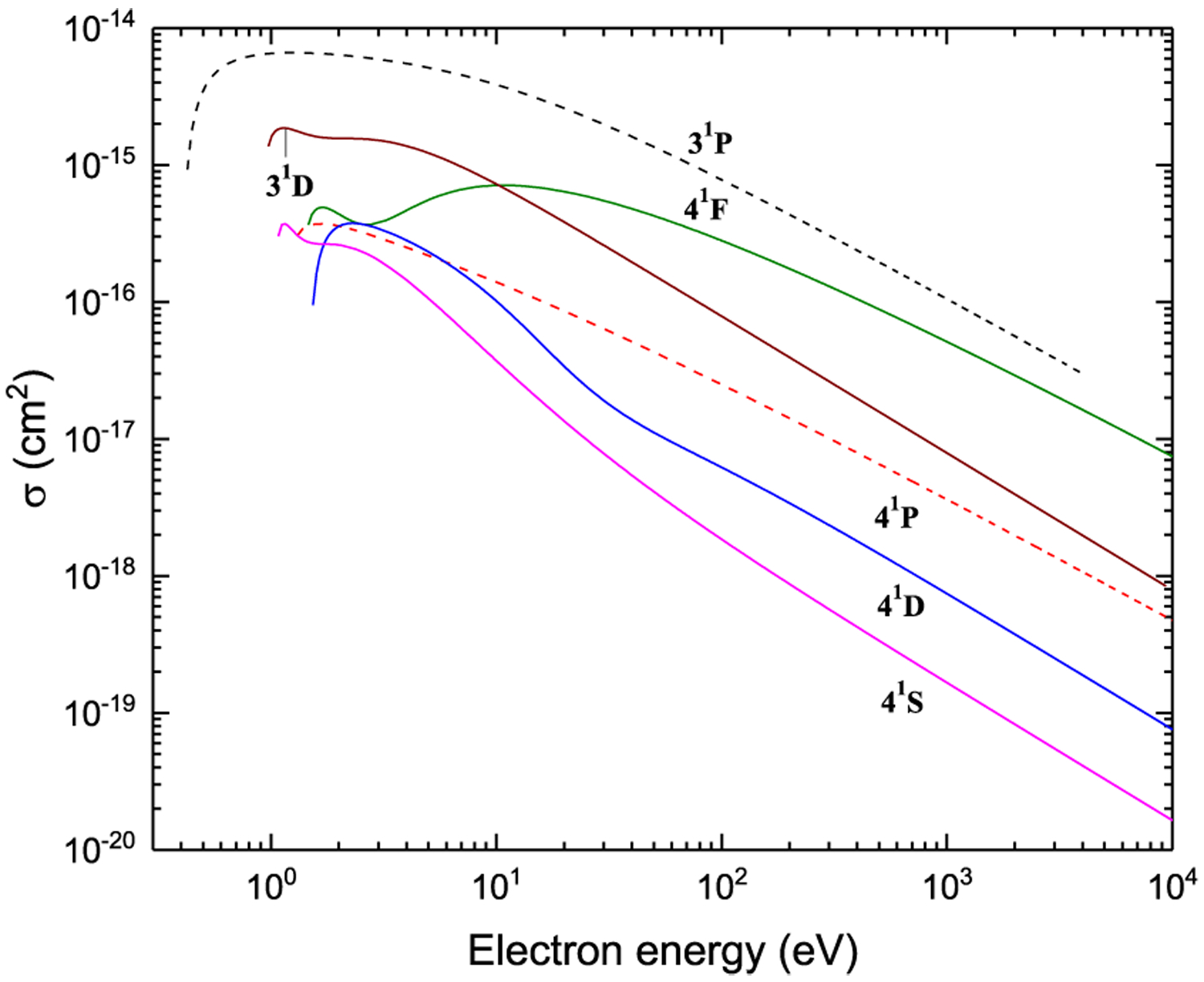
Excitation from P1D
Figure 23:
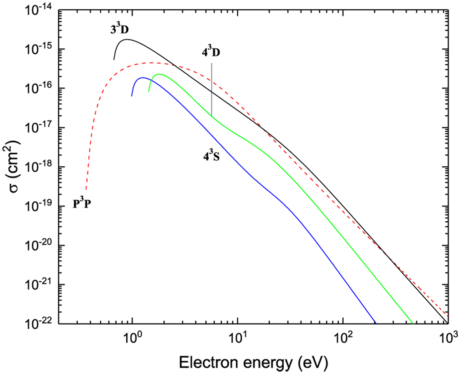
Excitation from P1D
Figure 24:
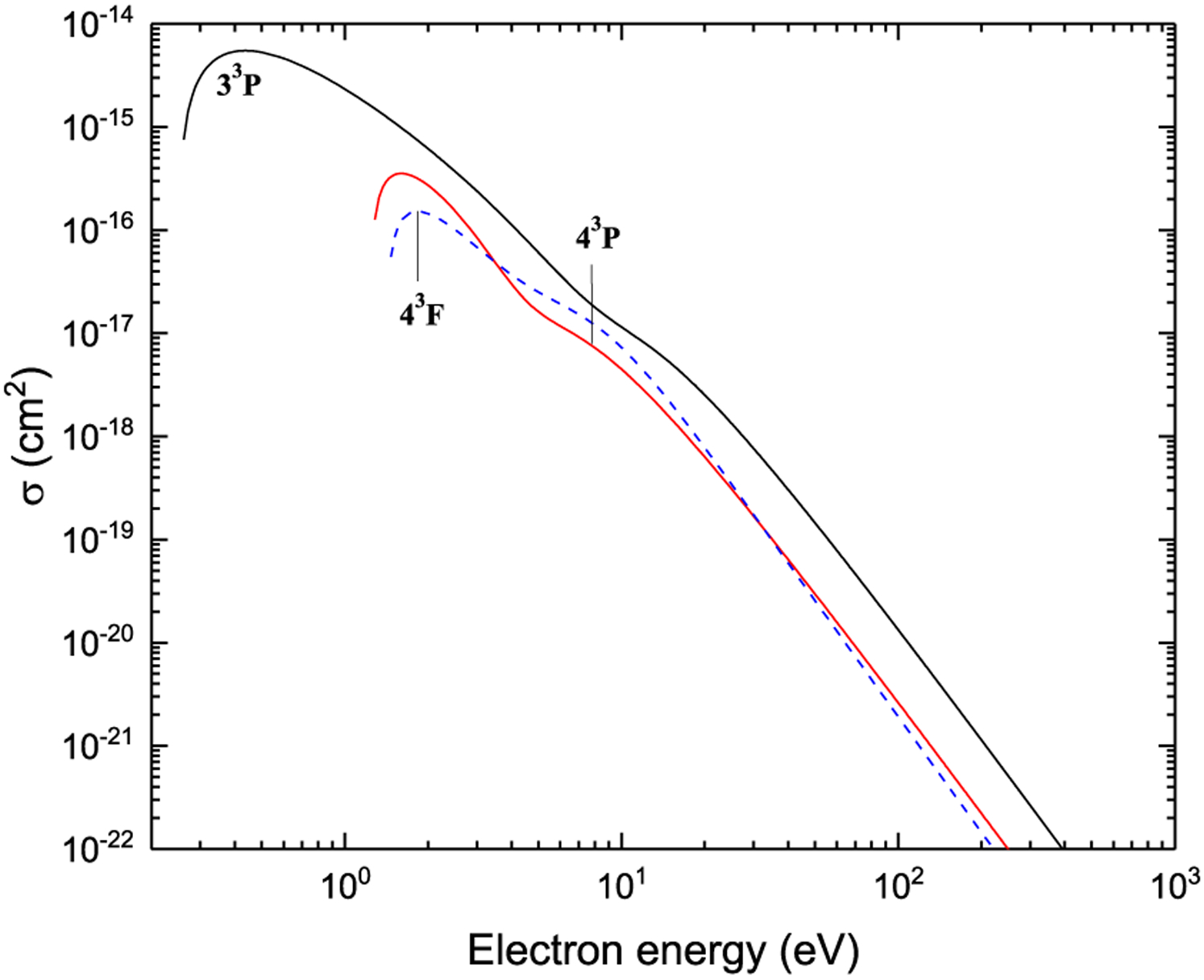
Excitation from P1D
Figure 25:
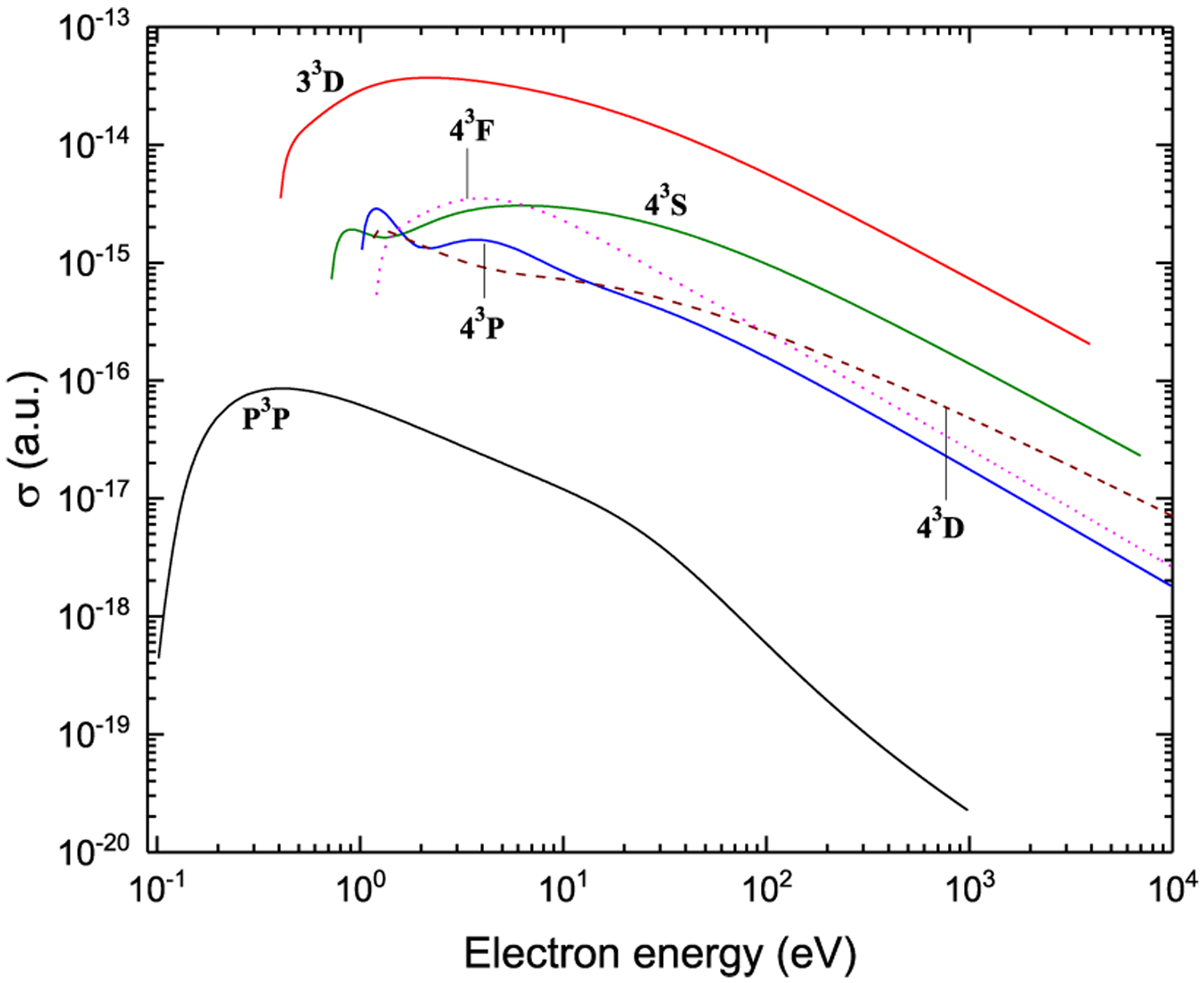
Excitation from 33P
Figure 26:
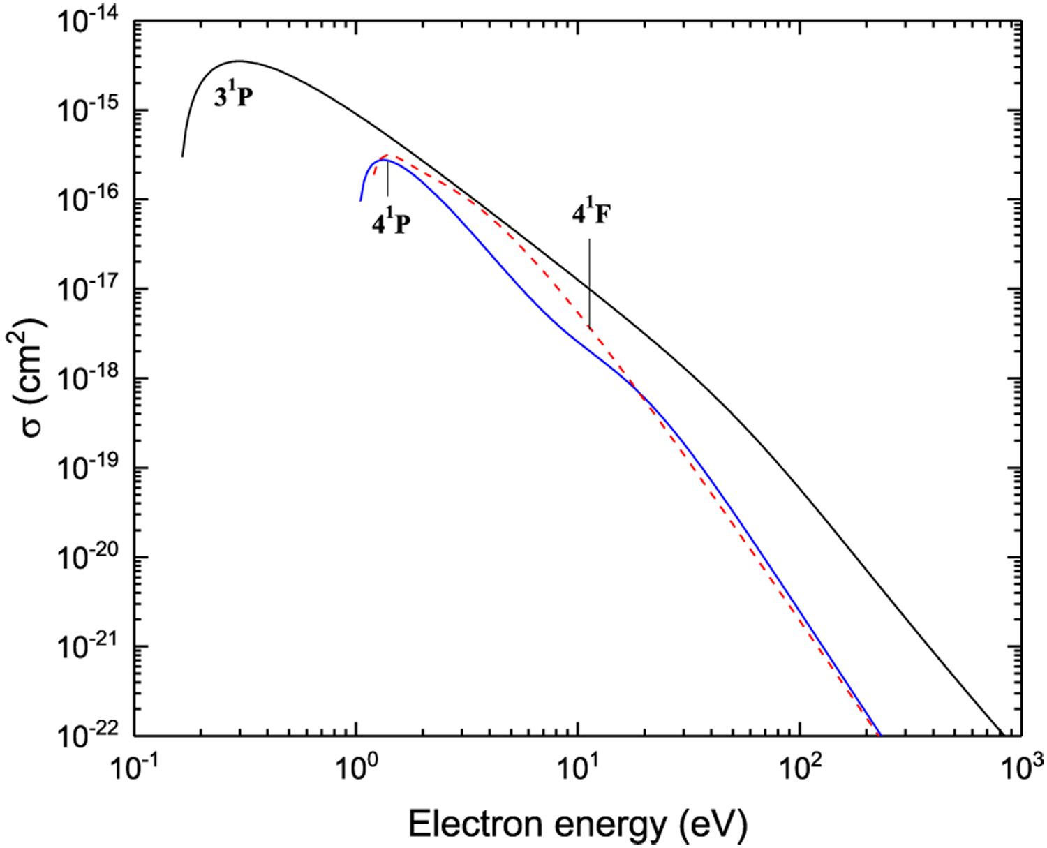
Excitation from 33P
Figure 27:
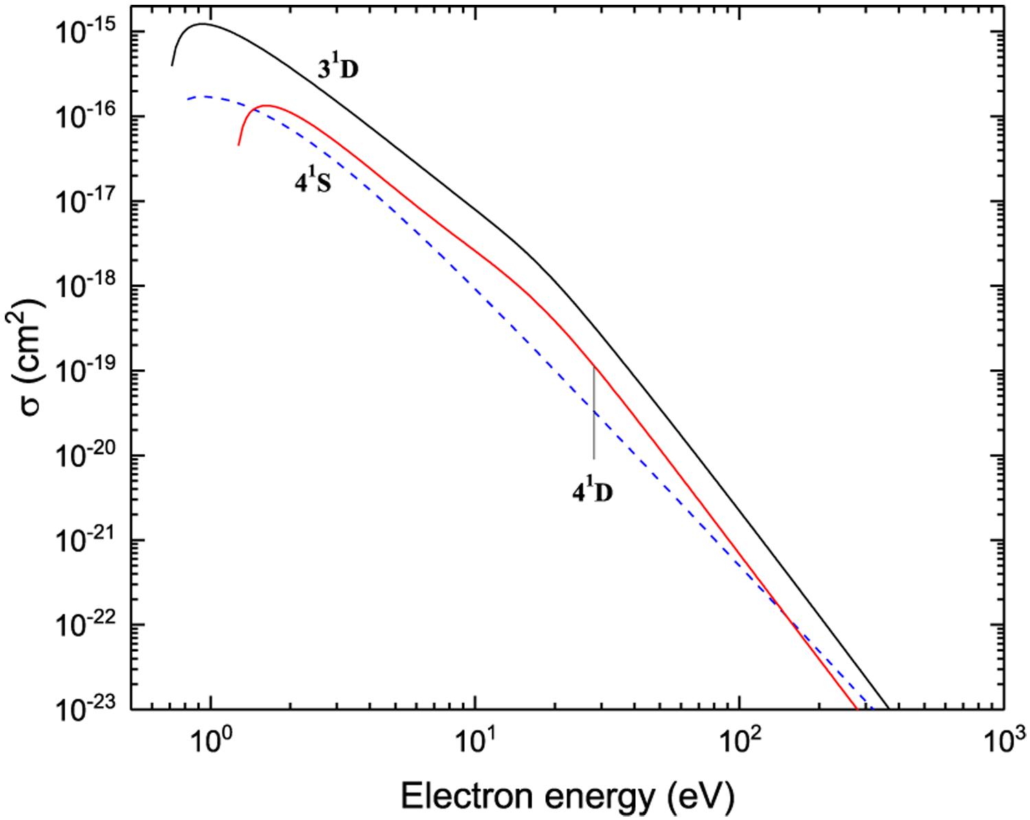
Excitation from 33P
Figure 28:
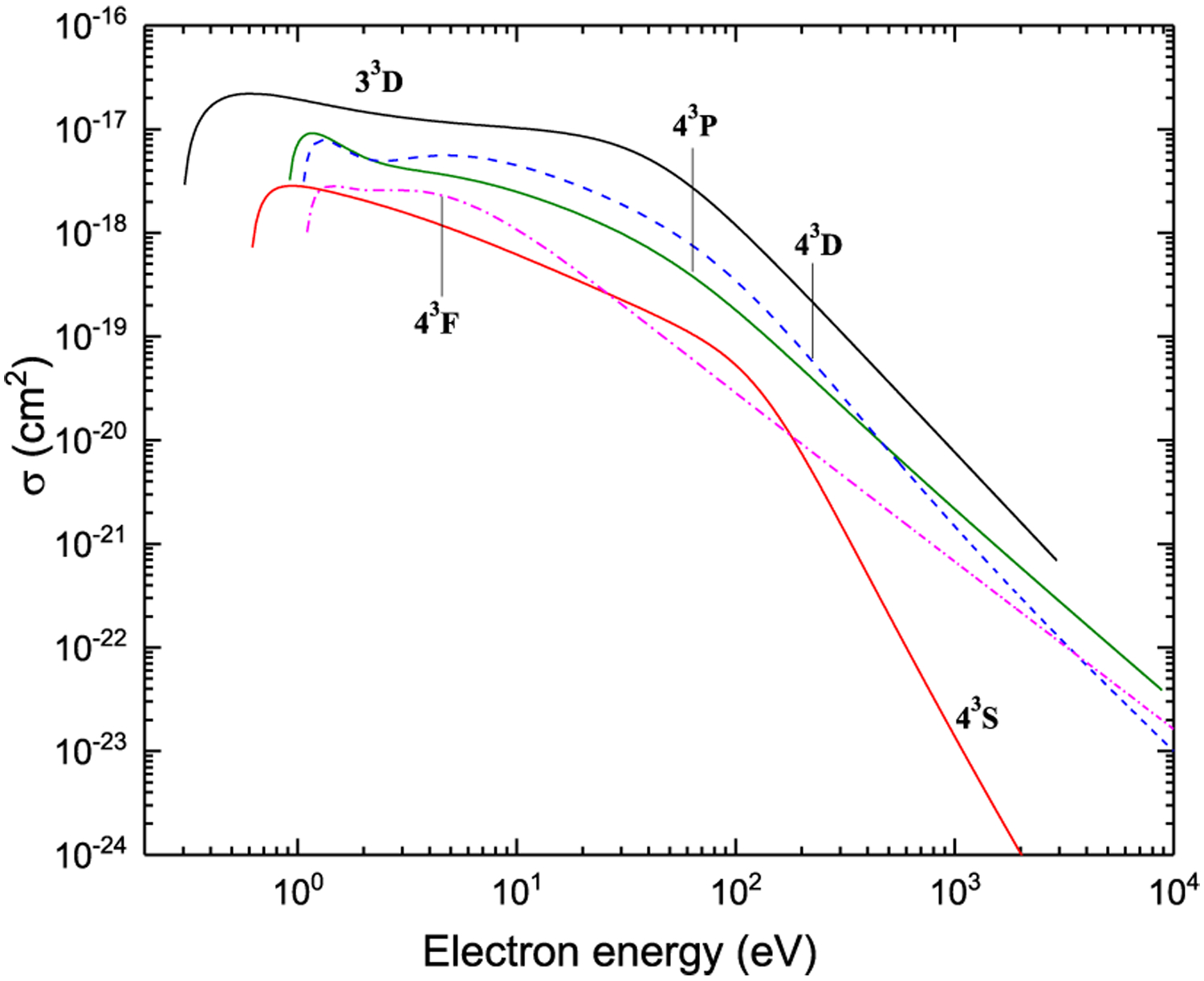
Excitation from P3P
Figure 29:
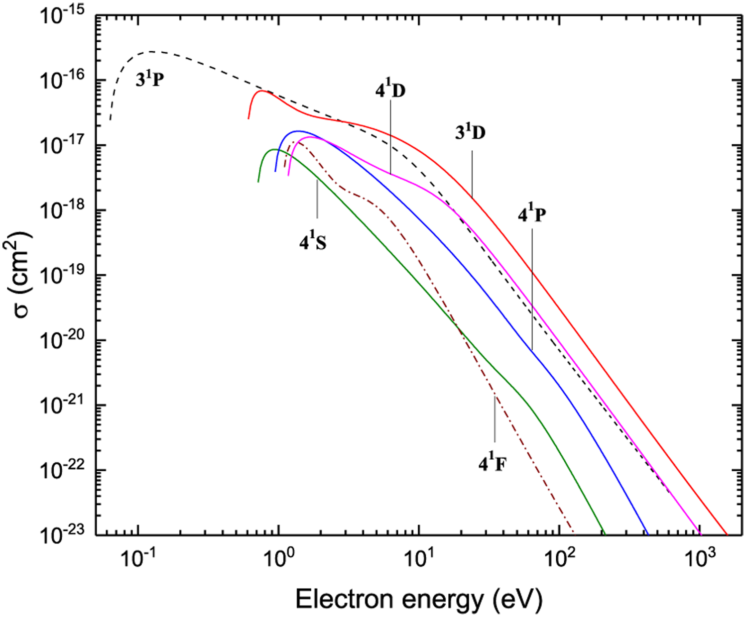
Excitation from P3P
Figure 30:
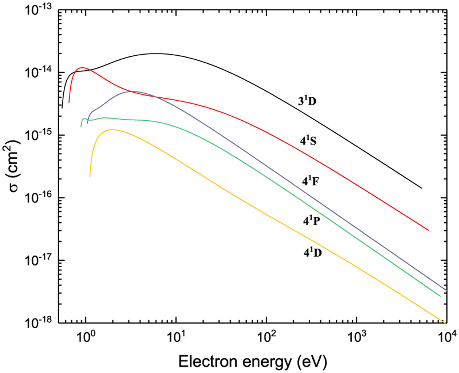
Excitation from 31P
Figure 31:
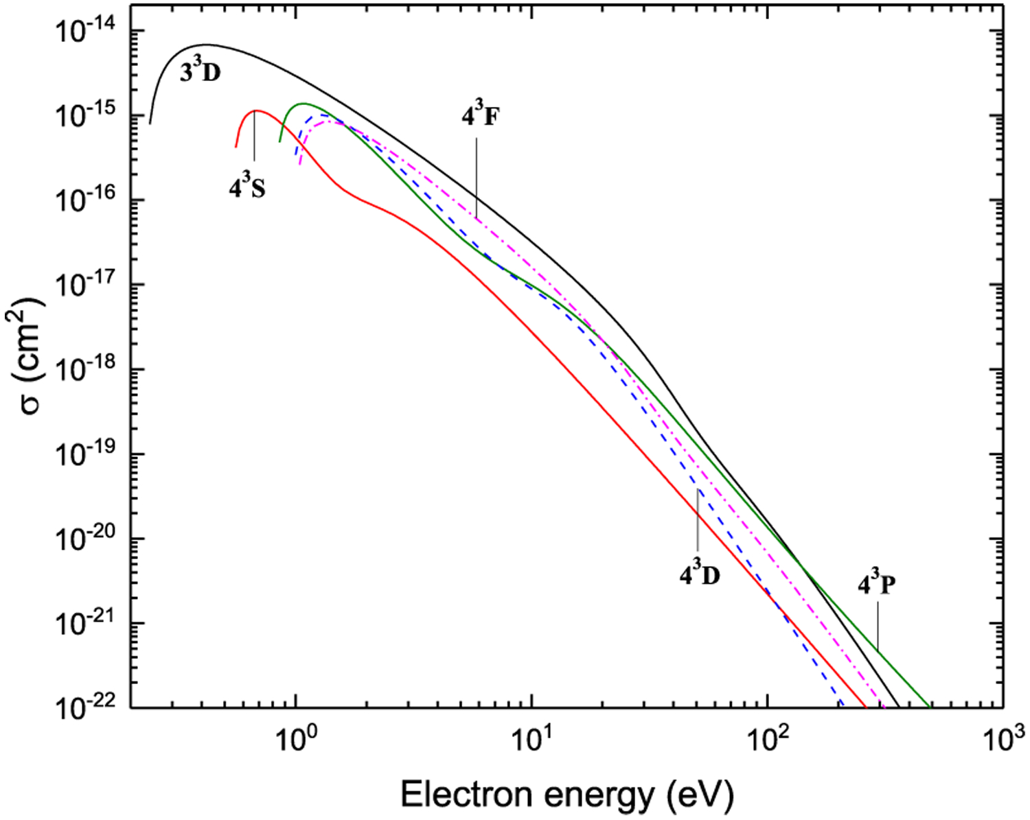
Excitation from 31P
Figure 32:
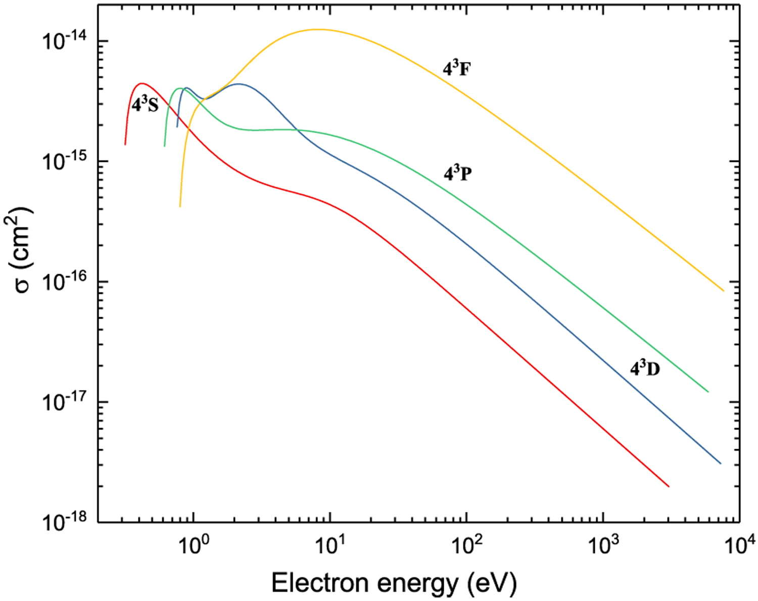
Excitation from 33D
Figure 33:
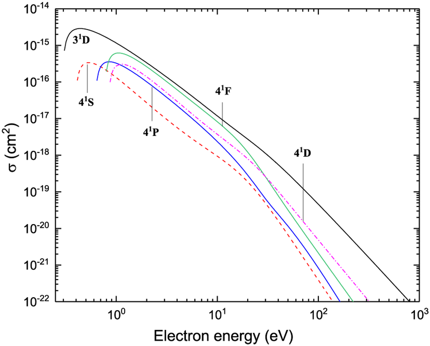
Excitation from 33D
Figure 34:
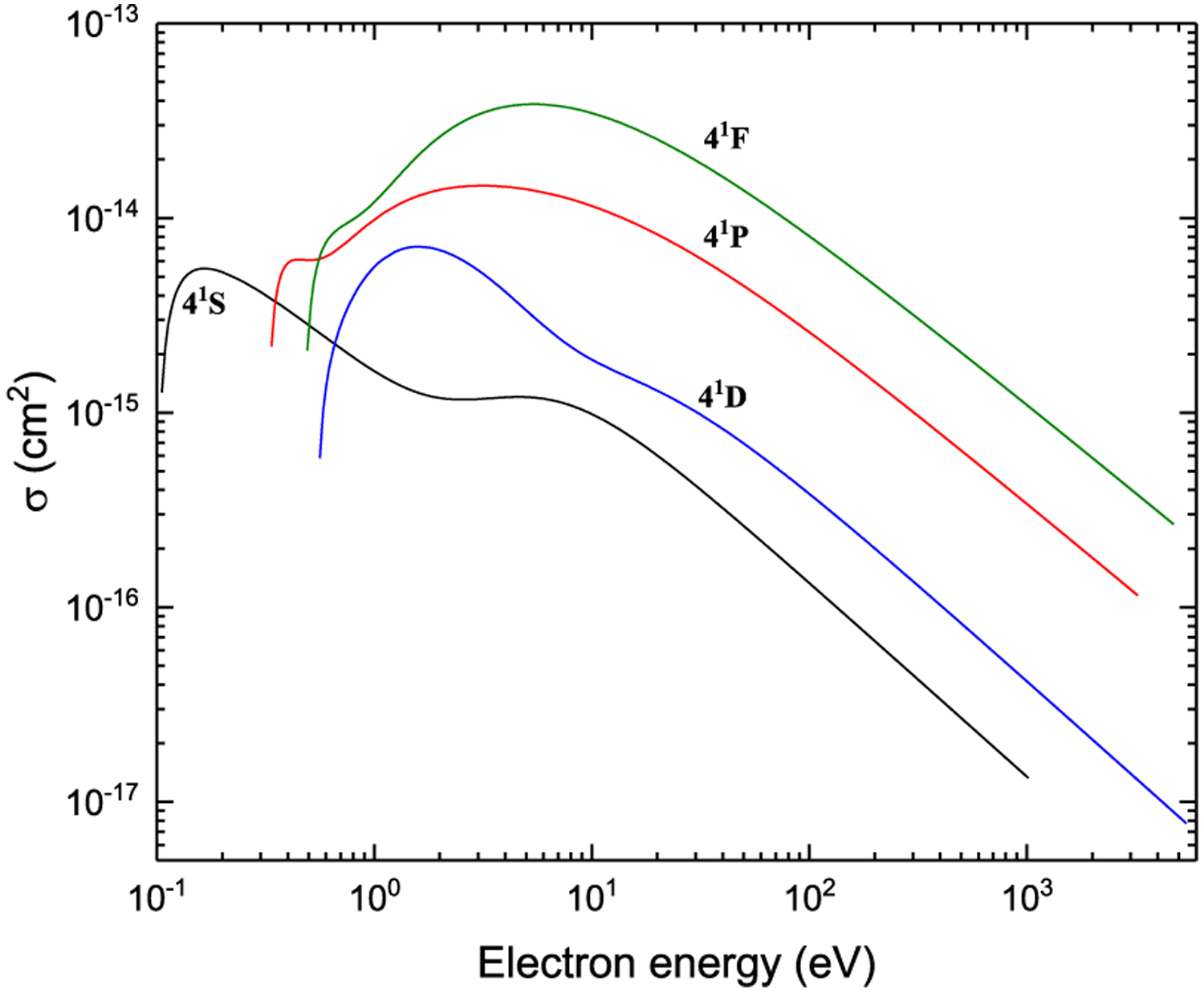
Excitation from 31D
Figure 35:
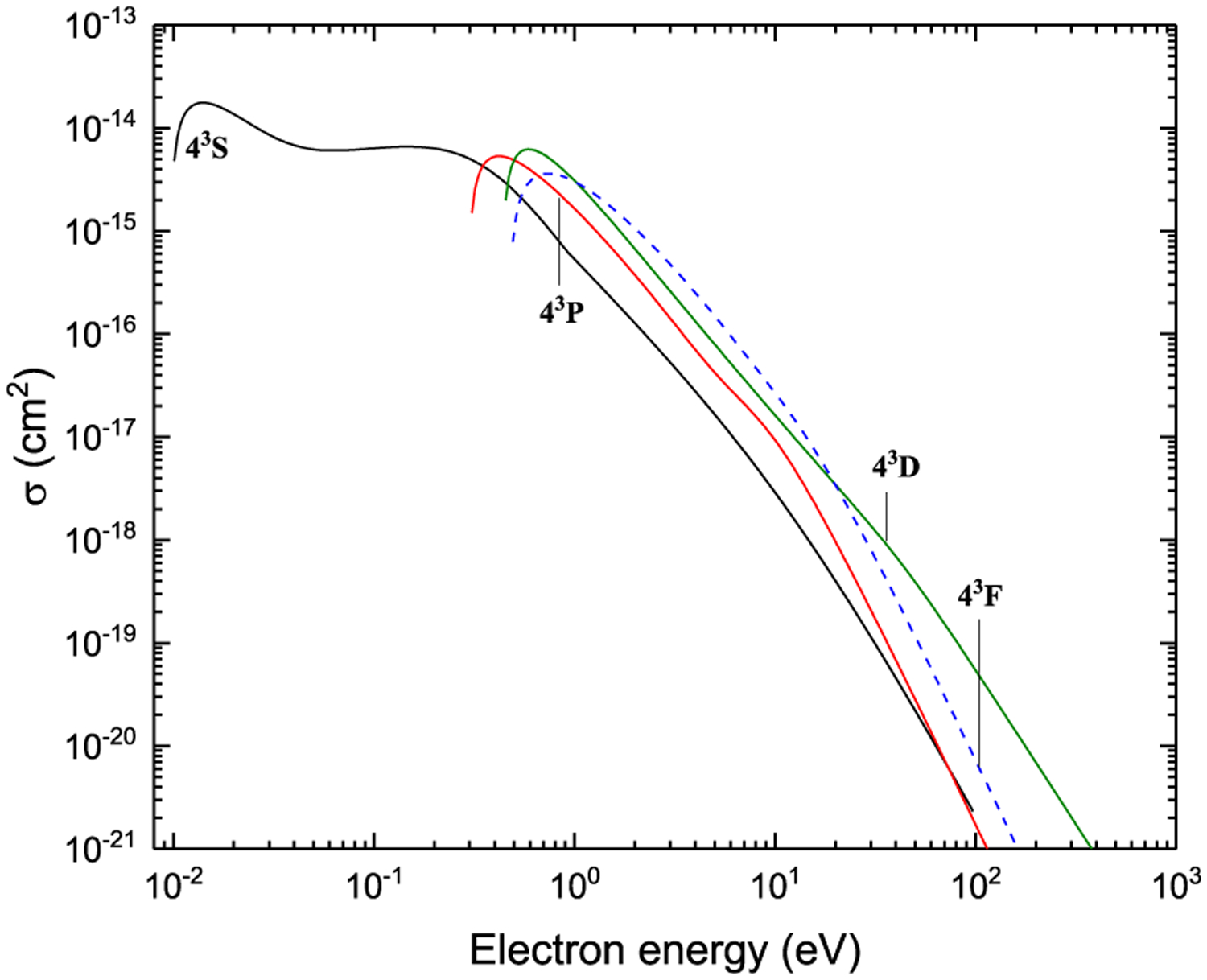
Excitation from 31D
Figure 36:
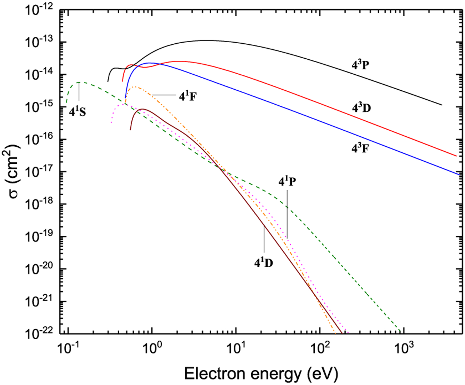
Excitation from 43S
Figure 37:
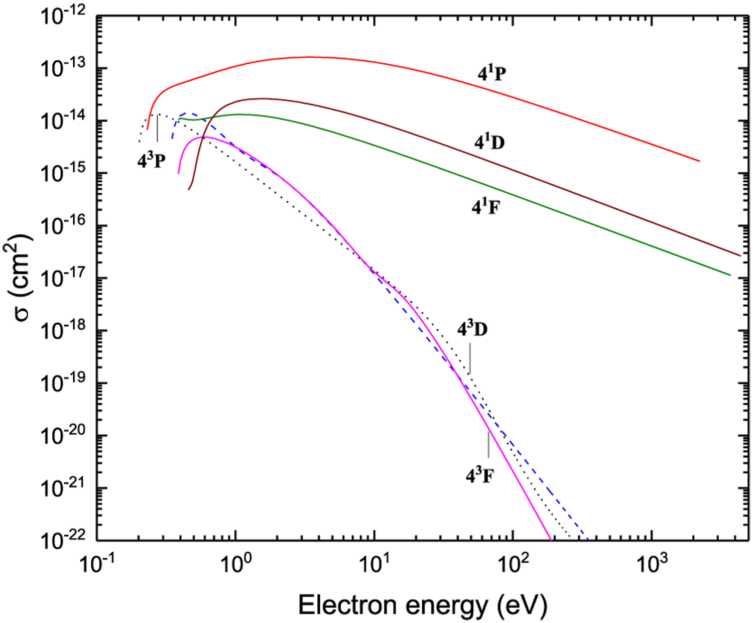
Excitation from 41S
Figure 38:
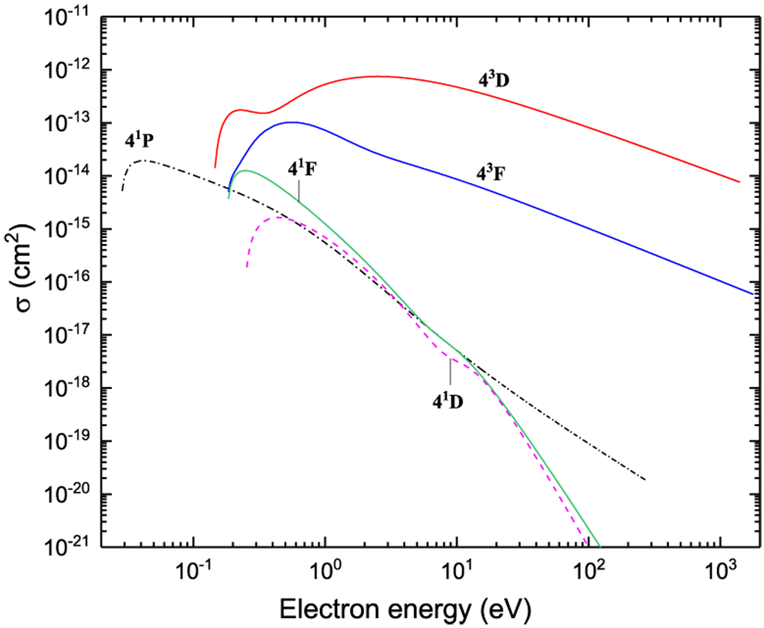
Excitation from 43P
Figure 39:
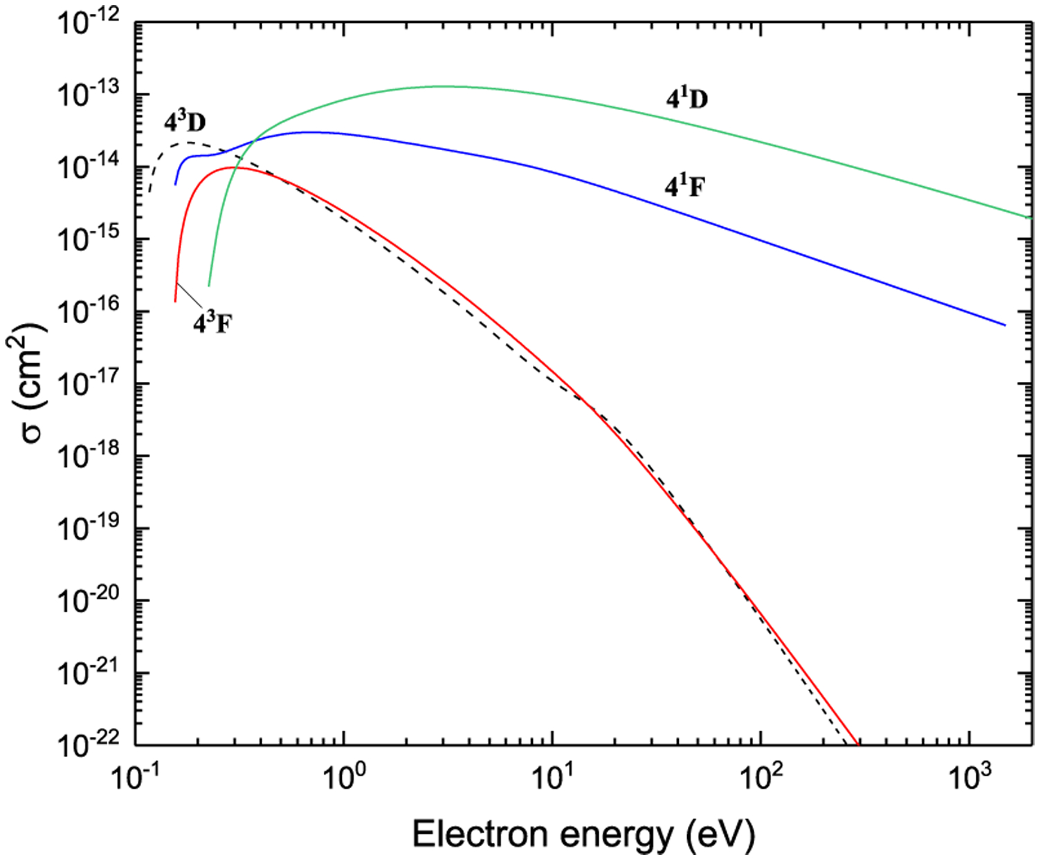
Excitation from 41P
Figure 40:
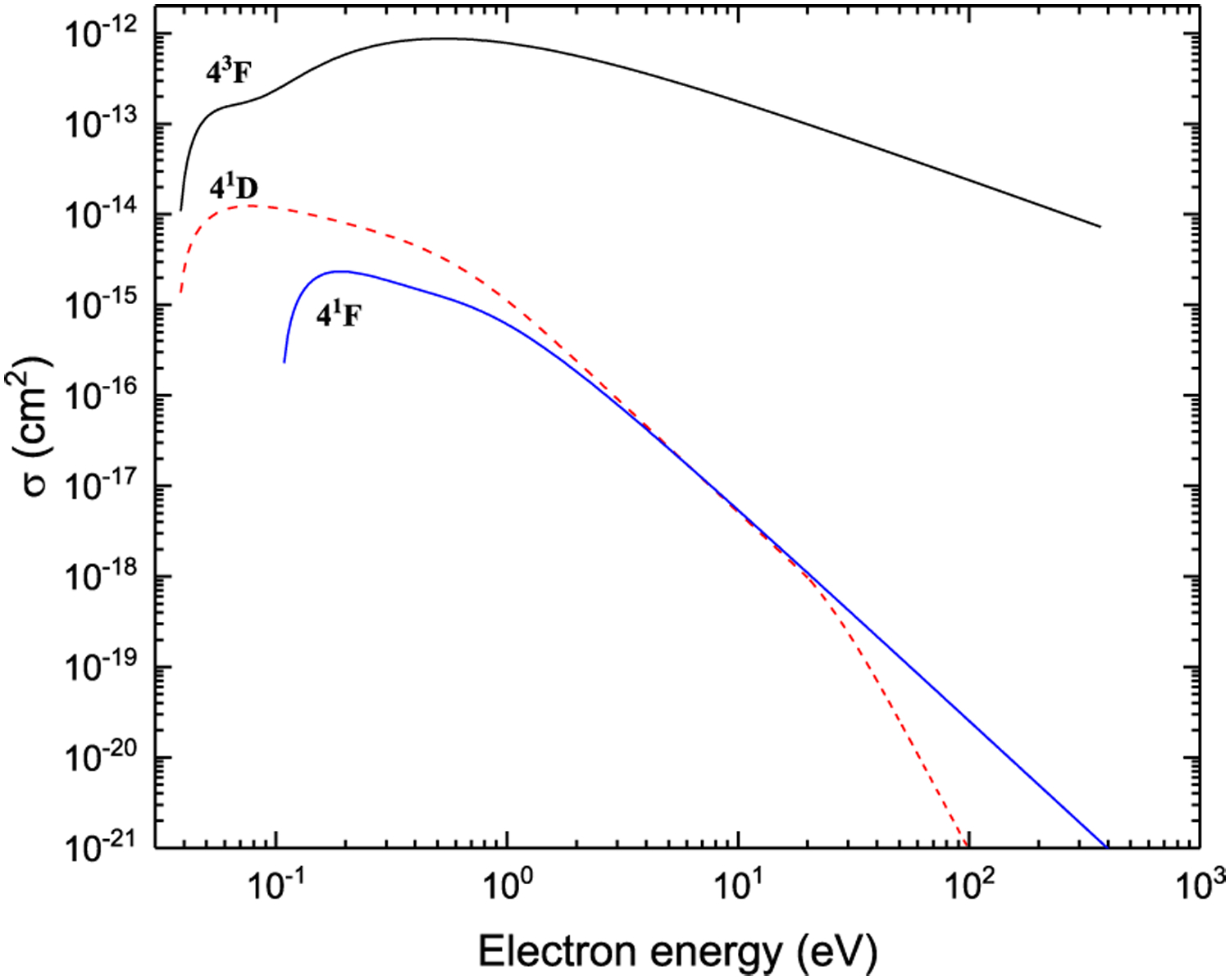
Excitation from 43D
Figure 41:
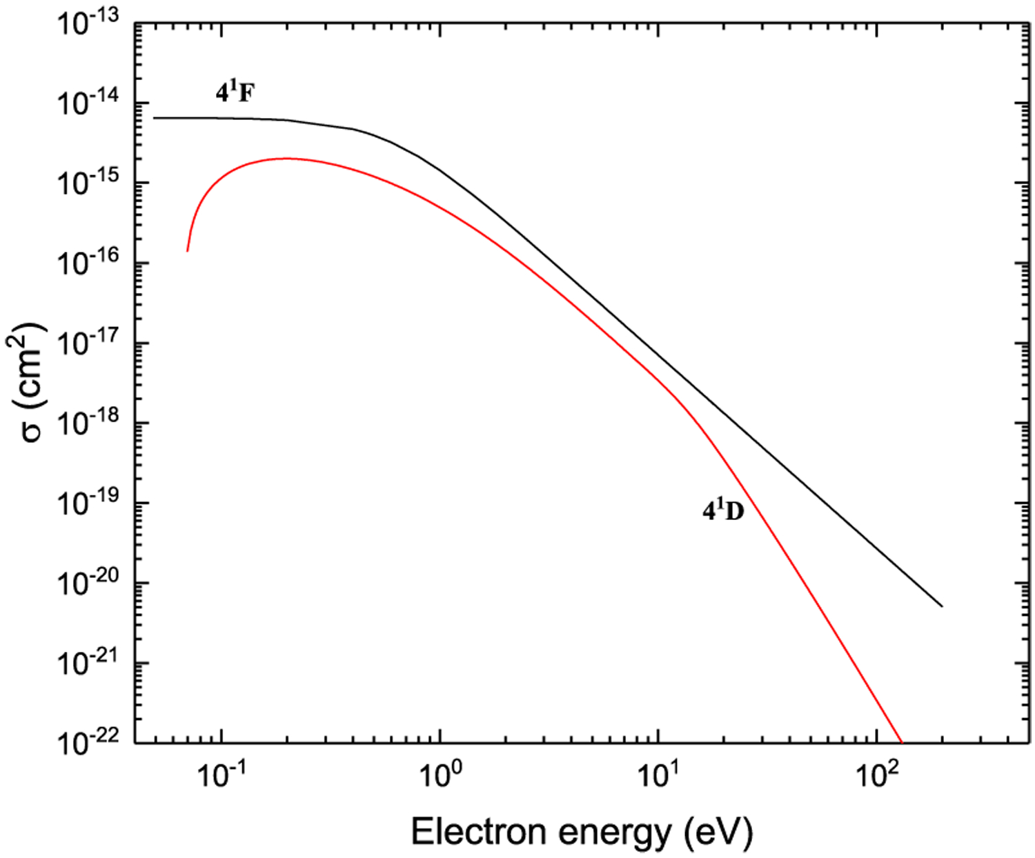
Excitation from 43F
Figure 42:
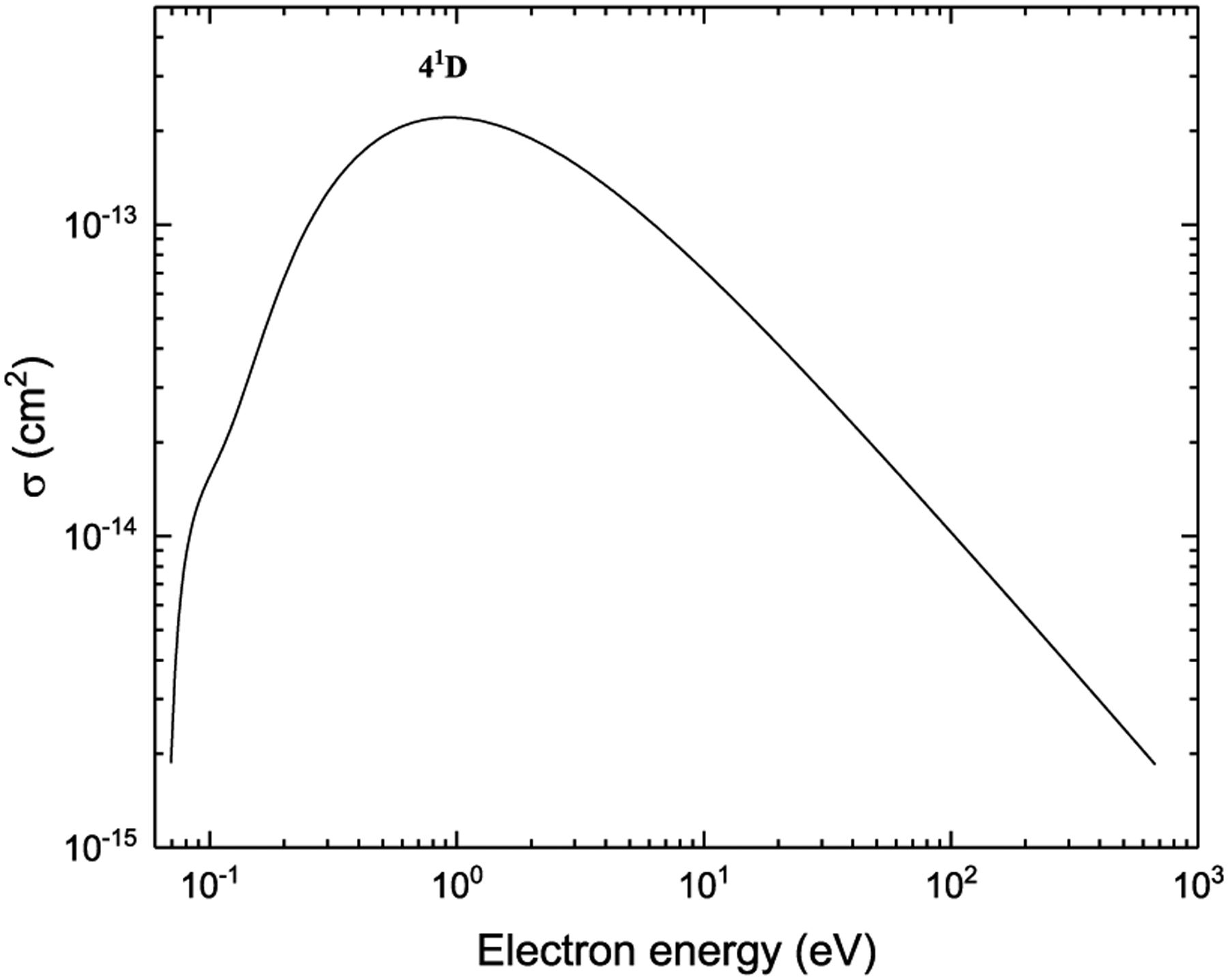
Excitation from 41F
Figures 43–48. Recommended electron-impact ionization cross sections from 2snl (n ≤ 4) and 2p2 terms.
Figure 43:
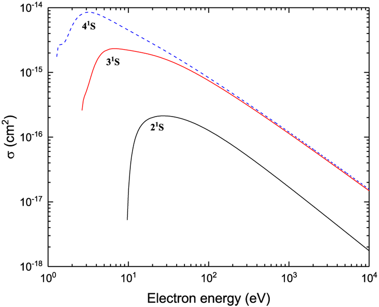
Ionization from n1S
Figure 44:
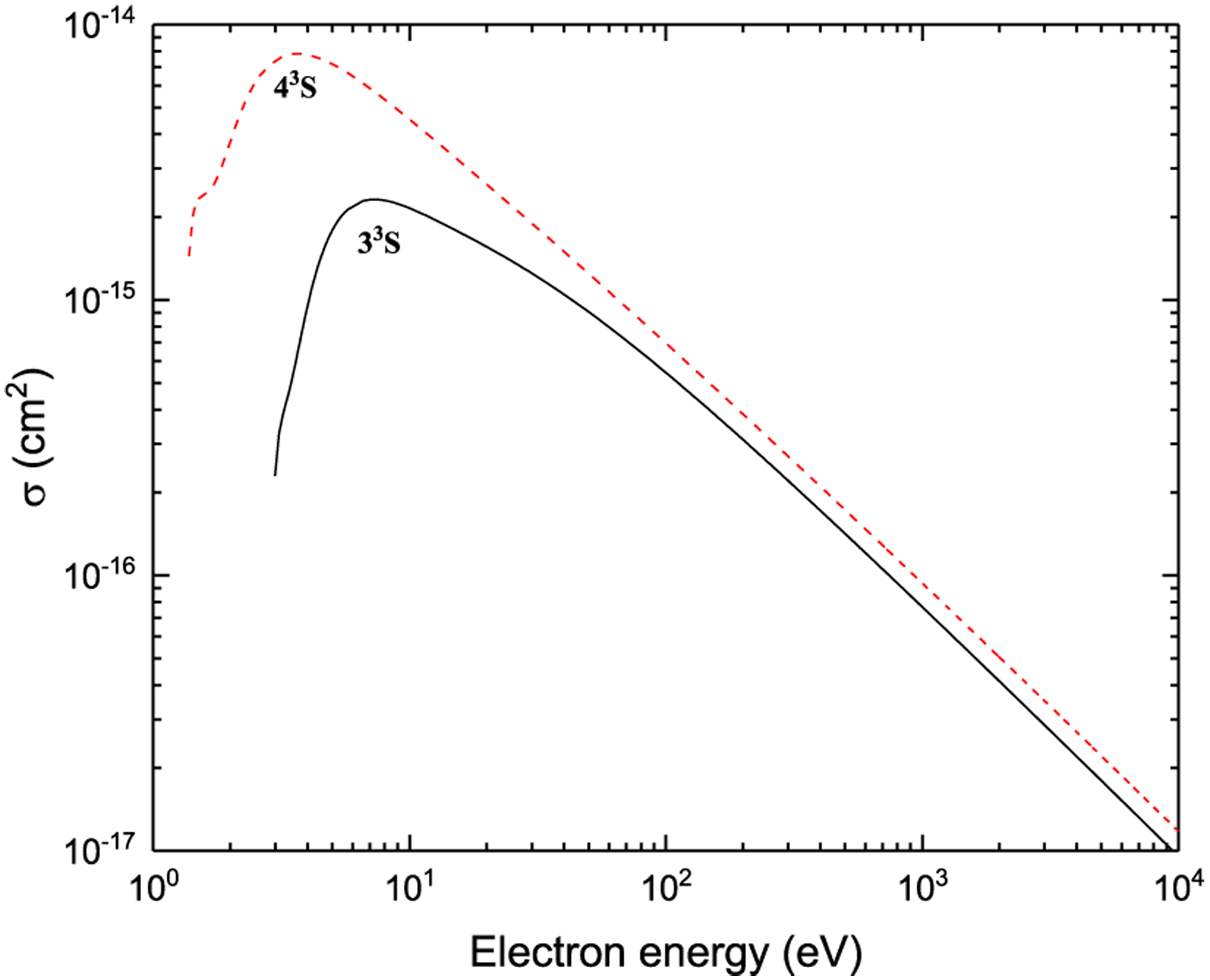
Ionization from n3S
Figure 45:
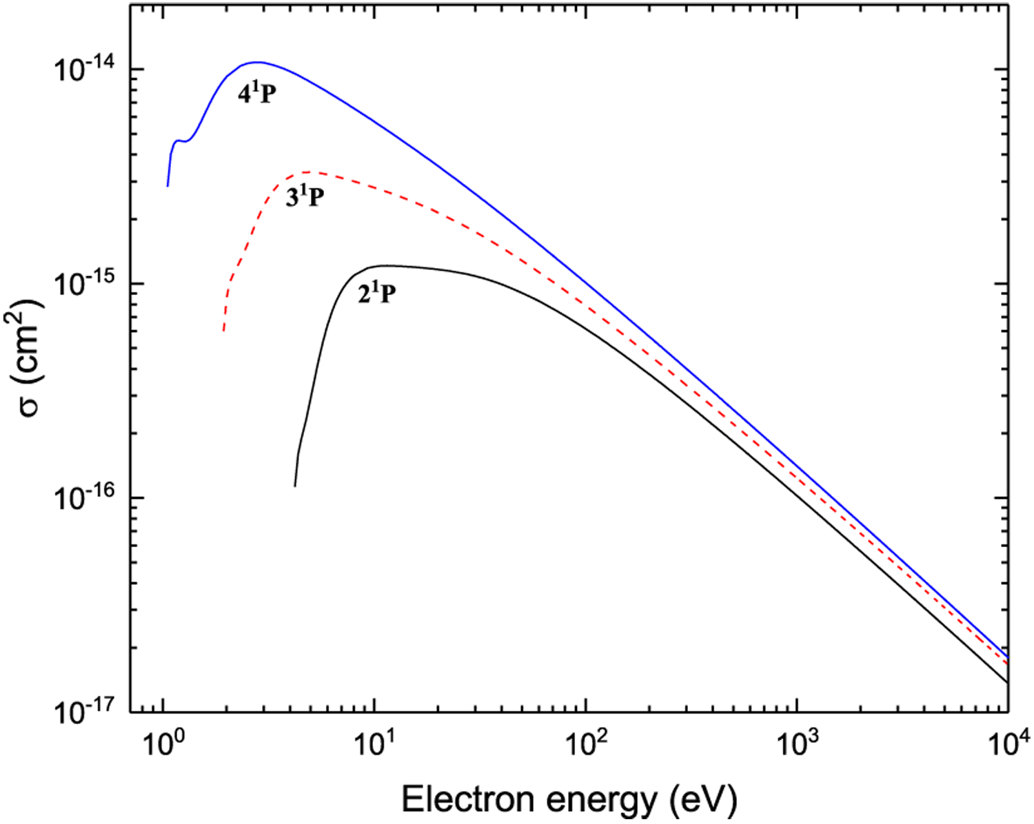
Ionization from n1P
Figure 46:
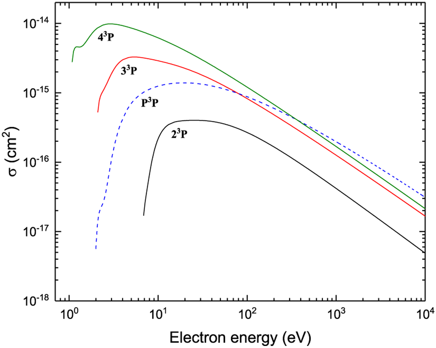
Ionization from n3P and P3P
Figure 47:
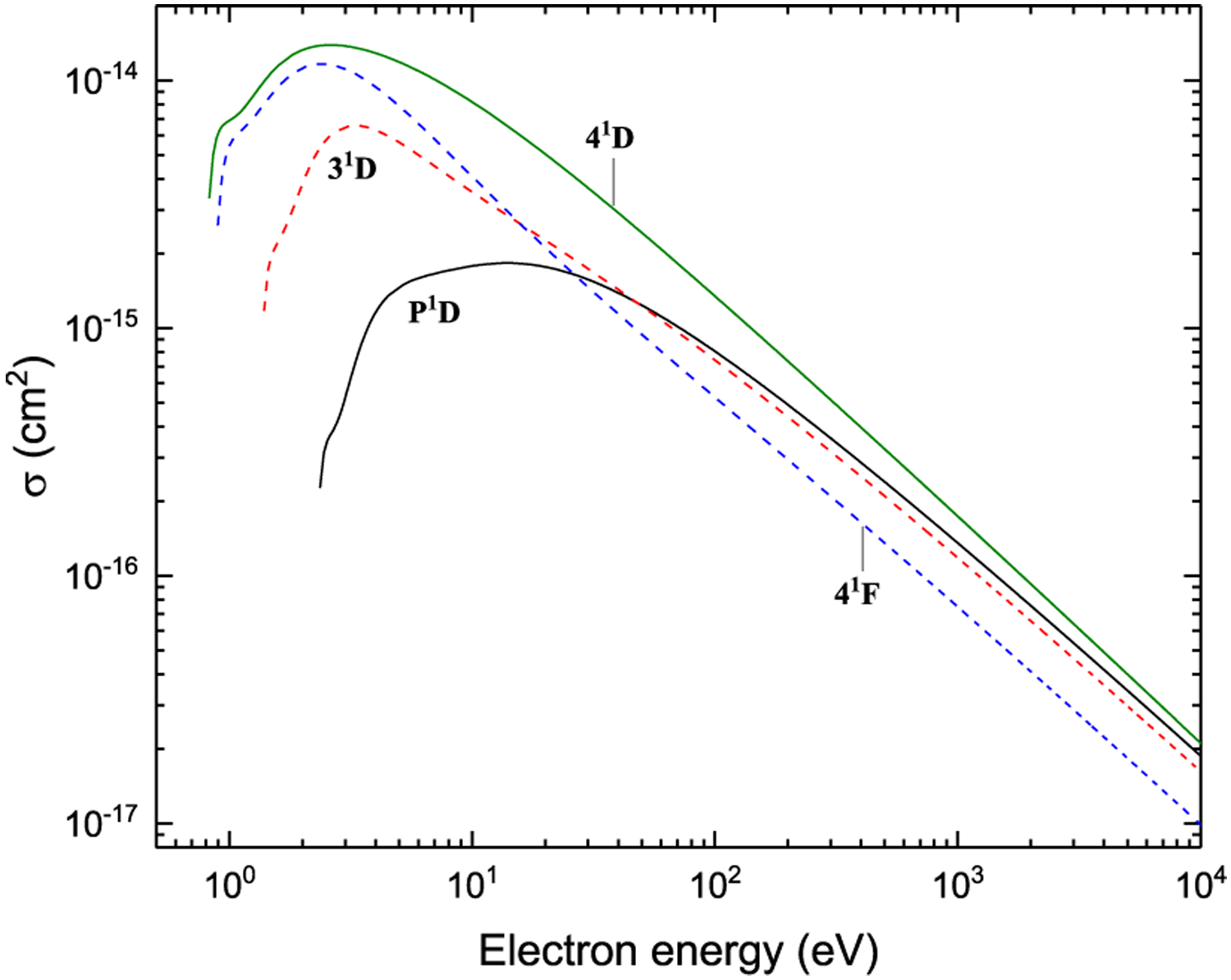
Ionization from n1D, P1D and 41F
Figure 48:
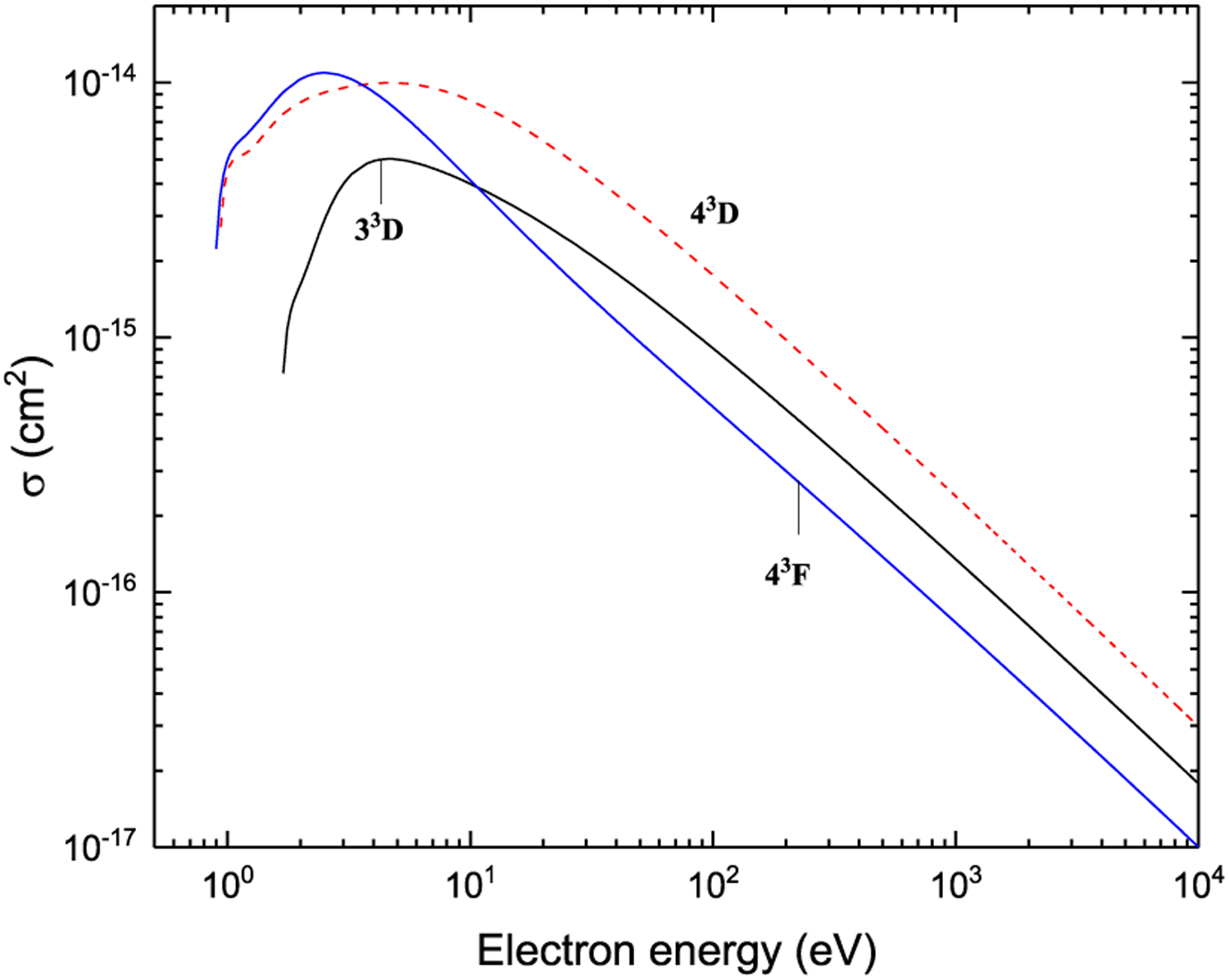
Ionization from n3D and 43F
Figs. 43–48. Recommended electron-impact ionization cross sections from 2snl (n ≤ 4) and 2p2 terms in Be I.
Table 4.
Fitting coefficients in Eq. (7) for electron-impact collision strengths for dipole-forbidden transitions. See explanation of Tables.
| i | f | A0 | A1 | A2 | A3 | A4 | A5 |
|---|---|---|---|---|---|---|---|
| 21S | 31S | −9.947[−01] | 1.311[+00] | −5.716[+00] | 1.491[+01] | −1.609[+01] | 5.729[+00] |
| P1D | −9.899[−01] | 3.798[+00] | −1.815[+01] | 5.682[+01] | −7.308[+01] | 3.104[+01] | |
| 31D | −9.979[−01] | 6.209[−02] | 1.875[+00] | −3.485[+00] | 8.006[−01] | 8.741[−01] | |
| 41S | −9.980[−01] | 3.083[−01] | −1.074[+00] | 2.490[+00] | −2.615[+00] | 9.781[−01] | |
| 41D | 9.195[+00] | 6.174[−02] | 5.900[−01] | 6.950[+00] | −2.233[+01] | 1.890[+01] | |
| 23P | 33P | −9.806[−01] | 1.207[+01] | −3.241[+01] | 8.416[+01] | −1.091[+02] | 5.238[+01] |
| 43P | −9.931[−01] | 3.128[+00] | −1.204[+01] | 4.099[+01] | −5.720[+01] | 2.723[+01] | |
| 43F | −9.220[−01] | 7.503[−01] | 2.192[+00] | −4.373[+00] | 1.452[−01] | 2.046[+00] | |
| 21P | 31P | −9.594[−01] | 1.168[+01] | −2.927[+01] | 1.211[+02] | −2.151[+02] | 1.191[+02] |
| 41P | −9.941[−01] | 1.482[+00] | −4.116[+00] | 3.312[+01] | −6.272[+01] | 3.332[+01] | |
| 41F | −9.954[−01] | 1.744[+00] | 8.620[+00] | −2.996[+01] | 2.986[+01] | −9.211[+00] | |
| 33S | 33D | −9.982[−01] | 8.535[+01] | −1.846[+02] | 3.194[+02] | −3.037[+02] | 8.712[+01] |
| 43S | −7.153[−01] | 1.872[+01] | −1.249[+02] | 3.826[+02] | −5.027[+02] | 2.530[+02] | |
| 43D | −9.868[−01] | 4.369[+00] | −1.767[+01] | 6.114[+01] | −8.199[+01] | 4.118[+01] | |
| 31S | P1D | 4.927[+02] | 8.475[+00] | −6.220[+01] | 1.553[+03] | −3.923[+03] | 1.175[+04] |
| 31D | −9.998[−01] | 2.616[+01] | −4.841[+01] | 1.931[+00] | 7.598[+01] | −5.545[+01] | |
| 41S | −9.950[−01] | 7.414[+00] | −4.245[+01] | 1.008[+02] | −9.948[+01] | 3.488[+01] | |
| 41D | 7.322[+01] | 2.640[+00] | 8.207[+00] | −3.173[+01] | 2.075[+02] | −7.076[+01] | |
| P1D | 31D | −9.819[−01] | 3.299[+01] | 2.559[+01] | −2.958[+02] | 4.988[+02] | −2.507[+02] |
| 41S | −8.384[−01] | 6.855[−01] | 9.093[+00] | 1.579[+01] | −7.426[+01] | 5.828[+01] | |
| 41D | 9.511[+01] | 3.171[+00] | −4.694[+01] | 9.575[+02] | −7.585[+02] | 1.401[+03] | |
| 33P | P3P | 6.862[+04] | 1.366[−01] | 3.019[+02] | 4.044[+04] | −8.584[+04] | 4.583[+04] |
| 43P | 4.309[+01] | 1.342[+02] | −1.566[+03] | 1.635[+04] | −4.515[+04] | 4.280[+04] | |
| 43F | 7.429[+01] | 1.967[+02] | −3.241[+02] | 2.158[+04] | −4.403[+04] | 3.255[+04] | |
| 31P | 41P | −7.349[−01] | 5.658[+01] | −2.952[+02] | 7.973[+02] | −9.956[+02] | 4.672[+02] |
| 41F | −9.887[−01] | 8.181[+01] | 4.928[+00] | −5.540[+02] | 8.711[+02] | −3.978[+02] | |
| 33D | 43S | 6.131[+02] | 7.535[+01] | 7.918[+01] | 1.160[+04] | −4.607[+03] | 8.290[+04] |
| 43D | 1.477[+01] | 2.808[+02] | −3.131[+03] | 2.537[+04] | −5.692[+04] | 4.285[+04] | |
| 31D | 41S | 2.667[+03] | 5.634[+01] | −5.624[+02] | 2.133[+04] | −5.129[+03] | 2.340[+04] |
| 41D | 2.155[+02] | 1.755[+02] | −2.796[+03] | 4.123[+04] | −6.639[+04] | 3.546[+04] | |
| 43S | 43D | 3.148[−02] | 3.241[+02] | −8.760[+02] | 2.688[+02] | 1.433[+03] | −9.724[+02] |
| 41S | 41D | −4.991[−01] | 9.721[+01] | −2.994[+02] | 5.828[+02] | −7.055[+02] | 3.295[+02] |
| 43P | 43F | 3.673[+01] | 7.823[+02] | −8.100[+03] | 9.622[+04] | −1.896[+05] | 1.078[+05] |
| 41P | 41F | 1.264[+03] | 2.398[+02] | 1.081[+02] | 1.500[+05] | −3.970[+05] | 3.250[+05] |
Acknowledgments
This work was initiated at the IAEA Consultants’ Meeting on Evaluation and Uncertainty Assessment for Be, C, Ne Atomic Data https://www-amdis.iaea.org/meetings/BeCNe2015. The work of OZ and KB was supported by the United States National Science Foundation under grants PHY-1403245, PHY-1520970, and PHY-1803844. The BSR calculations were performed on STAMPEDE at the Texas Advanced Computing Center. They were made possible by the XSEDE allocation PHY-090031. The CCC calculations were performed at the Pawsey Supercomputing Centre with funding from the Australian Government and the Government of Western Australia. The authors would like to thank A. Kramida and E. Stambulchik for valuable comments.
References
- [1]. https://www.iter.org/mach/blanket.
- [2].Pitts RA, Coad JP, Coster DP, Federici G, Fundamenski W, Horacek J, Krieger K, Kukushkin A, Likonen J, Matthews GF, Rubel M, Strachan JD, Plasma Phys. Control. Fusion 47 (2005) B303. [Google Scholar]
- [3].Hirai T, Maier H, Rubel M, Mertens P, Neu R, Gauthier E, Likonen J, Lungu C,Maddaluno G, Matthews G, Mitteau R, Neubauer O, Piazza G, Philipps V, Riccardi B, Ruset C, Uytdenhouwen I, Fusion Eng. Des 82 (2007) 1839. [Google Scholar]
- [4].Rubel M, Coad J, Widdowson A, Matthews G, Esser H, Hirai T, Likonen J, Linke J, Lungu C, Mayer M, Pedrick L, Ruset C, J. Nucl. Mater 438 (2013) S1204. [Google Scholar]
- [5].Pajuste E, Kizane G, Vitins A, Igaune I, Avotina L, Zarins R, Nucl. Mater. Energy 12 (2017) 642. [Google Scholar]
- [6].Kondratyev D, Vainshtein L, Bray I, Fursa D, Ralchenko Yu., Phys. Scr. T 161 (2014) 014007. [Google Scholar]
- [7].Bartschat K, Burke PG, Scott MP, J. Phys. B: At. Mol. Opt. Phys 30 (1997) 5915. [Google Scholar]
- [8].Ballance CP, Griffin DC, Colgan J, Loch SD, Pindzola MS, Phys. Rev. A 68 (2003) 062705. [Google Scholar]
- [9].Colgan J, Loch SD, Pindzola MS, Ballance CP, Griffin DC, Phys. Rev. A 68 (2003) 032712. [Google Scholar]
- [10].Fursa DV, Bray I, J. Phys. B: At. Mol. Opt. Phys 30 (1997) 5895. [Google Scholar]
- [11].Bray I, Fursa DV, Phys. Conf. Ser 576 (2015) 012001. [Google Scholar]
- [12].Zatsarinny O, Bartschat K, Fursa DV, Bray I, J. Phys. B: At. Mol. Opt. Phys 49 (2016) 235701. [Google Scholar]
- [13].Blanco F, da Silva FF, ao Vieira PL, García G, Plasma Sources. Sci. Technol 26 (2017) 085004. [Google Scholar]
- [14].Jönsson P, Gaigalas G, Bieroń J, Fischer CF, Grant I, Comput. Phys. Comm 184 (2013) 2197. [Google Scholar]
- [15].Kramida A, Ralchenko Yu., Reader J, NIST ASD Team 2018. NIST Atomic Spectra Database (ver. 5.5.6), 2018, July https://physics.nist.gov/asd. [Google Scholar]
- [16].Jönsson P, Fischer CF, Godefroid MR, J. Phys. B: At. Mol. Opt. Phys 32 (1999) 1233. [Google Scholar]
- [17].Tachiev G, Fischer CF, J. Phys. B: At. Mol. Opt. Phys 32 (1999) 5805. [Google Scholar]
- [18].Zatsarinny O, Fischer CF, Comput. Phys. Comm 180 (2009) 2041. [Google Scholar]
- [19].Zatsarinny O, Comput. Phys. Comm 174 (2006) 273. [Google Scholar]
- [20].Kramida A, Martin WC, J. Phys. Chem. Ref. Data 26 (1997) 1185. [Google Scholar]
- [21].Fischer CF, Phys. Scr. T 134 (2009) 014019. [Google Scholar]
- [22].Ynnerman A, Fischer CF, Phys. Rev. A 51 (1995) 2020. [DOI] [PubMed] [Google Scholar]
- [23].Kramida A, Fusion Sci. Technol 63 (2013) 313323. [Google Scholar]
- [24].Fursa DV, Bostock CJ, Bray I, Phys. Rev. A 80 (2009) 022717. [Google Scholar]
- [25].van Regemorter H, Astrophys. J (1962) 906. [Google Scholar]
- [26].Kwon D-H, Lee W, Preval S, Balance CP, Behar E, Colgan J, Fontes CJ, Nakano T, Li B, Ding X, Dong CZ, Fu YB, Badnell NR, O’Mullane M, Chung H-K, Braams BJ, At. Data Nucl. Data Tables 119 (2018) 250. [Google Scholar]
- [27].Ralchenko Yu., Janev RK, Kato T, Fursa DV, Bray I, de Heer FJ, At. Data Nucl. Data Tables 94 (2008) 603. [Google Scholar]


