SUMMARY:
Head and neck surgical reconstruction is complex, and postoperative imaging interpretation is challenging. Surgeons now use microvascular free tissue transfer, also known as free flaps, more frequently in head and neck reconstruction than ever before. Thus, an understanding of free flaps, their expected appearance on cross-sectional imaging, and their associated complications (including tumor recurrence) is crucial for the interpreting radiologist. Despite the complexity and increasing frequency of free flap reconstruction, there is no comprehensive head and neck resource intended for the radiologist. We hope that this image-rich review will fill that void and serve as a go to reference for radiologists interpreting imaging of surgical free flaps in head and neck reconstruction.
Surgical free flaps (FFs) have become the preferred reconstruction method for most large head and neck (H&N) oncologic defects. They have better functional outcomes and cosmetic restoration than surgical grafts and other types of surgical flaps (local and regional).1–4 Since free flaps were first used in the 1970s, surgeons have expanded their repertoire, fine-tuned techniques, and improved outcomes.5 While FFs may be used to reconstruct defects from infection, trauma, and osteonecrosis, they are most often used following tumor extirpation. FFs are unfortunately frequent today as >675,000 patients worldwide are diagnosed with H&N cancer annually.6
Posttreatment H&N clinical and imaging follow-up is complex, even more so when the resection site is reconstructed. To provide accurate and useful H&N imaging reports, radiologists should have a basic understanding of the surgical options, ranging from skin grafts to surgical flaps. This review article focuses on free flaps, summarizing what defines an FF, those most commonly used, the expected postoperative imaging appearances, and associated complications.
Flap Versus Graft
Surgical flaps and surgical grafts are both used in H&N reconstruction. While the 2 are distinct entities, it is not uncommon to hear them incorrectly used interchangeably. Both are blocks of transferred tissue, but flaps have their own blood supply while grafts depend on angiogenesis.5,7 Surgical flaps are transferred either with an intact vascular supply or the blood supply is re-established at the recipient site using microvascular techniques. Conversely, the major graft vasculature is transected at the donor site and the tissue inset without vessel-to-vessel anastomosis.
Grafts may be autograft (from the patient), allograft (from a donor, often cadaveric), or alloplastic (man-made). Grafts are typically 1 or 2 tissue types, whereas surgical flaps are often more complex and contain several different tissue constituents. The most commonly used grafts in H&N reconstruction are the fairly straightforward skin grafts, which can be full thickness (complete segments of both epidermis and dermis) or split thickness (complete epidermis but incomplete varying-thickness dermis).7,8 Bone grafts continue to be used for certain craniofacial and spine reconstructive procedures.9 Often for large-volume composite defects of the head and neck, flaps are superior to grafts with respect to cosmesis because the bulk of flap tissue better fills defects and maintains its size and shape for the duration of the patient's life. Flaps also typically heal better, in a quicker and more predictable fashion with less contracture than grafts in the head and neck.10,11
Flap Types
Surgical flaps are typically classified by their pattern of vascularity and their proximity to the primary defect. In terms of blood supply, flaps can be typified as random or axial.5,7,12,13 Random flaps are supplied by the subdermal plexus of the skin and are not supplied by distinct named vessels. In contrast, axial flaps are supplied by a specific arteriovenous system. Axial flaps are typically considered more reliable than random flaps on the basis of improved distal perfusion.
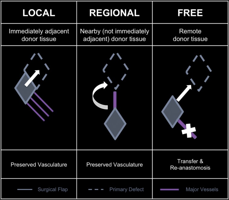
With respect to defect proximity, flaps can be classified as local, regional, or free (Fig 1). Local flaps, flaps generated adjacent to the primary defect, are examples of random flaps. Examples of local flaps include rotation, advancement, and transposition. Regional and free flaps typically have axial-based vascularity, wherein these flaps are dependent on a specific vascular pedicle for viability. An example of a regional flap is the pectoralis major myocutaneous flap, supplied by the pectoral branch of the thoracoacromial artery. Free tissue flaps are the most complex and technically challenging form of flap reconstruction. Each free flap is designed and harvested at a spatially distinct site from the primary defect known as the donor or harvest site. Each donor vascular pedicle is transected at the donor site, transferred along with the flap constituents to the primary defect, and inset at the primary defect. Then, with microsurgical techniques, the donor pedicle is anastomosed to the recipient vessels near the defect to re-establish the blood supply to the flap.5,7,12,13
Fig 1.
Flaps based on donor location with respect to the primary defect.
An additional distinction with regional and free flaps is that they may be of simple or composite design. A simple flap is typically composed of skin and subcutaneous tissue. Composite flaps, like composite resection sites, can consist of multiple tissue types and often include bone and/or muscle.5,7,13
The decision of which flap to use is made on an individual case basis because some flap types are advantageous over others for certain patients, tumors, and reconstruction locations. For example, in patients with tongue reconstruction following glossectomy, those with FFs had superior speech intelligibility compared with those with pedicle flaps.3,4
Free Flap Types
Surgeons innovatively use a wide variety of surgical free flaps (Table 1).14 Most surgeons approach FF reconstruction by giving consideration to the oncologic surgical defect, the donor sites available, surgeon preference, and the available hospital and surgical resources (Table 2).13,15,16 Because there is no “one size fits all” approach, the number and complexity of the many different types of surgical FFs are vast and can be overwhelming. Thus, for radiologists, it is useful to categorize free flaps by the dominant donor tissue constituents (Table 1), creating 4 main categories: muscular, fascial, osseous, and visceral FFs.17
Table 1:
Surgical free flaps in head and neck reconstruction
| Category | Free Flap | Reconstructs | Donor Artery |
|---|---|---|---|
| Muscular | Rectus abdominis | Skull base, orbit | Deep inferior epigastric |
| Latissimus dorsi | Skull base, scalp | Thoracodorsal | |
| Fascial | Radial forearm | Oral cavity, tongue, palate, nose, face, scalp, lip, pharynx, larynx | Radial |
| Ulnar forearm | Oral cavity, tongue, palate, nose, face, scalp, lip, pharynx, larynx, cervical esophagus | Ulnar | |
| Lateral thigh | Oral cavity, tongue, palate, pharynx | Deep femoral | |
| Anterolateral thigh | Oral cavity, tongue, palate, pharynx, larynx, cervical esophagus | Descending branch, lateral circumflex femoral | |
| Scapula | Oral cavity, tongue, palate, nose, face, lip | Subscapular | |
| Osseous | Fibula | Mandible | Peroneal |
| Radius | Mandible & midface | Radial | |
| Scapula | Mandible & midface | Subscapular, thoracodorsal | |
| Iliac crest | Mandible & midface | Deep circumflex | |
| Visceral | Jejunum | Pharynx, esophagus | Superior mesenteric branches |
| Omentum | Scalp | Gastroepiploic |
Table 2:
Surgical approach to free flaps in H&N reconstruction
| Factor | Question | Limitation |
|---|---|---|
| Defect | What needs to be replaced? | Constituents |
| Function | ||
| Size | ||
| Donor | What is available? | Body habitus |
| Vascular integrity | ||
| Vascular anomalies | ||
| Surgeon | What can be done? | Skills |
| Support |
This simplified approach has important facts to note. Although we are grouping these by the dominant tissue type, most of these FFs also contain skin paddles that reconstruct both skin and mucosal surfaces because both should be reformed with epithelial tissue. Additionally, some FFs (rectus abdominis and latissimus dorsi) may be harvested as either myocutaneous or fasciocutaneous. Last, there is a subset of free flaps referred to as perforator flaps, defined by the surgical isolation of the small vessels perforating the muscles at the donor site, sparing the larger donor vessel and resulting in improved donor site morbidity but shorter FF vascular pedicles.18
Muscular.
Muscle-containing FFs in H&N reconstruction are mostly myocutaneous (or musculocutaneous), composed of both muscle and skin as well as the adjacent subcutaneous tissue, vessels, and fascia. This category of FF is particularly useful to fill large defects (Fig 2), including skull base defects.7,19 Two of the more commonly used myocutaneous FFs are the rectus abdominis and latissimus dorsi muscle FFs.
Fig 2.
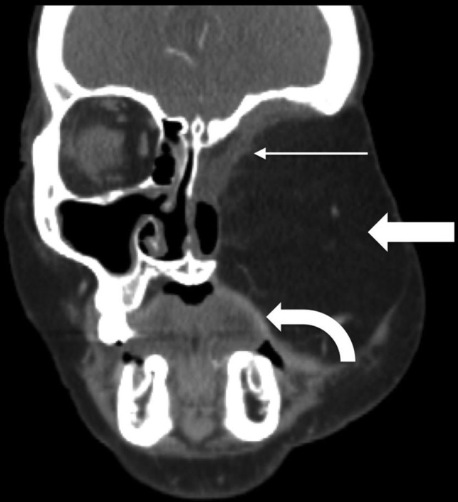
Rectus abdominis FF. Postoperative coronal CECT in a patient with T4bN0M0 basaloid carcinoma and recurrence after initial partial maxillectomy demonstrates the bulky rectus abdominis FF (block arrow) filling the left midface defect following orbital exenteration and total maxillectomy. The rectus muscle (thin arrow) lines the skull base defect, while a portion of the skin paddle recreates the oral cavity mucosal surface (curved arrow).
Rectus abdominis FFs include one of the paired vertically oriented ventral abdominal muscles.5,20 They are especially advantageous because of the versatility of flap design and the length of the associated vascular pedicle, up to 10–15 cm long. This vascular pedicle length allows the surgeon to inset rectus FFs into almost any H&N defect, even those a distance away or on the opposite side of the head and neck from the vascular anastomoses. As with most cutaneous FFs, the skin paddle recreates the skin surface and mucosal surface (Fig 2). One drawback is that the thickness of the FF is particularly reflective of a patient's weight and may prove too bulky for some resection cavities in obese patients due to excessive subcutaneous fat.5 Rectus abdominis FFs can also be harvested as fasciocutaneous free flaps.
Latissimus dorsi FFs are the largest muscle flaps, with a total area measuring up to 25 × 40 cm. However, the muscle itself is one of the thinnest in the body. The latissimus spans from the posterolateral thorax to the inferomedial back (Fig 3). Like rectus FFs, they can fill large defects. One or 2 skin paddles may be harvested, allowing a variety of uses, such as floor of mouth reconstruction (Fig 3) or large skull base defects.5,7
Fig 3.
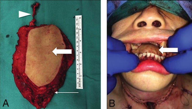
Latissimus dorsi FF. Following total glossectomy, right oropharyngectomy, and total laryngectomy for T4a squamous cell carcinoma (SCC) of the right oral tongue, the FF was harvested and set on the operating room back table (A) with the elongated vascular pedicle (arrowhead), skin (block arrow), and latissimus (arrow). The latissimus is fastened to secure the mandible and recreate the mylohyoid sling. Immediate postoperative picture (B) shows the skin paddle (block arrow) closing the glossectomy defect.
Fascial.
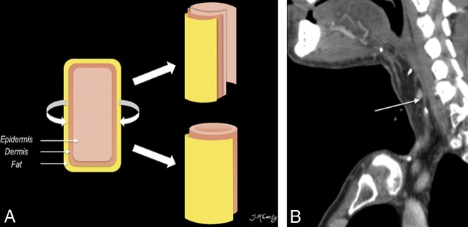
Fascia-containing FFs in H&N are nearly exclusively fasciocutaneous, including a skin paddle in addition to the fascia, vessels, and subcutaneous tissue. Fasciocutaneous FFs can be used to restore skin or mucosal defects (Fig 4). Additionally, fasciocutaneous FFs can be tubed/rolled to recreate epithelial-lined conduits (Fig 5).5,7,21 Two of the more commonly used fasciocutaneous FFs are the radial forearm and anterolateral thigh FFs.
Fig 4.
Radial forearm FF. Intraoperative photo (A) shows the radial artery (arrows) up to the skin paddle (asterisk) after Doppler mapping. Postoperative clinical picture (B) demonstrates the well-incorporated mature flap (double asterisks) following marginal mandibulectomy.
Fig 5.
Tubed radial forearm FF. The diagram (A) shows that free flaps can be partially rolled (upper right) or completed tubed (lower right) to reconstruct the upper aerodigestive tract. Postoperative sagittal CECT (B) following base of tongue hemiglossectomy and laryngopharyngectomy shows the radial forearm FF reconstruction (long arrow).
The radial forearm FF has a rich vascular supply and may be harvested in a variety of sizes. It has been used more extensively and for a wider variety of reconstructions than any other flap.5 This FF is particularly advantageous because the forearm skin is usually non-hair-bearing and the forearm is least influenced by obesity.7 Primary indications for use include reconstruction of skin or mucosal lining defects, partial/hemiglossectomy defects, and pharyngeal defects. The radial forearm FF is harvested from the volar aspect of the forearm and includes the radial artery (Fig 4). Thus, performing an accurate preoperative Allen test is of the utmost importance to ensure an adequate supply of the hand via the ulnar artery and to avoid catastrophic ischemia of the hand.5
The anterolateral thigh (ALT) FF has a large, thin, pliable skin paddle and a long vascular pedicle, up to 15 cm. Similar to the radial forearm FF, ALT reconstruction can be used for skin and mucosal lining defects, subtotal glossectomy defects (Fig 6), pharyngeal defects, and skull base defects. This FF can be tubed for pharyngoesophageal defects. Because the ALT FF is harvested from the anterior and proximal aspect of the lower extremity, there is relatively little morbidity at the donor site and the patient's clothing typically covers any postoperative scarring.5,7
Fig 6.
Anterolateral thigh FF. Axial fat-saturated T1 postcontrast MR imaging (A) demonstrates the T4a left lateral oral tongue SCC (asterisk), which also involved the extrinsic tongue muscles and floor of mouth. Line drawing (B) of the ALT donor site (outlined) axial anatomy includes the descending branch of the lateral circumflex femoral artery. The ALT has a large, thin, pliable skin paddle with relatively little morbidity at the donor site. ALT FF intraoperative image (C) shows the harvested FF on the operating room back table with an elongated vascular pedicle (arrowhead). Postoperative axial CECT (D), obtained 12 weeks after the operation, shows the inset homogeneous fatty tongue ALT FF (arrow) without induration or edema. The recipient site margins (short arrow) have no nodularity.
Osseous.
Osseous-containing FFs are some of the most complex FFs. They are mostly composite flaps, containing multiple different tissue types in addition to bone, including skin, subcutaneous tissue, fascia, and muscle (Fig 7). One of the surgical goals is to “replace like with like,” meaning reconstructing surgical cavities with tissue constituents similar to those resected. Thus, osteocutaneous FFs have become popular solutions for many maxillary and mandibular defects.5 Long segments of bone, up to 25 cm, may be harvested and crafted as a variety of surgical constructs using surgical plates and screws. Two of the most commonly used osteocutaneous FFs are the fibular and scapular FFs.
Fig 7.
Fibular FF. Preoperative 3D-volume rendered CT (A) demonstrates the T4aN0 right oral cavity SCC (asterisk). Intraoperative photograph (B) (different patient but with a similar reconstruction) shows the surgical plate and bicortical screws used to fixate the inset fibular flap (arrowheads) to the residual native mandible (block arrows). Postoperative 3D-volume rendered CT (C) demonstrates the fibular FF reconstruction (thin arrow) following the right segmental mandibulectomy.
The tubular shape and thick cortical bone make the fibular FF particularly strong. This can be harvested with skin (free osteocutaneous) or without (free osseous). Up to 25 cm of the fibula may be resected with little effect on the gait as the fibula is a non-weight-bearing bone. The fibular FF is most commonly used for mandibular reconstruction (Fig 7). Most importantly preoperative evaluation must ensure that the peroneal artery does not supply the foot because this is the main supplying artery of the FF and will lead to foot ischemia if harvested.5,22
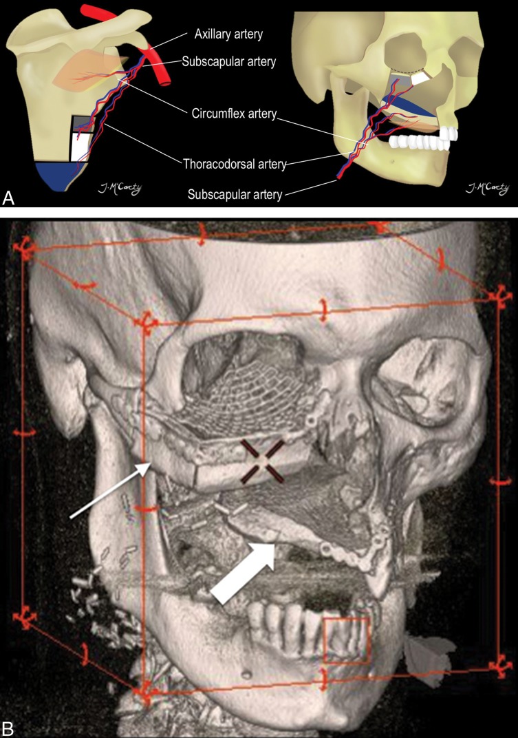
The scapular osteocutaneous FF has become a more popular option for complex midface reconstructions (Fig 8). The vascular pedicle is long, up to 14 cm, and the vessel diameters are large, 3–4.5 mm. Different segments of the bone can be harvested, including the scapular tip and up to 2 segments of the lateral border. Any of the segments can be fashioned to reconstruct the hard palate or orbital rim. One or 2 skin paddles can be obtained; unfortunately, they are often hair-bearing in male patients, resulting in an undesired postoperative cosmetic appearance if used in certain locations (ie, oral cavity mucosal reconstruction). The scapular skin paddles are particularly advantageous because they can be completely separate from the osseous component, providing the most freedom for 3D insetting of any composite FF.5,7
Fig 8.
Scapular osteocutaneous FF. A, Diagram of the scapular donor site (left) and midface inset (right) demonstrates the versatile scapular osteocutaneous FF for complex midface defects. A variety of different bone shapes can be obtained depending on the contour of the defect. One or 2 skin paddles may be harvested; one usually recreates the oral mucosal surface as shown in the diagram. 3D-volume rendered CT (B) in a patient who is status post right maxillectomy shows the lateral scapular border reconstructing the right maxilla and orbital rim (thin arrow), while the scapular tip reconstructs the hard palate (block arrow).
Visceral.
Visceral FFs can be used in pharyngoesophageal reconstruction. The jejunal FF is especially useful given its similar in caliber to the esophagus (Fig 9).16 The pharynx is a larger caliber than the jejunal FF; thus, the cephalad border of the flap may be opened along the antimesenteric border to achieve a more suitable anastomosis.5 For circumferential pharyngeal defects, jejunal and ALT FFs have slightly better functional outcomes than radial forearm FFs.23
Fig 9.
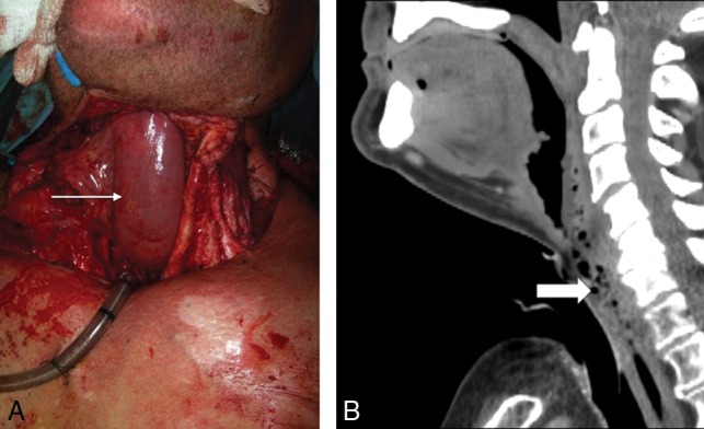
Jejunal FF. Following laryngopharyngectomy, the intraoperative photograph (A) shows a segment of the jejunum (arrow) interposed between the oropharynx and esophagus, anastomosed end to end to allow patients to eat and swallow. Sagittal postoperative CECT (B) shows the jejunal FF neopharynx (block arrow).
Radiologic Evaluation following FF Reconstruction
Preoperative imaging should always be reviewed when the posttreatment scan is interpreted as it helps to understand what anatomic structures were resected and where the primary tumor was located. The CT or MR imaging appearance of the FF reconstruction reflects the flap components.
CT should always be performed with intravenous contrast administered in a standard amount and timing of the acquisition so that serial or surveillance scans can be compared. In our practice, the first posttreatment contrast-enhanced CT (CECT) is performed with PET to increase detection of persistent tumor, nodal, or distant metastases and to differentiate residual tumor from non-neoplastic postoperative changes. Imaging protocols include combined PET/CT from the skull vertex through the midthigh 1 hour after intravenous administration of 10–14 mCi of FDG. Helical noncontrast CT is performed before PET for attenuation correction and anatomic localization. A CECT of the neck with the arms down is performed following PET, using a split-bolus technique with 110 mL of intravenous iopamidol (Isovue-370; Bracco, Princeton, New Jersey), with 55 mL injected first at 2.5 mL/s, a 40-second delay, then another 55 mL at the same rate, and a total scan delay of 90 seconds. Axial images are acquired from the frontal sinuses through the mediastinum at a 1.25-mm section thickness and are sent to the PACS. Multiplanar reformations are also sent to the PACS.
The initial baseline posttreatment PET/CECT is performed 10–12 weeks after the end of radiation treatment, or after the operation, to allow posttreatment changes to resolve. Surveillance imaging timing has not been universally standardized, but our H&N cancer multidisciplinary group has a surveillance algorithm, and we are researching the optimal protocol.
MR imaging may be useful for evaluation of perineural tumor, intracranial extension, cartilaginous involvement, and other troubleshooting. MR imaging protocols vary depending on the location of the abnormality. Our H&N MR imaging protocols generally have the following sequences in common: 3-plane non-fat-saturated precontrast T1-weighted, axial fat-saturated precontrast T2-weighted, and axial and coronal postcontrast fat-saturated T1-weighted imaging, following intravenous administration of 0.1 mmol/kg of gadobenate dimeglumine (MultiHance; Bracco). Again, a standardized protocol involving the same timing and sequences is essential.
An organized approach to postreconstruction imaging interpretation helps make a complex study easier to understand (Table 3). The first steps are to determine the location and appearance of the primary malignancy, which tissues were removed at the time of the oncologic operation, and what type of FF was used to reconstruct the resulting defect. Then, the FF itself is evaluated. Free flaps contain a combination of muscle, skin, fascia, fat, and bone. The bone should be well-corticated without erosion or destruction. The osseous interface with native bone in the mandible, maxilla, or orbital walls should be assessed for bridging new bone (Fig 10). If a plate and screws have been placed at the flap–native bone interface, there may be diastasis bridged by the plate, but the cut end bone margins should be smooth. Be sure the plate has not elevated from the bone and that the screws maintain the plate, without periscrew lucency, which would imply loosening or infection.
Table 3:
Interpretation checklist
| Checklist | What to Look for |
|---|---|
| Clinical note | Primary tumor and stage |
| Type and date of FF reconstruction | |
| Most recent physical examination | |
| New symptoms | |
| Flap appearance | Inspect the flap itself, ensure expected attenuation/signal with smooth non-nodular and non-mass-like enhancement |
| Surgical bed | Next inspect the FF margins; again, ensure expected attenuation/signal with smooth non-nodular and non-mass-like enhancement |
| Osteotomies | Nonunited or healed? |
| If nonunited, ensure that the margins remain sharp |
Fig 10.
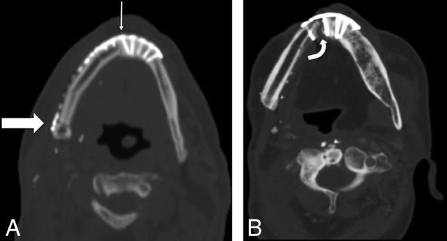
Osseous FF margins. Axial noncontrast CT shows the expected postoperative appearance (A) following right segmental mandibulectomy and fibular FF reconstruction, with a healing symphyseal interface (thin arrow) and a nonunited-but-sharp osteotomy underlying the posterior mandibular body surgical plate (thick arrow). Axial noncontrast CT of a different patient with a fibular FF shows a complicated postoperative appearance (B), with a nonunited, diastatic, irregular symphyseal margin with a periosteal reaction in this patient with osteonecrosis of the fibular FF and native mandible.
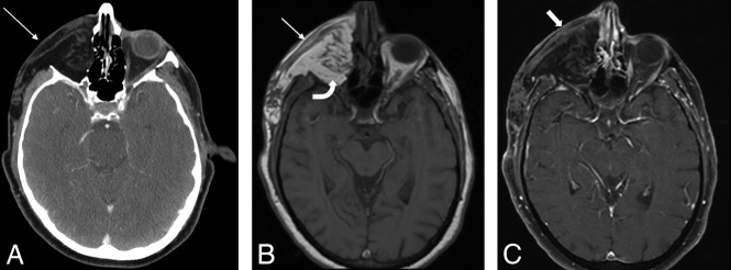
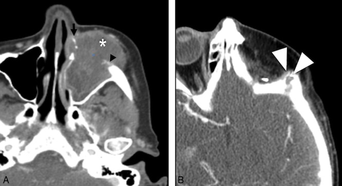
The fatty portion of the flap should be relatively homogeneous without induration, nodularity, or abnormal focal enhancement (Fig 11). The interface of the flap and resection cavity, known as the recipient bed, is the most critical area to examine because this is the site of local disease recurrence. Nodularity, a mass, or focal discrete enhancement is a characteristic imaging appearance of a recurrence (Fig 12). These findings are especially important if the patient has new pain, dysphagia, or any symptom that would suggest recurrent malignancy. Multiple clips are usually present at the vascular pedicle, denoting the anastomosis between the flap and resection cavity, but they are small and rarely degrade image quality.
Fig 11.
Expected FF fat and muscle appearance. The postoperative axial CECT (A) following orbital exenteration and latissimus FF reconstruction shows the normal thin musculature (arrow) and fat of the flap. Axial T1 precontrast MR image (B) shows the FF with muscular striations (arrow). The FF fat (curved arrow) deep to the muscular component is homogeneously hyperintense. Axial postcontrast fat-saturated T1 MR image (C) shows the FF muscular thin, non-nodular enhancement (block arrow), similar to that in other muscles in the H&N.
Fig 12.
Tumor recurrence. Preoperative axial CECT (A) shows a T4a maxillary sinus SCC. Following maxillectomy and orbital exenteration with ALT FF reconstruction, the patient had a biopsy-proved recurrence (white arrowheads) at the margins of the ALT FF on postoperative CECT (B) several months later.
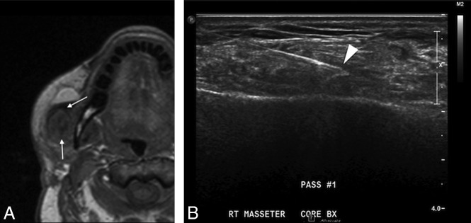
Muscular flap components are usually striated, thin, and relatively flat (Fig 11). On CECT, the flap muscle is isodense to striated muscle elsewhere. The MR signal intensity and enhancement pattern have been described and are predictable, with moderate-to-intense enhancement.13,24–26 In the early posttreatment period, the flap may be edematous, hypointense on T1-weighted images (Fig 13), hyperintense on T2-weighted images, and enhance with gadolinium contrast. Later, the muscular portion of the flap decreases in bulk and becomes heterogeneous on T1- and T2-weighted MR images and relatively more hypoattenuating on CT as the denervated muscle becomes fatty.21,27
Fig 13.
Inflammation. Postoperative T1 axial MR image (A) after reconstruction with a latissimus FF shows hypointense abnormal signal (arrows) and enlargement of the right masseter. Considerations included myositis, denervated muscle, or recurrent intramuscular tumor. Ultrasound-guided biopsy (B) shows good positioning of the needle tip in the muscle (arrowhead). Final pathology results were benign skeletal muscle and fibroadipose tissue, consistent with focal inflammation; no malignant cells were present.
Complications
Radiologists will encounter cross-sectional imaging studies performed to evaluate postoperative complications in patients with FF. Complications have been divided into early or late,28 but in actuality, there is overlap between the 2 categories.
The survival rate of a flap is around 95%, but early complications soon after a reconstructive FF operation include ischemia, infection, bleeding, and dehiscence.29 These are closely monitored clinically at the bedside and rarely require cross-sectional imaging. Ischemia of FFs may be due to either venous or arterial thrombosis.8 The surgical team is on high alert for signs of FF ischemia in the immediate postoperative period. Patients undergo frequent inspection of tissue color, capillary refill, turgor, and temperature.12,30 Various other techniques, including Doppler monitoring and needle pricks, are also used in the immediate postoperative period. When recognized and surgically treated promptly, compromised FFs have a salvage rate of 50%–75%.8 Management includes re-exploration of the site, with possible thrombectomy and anastomosis revision.
More commonly imaged complications occur later in the postoperative period and include infection, fistulas, hardware exposure, and osteonecrosis. Infection and fistulas can present with nonspecific imaging features, such as soft-tissue swelling and stranding, loss of fat planes, and collections of fluid and air. In patients with H&N cancer with a history of radiation therapy or a recent operation, unless baseline postoperative studies are available, it may be impossible to distinguish infection from treatment-related changes solely on the basis of imaging alone. However, some cases may be more obvious, with new rim-enhancing fluid collections or areas of frank dehiscence (Fig 14).
Fig 14.
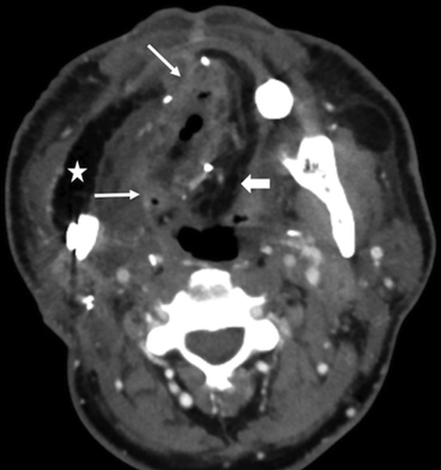
FF Infection. This patient had fever, elevated white blood cell count, and purulent left neck drainage following radial forearm FF and fibular FF reconstruction for T4aN2c SCC of the right oral tongue. Axial CECT shows an abscess with flap induration, irregular enhancement, and pockets of gas in the right floor of mouth (arrows). Note stranding in the fatty flap (block arrow), compared with the homogeneous fat density in the lateral flap that reconstructed the buccal mucosa (star).
Dehiscence of FFs overlying surgical hardware can result in exposure of the surgical construct (Fig 15). Hardware exposure and extrusion are the most commonly cited flap complications and occur in around 15% of patients.29,31 This complication is often seen in association with continued tobacco use.
Fig 15.
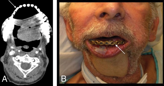
Hardware exposure. A patient with T4aN0M0 left floor of mouth SCC status post pectoralis rotational flap and surgical bar reconstruction. A fibular FF reconstruction was originally planned but abandoned due to severe peripheral vascular disease. The patient was lost to follow-up for 2 years and then presented with a 1-month history of hardware exposure with a large area of exposed mandibular hardware (arrow) on axial CECT (A) and clinical examination (B).
Osteonecrosis is primarily a clinical diagnosis and is seen in patients with exposed bone.32 CT features of cortical destruction, trabecular disorganization, periosteal reaction (Fig 10B), and associated soft-tissue abnormality overlap findings of osteomyelitis and tumor recurrence.33,34 CT is usually performed not to differentiate etiologies but to determine the extent of disease. Osteonecrosis is treated surgically, while osteomyelitis will usually be treated medically. Biopsy is generally avoided in cases of bisphosphonate osteonecrosis because it may cause progression and further damage but can be definitive in differentiating osteoradionecrosis from tumor recurrence.34,35 One useful distinguishing imaging finding is that abnormalities at a site distant or contralateral to the primary tumor are more likely osteoradionecrosis.34
Ossification of the vascular pedicle, while not a surgical complication, is an imaging pitfall. This entity presents in patients with fibular FF as a thin, linear, or curvilinear ossific density following the course of the vascular pedicle (Fig 16), the result of ossification of a strip of periosteum inset with the vascular pedicle. This ossification can be seen in up to 50% of patients as soon as 1 month after the operation and may present clinically as a palpable mass.36
Fig 16.
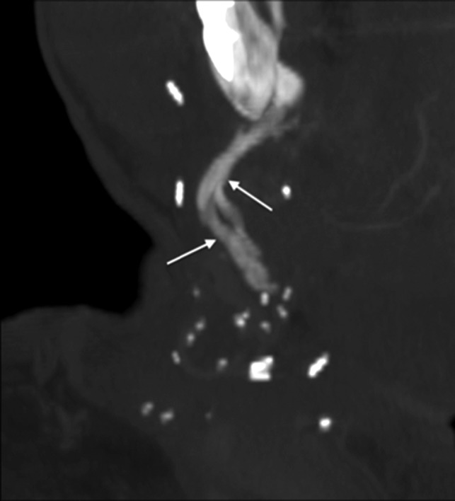
Vascular pedicle ossification. A patient with fibular FF following right mandibulectomy for T2N1 SCC of the mandibular gingiva returned 8 weeks after the operation with a palpable right-neck mass. Oblique coronal MIP reconstruction from CECT, bone windows, shows linear ossification (arrows) along the course of vascular pedicle, corresponding to the palpable abnormality.
Surveillance for tumor recurrence is the main focus of follow-up imaging. Primary site recurrences most often occur at the margins of the resection at the flap–native tissue interface and have nodular or masslike enhancement with signal characteristics similar to those of the original tumor (Fig 12).37–39 Nodal recurrence may have the typical expected regional distribution of the original tumor or may vary from the norm due to surgical alteration of drainage pathways.28 The third recurrence pattern is perineural spread of disease. If one is not actively assessing perineural tumor, the findings may be subtle enough to evade detection.
Conclusions
Postoperative imaging in patients with H&N reconstruction is challenging. An organized approach and thorough understanding of FF appearances and complications will help interpreting radiologists provide accurate, useful imaging reports for both the patients and their referring clinicians.
ABBREVIATIONS:
- ALT
anterolateral thigh
- CECT
contrast-enhanced CT
- FF
free flap
- H&N
head and neck
- SCC
squamous cell carcinoma
Footnotes
Disclosures: Amanda S. Corey—UNRELATED: Consultancy: Rad MC LLC; Payment for Lectures Including Service on Speakers Bureaus: The Osler Institute, Comments: Continuing Medical Education lectures. Patricia A. Hudgins—UNRELATED: Royalties: Elsevier/Amirsys, Comments: medical textbook authorship.
Paper previously presented as an educational electronic exhibit at: Annual Meeting of the American Society of Head and Neck Radiology, September 7–11, 2016; Washington, DC.
References
- 1. Urken ML, Weinberg H, Buchbinder D, et al. Microvascular free flaps in head and neck reconstruction: report of 200 cases and review of complications. Arch Otolaryngol Head Neck Surg 1994;120:633–40 10.1001/archotol.1994.01880300047007 [DOI] [PubMed] [Google Scholar]
- 2. Blackwell KE. Unsurpassed reliability of free flaps for head and neck reconstruction. Arch Otolaryngol Head Neck Surg 1999;125:295–99 10.1001/archotol.125.3.295 [DOI] [PubMed] [Google Scholar]
- 3. Corbitt C, Skoracki RJ, Yu P, et al. Free flap failure in head and neck reconstruction. Head Neck 2014;36:1440–45 10.1002/hed.23471 [DOI] [PubMed] [Google Scholar]
- 4. Su WF, Hsia YJ, Chang YC, et al. Functional comparison after reconstruction with a radial forearm free flap or a pectoralis major flap for cancer of the tongue. Otolaryngol Head Neck Surg 2003;128:412–18 10.1067/mhn.2003.38 [DOI] [PubMed] [Google Scholar]
- 5. Urken ML. Atlas of Regional and Free Flaps for Head and Neck Reconstruction. New York: Raven Press; 1995 [Google Scholar]
- 6. Ferlay J, Soerjomataram I, Dikshit R, et al. Cancer incidence and mortality worldwide: sources, methods and major patterns in GLOBOCAN 2012. Int J Cancer 2015;136:E359–86 10.1002/ijc.29210 [DOI] [PubMed] [Google Scholar]
- 7. Conley J, Patow C, eds. Flaps in Head & Neck Surgery. 2nd ed New York: Thieme; 1989 [Google Scholar]
- 8. Goldenberg D, Goldstein BJ, eds. 7.3 Facial Reconstruction. Stuttgart: Thieme; 2011 [Google Scholar]
- 9. Resto VA, Deschler DG. Complications of skin, cartilage, and bone grafts. In: Eisele DW, Smith RV. Complications in Head and Neck Surgery. 2nd ed Philadelphia: Elsevier Mosby; 2009:803–11 [Google Scholar]
- 10. Weiland AJ, Phillips TW, Randolph MA. Bone grafts: a radiologic, histologic, and biomechanical model comparing autografts, allografts, and free vascularized bone grafts. Plast Reconstr Surg 1984;74:368–79 10.1097/00006534-198409000-00006 [DOI] [PubMed] [Google Scholar]
- 11. Sparks DS, Wagels M, Taylor GI. Bone reconstruction: a history of vascularized bone transfer. Microsurgery 2018;38:7–13 10.1002/micr.30260 [DOI] [PubMed] [Google Scholar]
- 12. Wester DJ, Whiteman ML, Singer S, et al. Imaging of the postoperative neck with emphasis on surgical flaps and their complications. AJR Am J Roentgenol 1995;164:989–93 10.2214/ajr.164.4.7726063 [DOI] [PubMed] [Google Scholar]
- 13. Hudgins PA. Flap reconstruction in the head and neck: expected appearance, complications, and recurrent disease. Semin Ultrasound CT MR 2002;23:492–500 10.1016/S0887-2171(02)90039-9 [DOI] [PubMed] [Google Scholar]
- 14. Cummings CW, Haughey BH, Thomas JR. Cummings Otolaryngology: Head and Neck Surgery. St. Louis: Mosby; 2005 [Google Scholar]
- 15. Chim H, Salgado CJ, Seselgyte R, et al. Principles of head and neck reconstruction: an algorithm to guide flap selection. Semin Plast Surg 2010;24:148–54 10.1055/s-0030-1255332 [DOI] [PMC free article] [PubMed] [Google Scholar]
- 16. Wong CH, Wei FC. Microsurgical free flap in head and neck reconstruction. Head Neck 2010;32:1236–45 10.1002/hed.21284 [DOI] [PubMed] [Google Scholar]
- 17. Syed F, Spector ME, Cornelius R, et al. Head and neck reconstructive surgery: what the radiologist needs to know. Eur Radiol 2016;26:3345–52 10.1007/s00330-015-4184-3 [DOI] [PubMed] [Google Scholar]
- 18. Wei FC, Jain V, Suominen S, et al. Confusion among perforator flaps: what is a true perforator flap? Plast Reconstr Surg 2001;107:874–76 10.1097/00006534-200103000-00037 [DOI] [PubMed] [Google Scholar]
- 19. Howard BE, Nagel TH, Barrs DM, et al. Reconstruction of lateral skull base defects: a comparison of the submental flap to free and regional flaps. Otolaryngology Head Neck Surg 2016;154:1014–18 10.1177/0194599816634296 [DOI] [PubMed] [Google Scholar]
- 20. Netter FH. Atlas of Human Anatomy. Philadelphia: Elsevier; 2010 [Google Scholar]
- 21. Saito N, Nadgir RN, Nakahira M, et al. Posttreatment CT and MR imaging in head and neck cancer: what the radiologist needs to know. RadioGraphics 2012;32:1261–82; discussion 1282–94 10.1148/rg.325115160 [DOI] [PubMed] [Google Scholar]
- 22. Kelly AM, Cronin P, Hussain HK. Preoperative MR angiography in free fibula flap transfer for head and neck cancer: clinical application and influence on surgical decision making. AJR Am J Roentgenol 2007;188:268–74 10.2214/AJR.04.1950 [DOI] [PubMed] [Google Scholar]
- 23. Welkoborsky HJ, Deichmüller C, Bauer L, et al. Reconstruction of large pharyngeal defects with microvascular free flaps and myocutaneous pedicled flaps. Curr Opin Otolaryngol Head Neck Surg 2013;21:318–27 10.1097/MOO.0b013e3283631ea2 [DOI] [PubMed] [Google Scholar]
- 24. Chong J, Chan LL, Langstein HN, et al. MR imaging of the muscular component of myocutaneous flaps in the head and neck. AJNR Am J Neuroradiol 2001;22:170–74 [PMC free article] [PubMed] [Google Scholar]
- 25. Hudgins PA, Burson JG, Gussack GS, et al. CT and MR appearance of recurrent malignant head and neck neoplasms after resection and flap reconstruction. AJNR Am J Neuroradiol 1994;15:1689–94 [PMC free article] [PubMed] [Google Scholar]
- 26. Ginsberg LE. Imaging pitfalls in the postoperative head and neck. Semin Ultrasound CT MR 2002;23:444–59 10.1016/S0887-2171(02)90035-1 [DOI] [PubMed] [Google Scholar]
- 27. Fox MG, Bancroft LW, Peterson JJ, et al. MRI appearance of myocutaneous flaps commonly used in orthopedic reconstructive surgery. AJR Am J Roentgenol 2006;187:800–06 10.2214/AJR.05.0484 [DOI] [PubMed] [Google Scholar]
- 28. Garcia MR, Passos UL, Ezzedine TA, et al. Postsurgical imaging of the oral cavity and oropharynx: what radiologists need to know-erratum. RadioGraphics 2015;35:1624 10.1148/rg.2015154015 [DOI] [PubMed] [Google Scholar]
- 29. Haughey BH, Wilson E, Kluwe L, et al. Free flap reconstruction of the head and neck: analysis of 241 cases. Otolaryngol Head Neck Surg 2001;125:10–17 10.1067/mhn.2001.116788 [DOI] [PubMed] [Google Scholar]
- 30. Kubo T, Yano K, Hosokawa K. Management of Flaps with Compromised Venous Outflow in Head and Neck Microsurgical Reconstruction. Vol 22 Wiley Online LibraryAccessed February 20, 2018; 2002:391–95. https://onlinelibrary.wiley.com/doi/abs/10.1002/micr.10059. Accessed February 20, 2018. [DOI] [PubMed] [Google Scholar]
- 31. Day KE, Desmond R, Magnuson JS, et al. Hardware removal after osseous free flap reconstruction. Otolaryngol Head Neck Surg 2014;150:40–46 10.1177/0194599813512103 [DOI] [PMC free article] [PubMed] [Google Scholar]
- 32. Estilo CL, Van Poznak CH, Wiliams T, et al. Osteonecrosis of the maxilla and mandible in patients with advanced cancer treated with bisphosphonate therapy. Oncologist 2008;13:911–20 10.1634/theoncologist.2008-0091 [DOI] [PubMed] [Google Scholar]
- 33. Morag Y, Morag-Hezroni M, Jamadar DA, et al. Bisphosphonate-related osteonecrosis of the jaw: a pictorial review. RadioGraphics 2009;29:1971–84 10.1148/rg.297095050 [DOI] [PubMed] [Google Scholar]
- 34. Chong J, Hinckley LK, Ginsberg LE. Masticator space abnormalities associated with mandibular osteoradionecrosis: MR and CT findings in five patients. AJNR Am J Neuroradiol 2000;21:175–78 [PMC free article] [PubMed] [Google Scholar]
- 35. Ruggiero SL, Fantasia J, Carlson E. Bisphosphonate-related osteonecrosis of the jaw: background and guidelines for diagnosis, staging and management. Oral Surg Oral Med Oral Pathol Oral Radiol Endod 2006;102:433–41 10.1016/j.tripleo.2006.06.004 [DOI] [PubMed] [Google Scholar]
- 36. Glastonbury CM, van Zante A, Knott PD. Ossification of the vascular pedicle in microsurgical fibular free flap reconstruction of the head and neck. AJNR Am J Neuroradiol 2014;35:1965–69 10.3174/ajnr.A3979 [DOI] [PMC free article] [PubMed] [Google Scholar]
- 37. Lall C, Tirkes TA, Patel AA, et al. Flaps, slings, and other things: CT after reconstructive surgery–expected changes and detection of complications. AJR Am J Roentgenol 2012;198:W521–33 10.2214/AJR.11.7552 [DOI] [PubMed] [Google Scholar]
- 38. Offiah C, Hall E. Post-treatment imaging appearances in head and neck cancer patients. Clin Radiol 2011;66:13–24 10.1016/j.crad.2010.09.004 [DOI] [PubMed] [Google Scholar]
- 39. Tomura N, Watanabe O, Hirano Y, et al. MR imaging of recurrent head and neck tumours following flap reconstructive surgery. Clin Radiol 2002;57:109–13 10.1053/crad.2001.0720 [DOI] [PubMed] [Google Scholar]


