

Abstract
The success of tissue-engineered vascular graft (TEVG) predominantly relies on the selection of a suitable biomaterial and graft design. Natural biopolymer silk has shown great promise for various tissue-engineering applications. This study is the first to investigate Indian endemic non-mulberry silk (Antheraea assama-AA) – which inherits naturally superior mechanical and biological traits (e.g., RGD motifs) compared to Bombyx mori-BM silk, for TEVG applications. We designed bi-layered biomimetic small diameter AA-BM silk TEVGs adopting a new fabrication methodology. The inner layer showed ideally sized (~40 μm) pores with interconnectivity to allow cellular infiltration, and an outer dense electrospun layer that confers mechanical resilience. Biodegradation of silk TEVGs into amino acids as resorbable byproducts corroborates their in vivo remodeling ability. Following our previous reports, we surgically implanted human adipose tissue-derived stromal vascular fraction (SVF) seeded silk TEVGs in Lewis rats as abdominal aortic interposition grafts for 8 weeks. Adequate suture retention strength (0.45 ± 0.1 N) without any blood seepage post-implantation substantiate the grafts’ viability. AA silk-based TEVGs showed superior animal survival and graft patency compared to BM silk TEVGs. Histological analysis revealed neo-tissue formation, host cell infiltration and graft remodeling in terms of extracellular matrix turnover. Altogether, this study demonstrates promising aspects of AA silk TEVGs for vascular tissue engineering applications.
Keywords: non-mulberry silk, vascular grafts, tissue engineering, biodegradation, tissue remodeling
Graphical Abstract

1. INTRODUCTION
Cardiovascular disease (CVD) remains the primary cause of death globally and coronary artery disease (CAD) is the most prominent form of CVD [1]. The main cause of CVD is occlusion of blood vessels, which restricts blood supply to vital organs. Current treatment options rely on surgical revascularization by either stent placement or implantation of an interposition graft to bypass the occlusion. In the case of coronary artery bypass surgery, surgeons commonly use the saphenous vein; however, removal of the vein causes significant donor site morbidity. Moreover, limited availability of autologous grafts restrict their application [2]. Therefore, an urgent need exists to identify a viable option for bypass of occluded small diameter vessels. Tissue engineered vascular grafts (TEVGs) have recently made remarkable progress. The fundamental difference between conventional vascular grafts and current approaches to graft development is the biodegradability of the polymer. In 1980s, Weinberg and Bell fabricated a collagen gel based tubular graft for vascular tissue engineering [3]. Since then, a number of biodegradable natural/synthetic polymers have been investigated as „off the shelf’ vascular grafts. Poly (lactic acid) [PLA] and poly (glycolic acid) [PGA], along with their various co-polymers, are a popular choice for vascular tissue engineering applications owing to their tunable mechanical and degradation properties [4]. Despite several advantages, these synthetic polymers have a number of drawbacks including their moderate biocompatibility and acidic degradation products [5].
Among several natural polymers used for tissue engineering applications, the structural protein silk has shown great potential. The advantages of using silk for vascular tissue engineering include its appropriate mechanical properties, tunable degradation producing non-toxic by-products and good biocompatibility [6–9]. Lovett and colleagues first reported the fabrication of silk fibroin microtubes using dip coating method [10] followed by a gel spinning process to fabricate silk-based tubular grafts. In this study, the dip coating was not automated and therefore did not provide uniform wall thickness. However, the gel spun tubes demonstrated good patency and host cell infiltration at 4 weeks in vivo [11, 12]. Recent studies suggest that there are several scaffold design parameters – such as porosity, pore size and other properties – which determine the performance of TEVGs [13]. Hence, it becomes crucial that the graft design should be flexible in terms of these parameters. The major limitation with gel spun tubes is that they are minimally flexible with alteration of pore size owing to use of very high percentage of silk protein (~25–35%), leading to smaller pore size [11]. Braided silk fiber-based tubes have also shown promising results but exhibit prohibitively slow degradation and remodeling in vivo [14]. Furthermore, they posed several other complications including sub-optimal anastomotic strength and tube permeability leading to blood leakage [15, 16]. Electrospun silk grafts are mechanically suitable but they are limited due to small pore size, which prohibits host cell infiltration and graft remodeling [17]. A recent study has demonstrated rapid endothelialization of electrospun silk vascular grafts in a rat model [18]. In our group, we have constructed silk vascular grafts based on layering patterned silk films with vascular cells. Although this method produced cell and fiber alignment that mimics the native vessel architecture, the mechanics (e.g. suture retention) were inadequate to evaluate these grafts in vivo [19]. Prior literature clearly validates the use of silk fibroin as a natural biomaterial for vascular tissue engineering applications and suggests that further advancement is required in terms of flexibility with graft design parameters.
Despite being the common method for fabricating porous silk scaffolds, direct implementation of the freeze-drying (lyophilization) process alone has not been reported previously for preparing silk-based TEVGs. This is possibly due to the limitation of the lyophilization technique, which is suitable for nearly 1 cm working depth, posing scaffold length constraints. In the present study, we were able to overcome this limitation by using a specific 3D printed mold (Figure S1) and following a new facile fabrication methodology (Figure 1). We adopt a molding approach followed by conventional lyophilization to obtain the porous tubular core, which is further coated with an outer electrospun layer to yield mechanically resilient, bilayered silk fibroin conduits. Our approach provides several additional features over previously reported techniques including precise control over porosity, uniform wall thickness and reproducibility. Bi-layered silk grafts fabricated in the present study are morphologically biomimetic having inner porous layer similar to tunica media and outer fibrous electrospun layer mimicking adventitia. It may also provide flexibility with various graft design parameters (e.g. tunable degradation and mechanical properties). Moreover, all prior studies report the use of mulberry Bombyx mori (BM) silk in various formats; but non-mulberry Indian endemic Antheraea assama (AA) silk is unexplored in the field of vascular tissue engineering. Our previous in vitro studies using 2D films suggest that AA silk supports vascular cell growth and functionality; moreover, it has superior mechanical/elastic properties owing to its unique molecular architecture (polyalanine repeats without any intervening amino acid) [19, 20]. Another unique advantage of AA silk is the natural presence of RGD (Arginine-Glycine-Aspartic acid) peptides, which have been shown to reduce acute thrombosis in vivo [21]. In the present study, we adopted a new facile methodology to fabricate silk TEVGs and attempted to explore the use of AA silk in combination and compared with BM silk in vitro and in vivo in a rat aortic interposition graft model over eight weeks.
Figure 1:

Schematic representation of fabrication methodology of bi-layered small diameter silk scaffolds. The inner porous layer is prepared by molding and lyophilization based approach followed by coating with an outer nanofibrous electrospun layer.
2. MATERIALS AND METHODS
2.1. Isolation of Silk Protein
Silk fibroin (SF) protein was obtained from two different sources: mulberry Bombyx mori (BM) silk cocoons and non-mulberry Antheraea assama (AA) silk glands following previously described protocols [19, 22]. Silk worms and cocoons were procured from a local farmhouse. BM cocoons were chopped into small pieces, degummed in 0.02 M Na2CO3, dissolved in 9.3 M LiBr (#213225, Sigma-Aldrich) and dialyzed against distilled water to obtain regenerated SF protein. In contrast with BM silk, the aqueous AA silk was obtained directly from silk glands because AA silk fibers are insoluble in LiBr [23]. AA SF was obtained from silk glands and dissolved in 1% sodium dodecyl sulfate (SDS, #L3771, Sigma-Aldrich) followed by dialysis at 4 °C against MilliQ water. SF protein solutions were stored at 4 °C until use.
2.2. Scaffold Fabrication
We fabricated two variants of bi-layered silk scaffolds consisting of an inner lyophilized porous layer and outer electrospun layer. For the first scaffold type, we used only BM protein (6% w/v) to fabricate the inner lyophilized porous layer. The higher concentration (>3–4%) of AA silk forms hydrogel at physiological temperature. Hence, for the second scaffold type, we used a combination of BM and AA proteins (1:1 ratio of 10% BM protein and 2% AA protein (w/v) keeping 6% final protein concentration). In a previous report, we have shown that the aqueous solutions of BM and AA silk forms homogenous solution, which could be used for fabrication of blend scaffolds [24]. Tubular scaffolds were fabricated using custom-made 3D printed molds as illustrated in Figure 1 and Figure S1. Our mold consisted of 3D printed base/cap, a polypropylene tube (3 cm long), stainless steel rod (1.1 mm diameter, 4 cm long) and a stainless steel cylinder (2 mm internal diameter, 3 cm long). Silk fibroin (SF) solution was injected into the void space between the central rod and polypropylene tube using a syringe followed by freezing in a −20 °C freezer for 2 h. The central rod and cap were removed rapidly (avoiding any possible melting of SF) to expose the lumen of the frozen SF solution. The mold was kept at −20 °C overnight and lyophilized for 24 h. The lyophilized porous SF tubular scaffolds were pushed out from the mold and soaked in 80% (v/v) ethanol to induce water stability.
The outer electrospun layer was coated onto the wet (ethanol soaked) lyophilized inner layer. The electrospinning solution consisted of 1:1 (v/v) ratio of 10% w/v polycaprolactone (#440744, average Mn 80,000, Sigma-Aldrich) and 10% w/v BM silk in 1,1,1,3,3,3-Hexafluoro-2-propanol (#105228, HFP, Sigma Aldrich). The ethanol soaked tubular scaffolds were mounted on a stainless steel mandrel (diameter 0.8 mm). The outer electrospun layer was fabricated using a custom-made electrospinning set-up described previously [25]. The following parameters were used for electrospinning: flow rate (100 μL/min), tip to collector distance (10 cm), applied voltage difference (15 kV), rotational speed (200 rpm), translational speed (50 mm/sec), temperature (~25 °C) and humidity (~47%). Two scaffolds were coated per cycle with 300 μL electrospinning solution. Bi-layered scaffolds were stored in 80% ethanol until use at 4 °C. Scaffold variants are designated as follow: 1) BM: inner porous layer made up of BM protein, without electrospun layer; 2) BMES: BM scaffold with outer electrospun layer; 3) BA: inner porous layer made up of 1:1 v/v ratio of 10% (w/v) BM protein and 2% (w/v) AA protein, without electrospun layer; 4) BAES: BA scaffold with outer electrospun layer.
2.3. Scanning Electron Microscopy (SEM) and micro-CT Analysis
Vertical and horizontal sections of bi-layered silk scaffolds (exposing lumen and cross-section) were sputter coated (Sputter Coater 108 auto, Cressington Scientific Instruments, Cranberry Township, PA) and imaged under scanning electron microscope (SEM, JEOL JSM-6510LV/LGS). Scaffold dimensions (inner and outer diameter, thickness of porous and electrospun layer) were measured using ImageJ (National Institute of Health, USA). A total of 10–15 measurements were recorded for n=3 samples of each scaffold variant. Silk scaffolds were further subjected to microCT imaging on a Scanco microCT 50 (Scanco Medical, Bassersdorf, Switzerland) scanner at a nominal resolution of 1.2 μm and a beam energy of 45Kvp (high contrast conditions). The scaffolds were scanned individually without a liquid medium. 3D volumes were reconstructed from the raw data using the Scanco software, which also performs an automatic calibration of the images for mineral density using built-in algorithms for the particular scanning conditions. The Scanco 3D Bone Morphometry software was used to define the scaffold region and subsequently process the 3D volume. A 0.3 g/cc global threshold was used for segmentation of the strut material from the background. The geometric properties reported are pore volume fraction inside the scaffold, means and distribution of pore size. Each of these properties were calculated individually for inner freeze dried porous and outer electrospun nanofibrous layers.
2.4. Analysis of Mechanical Properties
2.4.1. Uniaxial (Longitudinal and Circumferential) Tensile Testing
All of the mechanical data for silk scaffolds was obtained using phosphate buffered saline (PBS) soaked wet scaffolds. Uniaxial tensile tests were performed using a tensile testing device with pneumatic grips (Instron, model 5543A). For longitudinal tensile testing, 3 cm long scaffolds (n=6) were cut open through the lumen to form a strip and both ends were clamped between pneumatic grips leaving ~2 cm gauge length. While clamping, precautions were taken to keep both of the scaffold ends flat in order to ensure uniform load distribution throughout the scaffold wall. Specimen length and width were recorded using a digital caliper (Thermo Fisher Scientific, Waltham, MA); whereas effective thickness of specimens was calculated by processing SEM images using ImageJ software. Load-displacement curves were obtained at room temperature with a crosshead speed of 2 mm min−1 until failure. For circumferential tensile testing (ring test), scaffold rings (n=12 each) were cut (2 mm length) and a previously described protocol was followed with minor modifications [26]. Elastic modulus of bi-layered silk scaffolds in both directions was calculated as the slope of the stress-strain curves in the low and high stress regions and is represented as low and high modulus respectively as described previously [27]. The transition point between low and high stress regions was defined as the point having maximum normal distance from the global secant. Maximum stress and strain values were also recorded at the failure point.
2.4.2. Suture Retention Strength
Suture retention strength of silk scaffolds was determined following American National Standard Institute–Association for the Advancement of Medical Instruments (ANSI/AAMI) VP20 standards [28]. Scaffolds were cut open longitudinally to obtain rectangular strips (n=6, length 20 mm). A single 7–0 polypropylene (SURGIPRO™ II, Syneture) suture was used to create a single loop ~2 mm away from the end. The free ends of the suture were first secured using laboratory labeling tape (Fisher Scientific) keeping scaffold at the center of the loop and the tape was further clamped in the upper pneumatic grip of tensile testing device (Instron model 5543A). Another end of the scaffold strip was secured in the lower grip and any slack was removed prior to recording the data. Load-displacement curves were obtained at a crosshead speed of 2 mm min−1 until failure. The maximum load prior to scaffold tear-off is reported as suture retention strength. Suture retention tension was calculated by dividing the suture retention force by scaffold thickness as previously reported [28].
2.4.3. Dynamic Compliance
A custom-made vascular perfusion system was used to analyze dynamic compliance of the silk scaffolds as described previously [28]. In brief, the perfusion system consisted of a flow loop and a centrifugal pump (Biomedicus) that provides pulsatile flow and induces physiologically relevant intraluminal pressure (120/80 mmHg). A representative image of a silk scaffold mounted in the testing chamber for pulsatile flow mediated testing is shown in Figure S3–A. A He–Ne laser micrometer (Beta LaserMike, Dayton, OH) was used for real time measurement of the scaffold’s outer diameter under the influence of pulsatile flow. The silk scaffolds (n=6) were mounted in a testing chamber and both ends were secured to stainless steel mounts using a 3–0 silk suture. The flow loop and testing chamber were filled with DI water. The interluminal fluid was maintained at 37 °C. A pulsatile flow was induced in the flow loop using the centrifugal pump and a physiological intraluminal pressure of 120 mmHg over 80 mmHg was maintained with minimal or no leakage from scaffold wall. Pressure and outer diameter of the scaffolds were recorded for 7 hours. For calculating the dynamic compliance, measurements of scaffold inner diameter (ID) were derived by assuming incompressibility of the scaffold wall under dynamic flow conditions as follows:
IDP = Scaffold inner diameter at physiological pressure; ODP = Scaffold outer diameter at physiological pressure recorded using laser micrometer; A = Cross-sectional area of the scaffold wall calculated by processing the SEM images using ImageJ software.
The inner diameter values were used to calculate the dynamic compliance of the silk scaffolds using the following expression:
Where ID120 = Scaffold inner diameter at 120 mmHg intraluminal pressure; ID80 = Scaffold inner diameter at 80 mmHg intraluminal pressure; P120 = 120 mmHg; P80 = 80 mmHg
Scaffold dilation under dynamic pulsatile flow was also calculated in order to assess any possible plastic deformation with time. The recorded average outer diameter of the scaffold at the end of 7 hours of pulsatile flow was divided by initial diameter to calculate creep. Furthermore, β-stiffness at the initial and final time point was calculated using the following expression:
2.4.4. Burst Strength
The burst strength of silk scaffolds (n=6) was measured by recording the maximum pressure sustained without failure (bursting). A custom-made set-up was used as described previously [28]. Briefly, both ends of the scaffolds were secured on stainless steel tubes (fixed in the flow loop test chamber) using 3–0 silk sutures. One of the stainless steel tubes was connected to a syringe pump (Harvard Apparatus, Holliston, MA) and a digital manometer (pressure range 0–60 psi, Weiss), while the other tube was blocked making it a closed loop. The working chamber was filled with saline to submerge the specimen and scaffolds were infused with saline at a rate of 100 mL min−1 until failure. Maximum pressure before scaffold failure was recorded and considered as burst pressure.
2.5. In Vitro Degradation Analysis of Scaffolds
BMES and BAES tubular scaffolds (n=4, length: 1.5 cm) were further assessed for in vitro enzymatic degradation in the presence of protease XIV (#P5147, Sigma-Aldrich) following a previously described methodology [19]. Dry weight of the scaffolds was recorded initially and each scaffold was submerged in 1 mL of enzyme solution (2U mL−1 in PBS). In another set, scaffolds were submerged in PBS without the enzyme (negative control). Scaffolds were maintained at 37 °C and enzyme solution was replaced every 72 h to ensure proper enzyme activity throughout the experiment. In a similar parallel experimental set-up, smaller silk scaffold sections (~2 mm length) were kept in PBS and protease, which were subsequently subjected to SEM imaging. At pre-defined time points, the scaffolds were washed with de-ionized (DI) water, frozen at −20 °C overnight and lyophilized. The dry weight of the scaffolds at each time point was recorded followed by continuation of enzymatic treatment. Scaffold weight was recorded for 28 days (excluding freezing and lyophiliztion time) and percentage of mass remaining was calculated as:
Mt = Scaffold dry weight at time t, M0 = Initial dry weight of scaffold
2.6. Scaffold Seeding with SVF Cells and Dynamic Culture
SVF cells were isolated from nondiabetic female human patients, under the age of 40 years and undergoing liposuction following previously described protocols [29, 30]. Tubular bi-layered silk scaffolds were seeded with SVF cells using a custom-made rotational vacuum seeding device as described previously [28, 29, 31]. The intraluminal pressure was measured in real time and scaffolds showing high pressure (>25 mmHg) were not used for animal implantation. The seeded constructs were transferred to a 500 mL spinner flask (Kontes #Cytostir 882911–0250) containing 100 mL culture media and subjected to dynamic culture at 80 rpm for 48 hours. These scaffolds were further used for rat aortic implantation (see “In vivo implantation in rat and angiogram recording”).
Viability and metabolic activity of SVF cells cultured on silk scaffolds was quantified in a time dependent manner for 15 days using AlamarBlue assay (#DAL1100, Thermo Fisher Scientific, U.S.A.) [19, 22]. Porous lyophilized silk scaffold discs (6 mm diameter, 2 mm thickness) were seeded with SVF cells (~105 cells) and analyzed for cell viability over time. At each time point, media was replaced and AlamarBlue dye was added at 1:10 (dye: media, v/v) ratio followed by 3 hour incubation. The resulting media was read at 570 nm and 600 nm and % Alamar reduction was calculated using an online colorimetric calculator. Data is reported as normalized values compared to Day 1.
2.7. In vivo Implantation in Rat and Angiogram Recording
We used 23 adult Lewis rats (average weight ~200 g) and divided them in 4 groups. First and second groups (n=3 each) were negative control and received acellular BMES and BAES scaffolds respectively. The third group (n=9) received SVF seeded BMES scaffolds (BMES + SVF), and the fourth group (n=8) received SVF seeded BAES scaffolds (BAES + SVF). Two of the rats from the second group and 1 from the fourth group) were euthanized prior to completion of experimental period due to surgical error and excluded from the study. Other animals were sacrificed either after 1 week or after 8 weeks to retrieve the implanted silk graft. All animal surgical procedures were performed in accordance with a protocol approved by University of Pittsburgh Institutional Animal Care and Use Committee (IACUC). Ethylene oxide sterilization may negatively affect the cell proliferation [32]; therefore, silk scaffolds were sterilized using 70% ethanol followed by washing with PBS and overnight conditioning with culture media. SVF seeded silk scaffolds (1 cm long) obtained after 48 h dynamic culture were surgically implanted as abdominal aortic interposition grafts in male Lewis rats following previously described protocols [29, 30, 33]. Animals were sacrificed after either 1 week or 8 weeks. In vivo graft patency was analyzed by recording angiograms soon after animal sacrifice.
2.8. Histological Analysis of Explanted TEVGs
Explanted tissue engineered vascular grafts (TEVGs) were fixed in 4% paraformaldehyde and subjected to histological analysis to observe cell and ECM distribution. Samples were cut into proximal, middle, and distal tissue blocks determined upon explant. Sections from the middle portion were used for all IHC (Immunohistochemistry) and IFC (Immunofluorescence) analysis. Five micron TEVG sections were mounted on slides and processed for immunostaining using previously described protocols [29, 30]. Briefly, tissue sections were permeabilized using 0.1% Triton X-100 followed by blocking in 1% Fetal Bovine Serum (FBS). Primary antibodies used for this study include mouse anti-smooth muscle α-actin (α-SMA, 1:500 dilution, #ab7817, Abcam), rabbit anti-calponin (1:500, #ab46794, Abcam), fluorescein isothiocyanate (FITC) conjugated mouse anti-von Willebrand factor (vWF, 1:250, #V2700–07, US Biological, Salem, Mass) and mouse anti-cluster of differentiation 68 (CD68, 1:250, #ab955, Abcam). The corresponding secondary antibodies used were FITC-conjugated goat anti-rabbit IgG (1:1000, #611–1202, Rockland Inc) and Cy5 conjugated goat anti-mouse IgG (1:1000, ab6563, Abcam). Cell nuclei were counterstained using DAPI (#B2883, Sigma-Aldrich, U.S.A.). Each section was imaged for DAPI (blue) and cell specific markers (green) which were overlaid for clear visualization of positive staining.
TEVG explants and native rat aorta were also investigated for cell, collagen and elastin distribution using H&E, Picro-Sirrus-Red and Verhoeff van Gieson staining respectively. Staining was performed at Histology Core at the McGowan Institute for Regenerative Medicine using 5 μm TEVG sections. Stained sections were imaged using a Nikon 90i fully automated upright microscope.
2.9. Collagen and Elastin Quantification
The collagen and elastin contents of explanted patent silk scaffolds at both 1 and 8 weeks was determined using a hydroxyproline assay and ninhydrin assay respectively. Due to the limited patency of some groups, a maximum of 2 explanted grafts per group was analyzed, with n=3 tissue samples per graft. The hydroxyproline assay indirectly measured the collagen content of each sample using acid hydrolysis followed by treatment with chloramine-T and p-dimethylaminobenzaldehyde (p-DMBA) solutions [34]. The same tissue sample was used to measure elastin, collagen and total protein using a previously published protocol [35]. Both collagen and elastin quantities are reported after normalizing to the total protein content of each tissue segment. A segment of native rat aorta was also processed as a positive control.
2.10. Image Processing
Fiji-ImageJ (National Institute of Health, USA) software was used to process the IFC images. For calculating the total number of cells infiltrated in the scaffold at different time points, 15 randomly selected DAPI stained images (10X) obtained from different sections of the scaffolds (n=3) were processed. The number of nuclei was calculated using the preset ‘Analyze particles’ plugin (ImageJ) which applied a threshold to the circularity range and average area parameters of the cell nuclei (eliminating silk scaffold auto fluorescence and background noise). Furthermore, in order to estimate the presence of CD68 positive cells (representing macrophages) at 1 and 8 week time points, we calculated the percentage of fluorescent area in the scaffold wall stained positive for anti CD68 antibody. A total of six fluorescence images per scaffold variant with randomly selected regions of interest were implemented for this analysis. Silk scaffold auto fluorescence was eliminated using the aforementioned thresholding plugin.
The lumen diameter and wall thickness of the silk scaffolds before and after implantation was also calculated. Scaffold images obtained from SEM prior to cell seeding were used to calculate the lumen diameter and wall thickness before implantation. Moreover, H&E stained images were processed for 1 week and 8 week explants. A minimum of six images per scaffold (n=3) were processed manually by a blinded investigator and results are represented as average value with standard deviation.
2.11. Statistical analysis
All experiments were performed for at least n=3 samples unless otherwise noted. All data is reported as mean ± standard deviation (SD). One-way analysis of variance (ANOVA) was performed following post hoc Tukey’s test using Origin 8.0 software. P values are reported for all the experiments. Two groups with at least P<0.05 were considered significantly different.
3. RESULTS
3.1. Morphometric Analysis
SEM micrographs of scaffold cross sections validated the presence of two distinct layers: inner porous lyophilized layer and outer electrospun layer. Scaffolds had an inner porous layer thickness of 598 ± 53 μm and outer electrospun layer thickness of 119 ± 24 μm, totaling 718 ± 65 μm thickness for the bi-layered scaffold wall. The inner diameter of scaffolds was 918 ± 82 μm. The outer electrospun nanofibrous layer was firmly adhered to the core layer without any visible delamination. The SEM micrographs also demonstrated open interconnected pores at the scaffold cross-section and throughout the lumen (Figure 2A). MicroCT data suggested heterogeneous pore size distribution for inner porous layer of BMES and BAES scaffolds ranging 53 ± 30 μm and 43 ± 24 μm respectively. The pore size of outer nanofibrous electrospun layer was 5±2 μm (Figure S2). Overall porosity of inner layer was 91.63 ± 1.25 % and 87.83 ± 2.14 % respectively for BMES and BAES scaffolds (Figure 2B, C) (P<0.05). The porosity of outer electrospun layer was 41.5 ± 4.94 for both scaffold types, which was significantly lower than inner layer (P<0.01). The three-dimensional view of both silk scaffolds is represented in Video S1.
Figure 2. Morphometric analysis of bi-layered silk scaffolds.

(A) Representative images of tubular silk scaffolds and SEM micrographs showing internal porous architecture (CS: cross-section and lumen). MicroCT analysis of tubular silk scaffolds representing (B) 3D scaffold models and (C) Distribution of pore size of inner porous layer.
3.2. Mechanical Properties
Stress-strain curves showed that the addition of an electrospun layer (BMES and BAES) alters the mechanical response curves of the scaffolds (Figure 3A–D). For longitudinal testing, higher stress at failure was noted for scaffolds with an electrospun layer (BMES and BAES, 0.34 ± 0.70 MPa and 0.36 ± 0.08 MPa respectively) as compared with BM and BA scaffolds (0.12 ± 0.02 MPa and 0.10 ± 0.01 MPa respectively) (P<0.01). However, BMES/BAES (P = 0.987) and BM/BA groups (P = 0.986) were comparable. BA scaffolds showed higher strain at failure than BM/BMES (P<0.01) (Figure S3). The addition of an electrospun layer increased the scaffold modulus in the low stress region and BAES showed a significantly higher values than BMES scaffold (P=0.004). No significant difference was observed in high modulus across any group (P>0.01) (Figure 3A–D). A similar trend was observed for circumferential tensile testing of scaffolds and the addition of the electrospun layer improved the stress at failure (P<0.01). In addition, no significant difference among the groups was observed for strain at failure (p>0.01) (Figure S2–D). In contrast with the longitudinal testing, no significant difference was noted for scaffold modulus in the low stress regions among the groups (p>0.01); however, addition of the electrospun layer increased the scaffolds’ modulus in the high stress region. BMES scaffolds showed the maximum high modulus (0.31 ± 0.04 MPa) and was significantly increased compared to BAES (0.21 ± 0.04, P = 0.0023), BM (0.05 ± 0.01 MPa, P<0.01) and BA (0.08 ± 0.02, P<0.01) scaffolds (Figure 3C–F).
Figure 3. Uniaxial tensile testing of silk scaffolds.
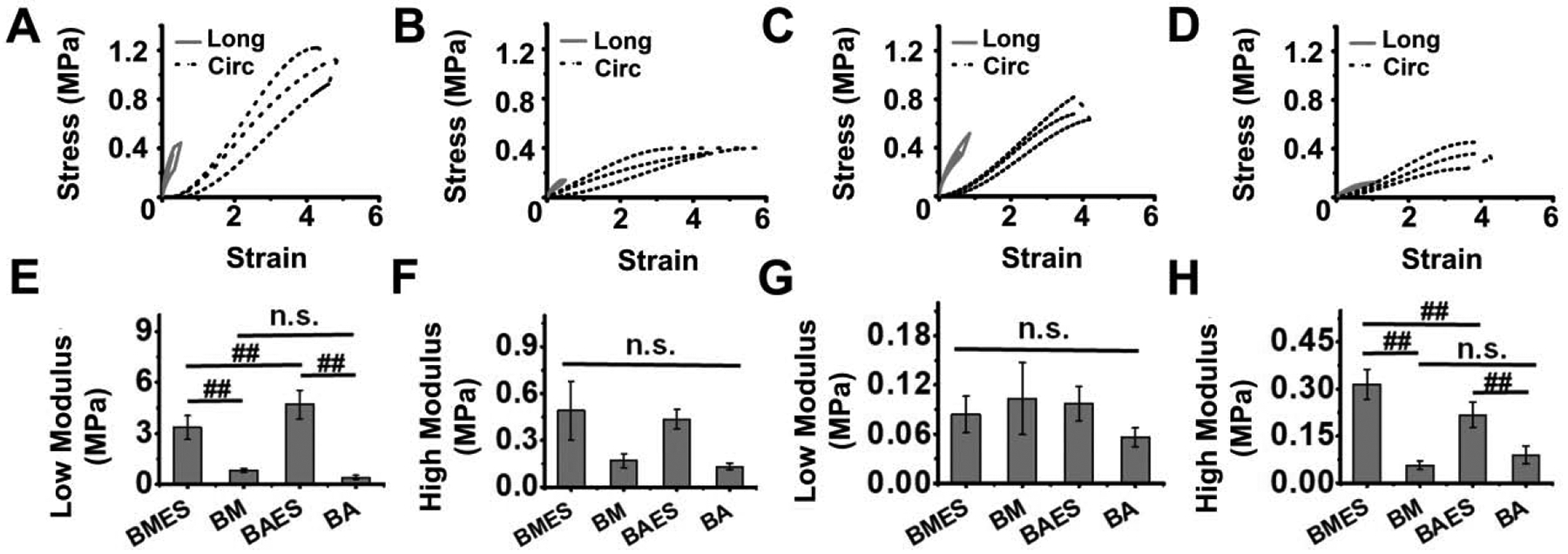
Average stress-strain curves in longitudinal (Long) and circumferential (Circ) directions for (A) BMES, (B) BM, (C) BAES and (D) BA silk scaffolds. Comparison of scaffold average modulus in the low (E, G) and high (F, H) stretch regions in longitudinal (E, F) and circumferential (G, H) directions. (##P<0.01, n.s. = not significant)
Suture retention force for tubular silk scaffolds was 0.38 ± 0.11 N for BMES and 0.46 ± 0.11 N for BAES scaffolds (P = 0.290) (Figure 4A). Similarly, suture retention tension was not significantly different between BMES (520 ± 160 N/m) and BAES scaffolds (620 ± 150 N/m) (P = 0.290, Figure 4B). No significant difference was observed for β stiffness at initial (150 ± 81 vs 205 ± 8) and final (207 ± 80 vs 214 ± 6) time points for BMES vs BAES scaffolds (p>0.01, Figure 4C). Dynamic compliance values were also non-significant at initial and final time points between the two silk scaffold variants (P>0.01, Figure 4D). Creep analysis for silk scaffolds over 7 hours suggests very low creep for both silk scaffolds (1.001 ± 0.005 vs 1.017 ± 0.017 for BMES and BAES) (P>0.01, Figure 4E). Moreover, burst pressure of silk scaffolds was comparable (827 ± 68 mmHg vs 798 ± 100 mmHg) for BMES vs BAES scaffolds (P = 0.650, Figure 4F). In order to demonstrate the pressure-diameter relationship for silk scaffolds, we recorded scaffold diameter at physiologically relevant pulsatile pressure values at T=1h, showing consistency and insignificant distension of the scaffold wall. For both silk scaffold types, pulsatile behavior of pressure and scaffold diameter at 1 hour is shown in Figure S4.
Figure 4: Mechanical properties of bi-layered silk scaffolds.

(A) Comparison of suture retention force and (B) Suture retention tension between the two silk scaffold variants. (C) Comparison of β stiffness and (D) Dynamic compliance of silk scaffolds at initial (T=0h) and final (T=7h) time points under the influence of physiologically relevant pulsatile flow. (E) Creep analysis of silk scaffolds after 7h physiologically relevant pulsatile flow. (F) Comparison of burst pressure of silk scaffolds. (n.s. = not significant)
3.3. In vitro Degradation Profile
We performed both quantitative (by recording the mass loss with time) and qualitative analysis (by comparing the SEM images at different time points) to track the scaffold degradation. The effect of protease on the silk scaffolds is depicted in Figure 5A, representing the scaffold degradation pattern. Scaffolds kept in PBS alone, were smooth and did not show any visual structural alteration; whereas protease treated scaffolds were observed to be degrading with time. Images taken at higher magnification showed the formation of undefined pores in the scaffold struts after exposure to protease activity. All of the scaffolds maintained lumen diameter with no observed visual change with the exception of the BAES scaffolds treated with protease enzymes. Lumen diameter was quantified by analyzing the SEM images using ImageJ software. No significant change was observed for BMES/PBS, BMES/PRT and BAES/PBS groups (P>0.01), however the BAES/PRT group showed a significant decrease (~20% on day 8 and ~40% on day 15 when compared with day 0) in lumen diameter with time (P<0.01, Figure 5B). Both scaffold types lost nearly 50% of their original weight within 15 days and nearly 70% at the end of 30 days in the presence of enzyme (Figure 5C). A significant difference was reported for protease treated and un-treated scaffold groups post 8 days onwards (P<0.01).
Figure 5: In vitro degradation of tubular bi-layered silk scaffolds in the presence of protease XIV.

(A) SEM micrographs showing the scaffold morphology and effect of protease treatment over time. The higher magnification images on the right represent the scaffold degradation pattern (pore formation in scaffold struts) after 15 days of treatment. (B) Quantification of scaffold diameter after 15 days. (C) Graph representing the degradation of silk scaffold (in terms of percentage mass loss) over time in the presence or absence of protease enzyme. (‘/PRT’ represents the presence of protease and ‘/PBS’ represents the absence of protease) (##P<0.01, n.s. = not significant)
3.4. Scaffold Seeding and Proliferation of SVF Cells
The luminal pressure at the proximal end of the scaffold during the cell seeding remained between −10 mmHg and 10 mmHg (Figure 6A). DAPI stained and ImageJ processed images showed uniform distribution of SVF cells along the scaffold wall (Figure 6B). Moreover, >90% cell seeding efficiency was achieved each time, as determined by calculating cell density in the perfused media. Silk scaffolds supported SVF cell viability and proliferation with time and results are reported as normalized values with respect to day 1. As shown in Figure 6C, both scaffolds supported SVF proliferation throughout the experimental time and no significant difference was recorded between the two groups after 15 days (P>0.01). Cells began proliferation after seeding into the silk scaffolds from day 1 onwards and a significant increase was observed at each successive time point with approximately 1.7 fold increase in cell population on day 15 (P<0.01).
Figure 6: Seeding tubular silk scaffolds with SVF cells and viability analysis.

(A) Silk scaffolds were mounted into the rotational vacuum cell seeding device prior to cellular infusion. The graph on the right represents the recorded luminal pressure at the proximal end with time during infusion of cells. (B) SVF seeded scaffolds were exposed to 48 h dynamic culture in a spinner flask and scaffold cross-sections were stained with DAPI (blue) indicating cell nuclei. ImageJ was used to map the cell distribution along the scaffold wall (representative images on the right side of the panel, dashed black line represents the scaffold wall); Scale bar: 200 μm. (C) Graph representing viability and proliferation of SVF cells cultured on silk scaffolds over 15 days under in vitro conditions. (## P<0.01)
3.5. In vivo Implantation and Graft Patency
Silk grafts were suturable and able to withstand the blood flow pressure (120 mmHg) and hemodynamic arterial microenvironment in vivo. Moreover, the electrospun silk/PCL layer prevented blood leakage. However, graft reddening was observed due to the infusion of blood cells in the inner porous layer of the silk scaffold instantly after micro clamp removal. A representative image of a silk graft after anastomosis and clamp removal is shown in Figure 7A. SVF seeded silk grafts were explanted at 1 week and 8 week time points. A gross morphological evaluation of silk explants suggested that 1 week explants demonstrated comparatively higher immune response as evidenced by accumulation of fibrin capsule surrounding the graft; whereas, 8 week explants showed better graft acceptance and dissolution of most of the fibrin capsule. A gross observation of the middle sections of the explanted scaffolds showed the presence of neotissue formation in the lumen of the 8-week explants (Figure 7B and 7C). Out of 21 implants, 3 BMES and 2 BAES grafts were implanted as control (without seeding SVF cells). All rats that received control grafts were observed for 8 weeks; unless impaired mobility of the hind limbs was observed requiring immediate euthanization. Graft performance was categorized into 4 groups and represented as: graft viability, patency, occlusion and acute thrombosis. Representative graph is shown in Figure 7D for SVF seeded silk scaffolds and Figure S5 for control explants. Graft patency was validated by recording angiograms (Figure 7E). Implanted silk scaffolds were determined to be ‘viable grafts’ in cases where no hind limb movement impairment was observed and the rat was bright, alert and responsive (BAR) until the completion of the experimental time. Graft patency was directly derived from angiogram data. Representations of angiograms showing patency of silk grafts after 8 weeks are shown in Video S2. ‘Graft occlusion’ include all the occluded grafts as a result of either intimal hyperplasia or acute thrombosis. The fourth category represents only the grafts with acute thrombosis within 48 h of surgery and confirmed by formation of a blood clot. All three of the control BMES grafts were viable (1 occluded and 2 patent); whereas only one (out of 2) BAES scaffold was viable until 8 weeks (both occluded) (Figure S6, S7). In the majority of cases, the reason for graft occlusion was either acute thrombosis or hyperplasia at the anastomosis site.
Figure 7: In vivo implantation of silk scaffolds and graft patency.

(A) A representative image of silk graft after aortic interposition implantation in a rat. (B) Representative images showing the explanted silk grafts after 8 weeks. (C) Representative images showing gross morphology of silk explants’ cross-section post 1 week and 8 week time points. Black arrows are showing the presence of neo-tissue in the lumen of silk explants. (D) Quantitative data representing in vivo graft performance. (E) Representative images of recorded angiograms showing graft patency after 8 weeks. White arrows represent the location of graft (infra-renal and above iliac bifurcation).
3.6. Host Cell Infiltration and Graft Remodeling
At the initial time point (after 7 days), many nucleated cells were present in both BMES and BAES scaffolds; however, limited expression of rat specific αSMA, calponin and vWF markers suggested minimal infiltration of host cells. Analysis of the 8 week explants revealed the presence of neo-tissue formation along the lumen of the scaffolds (for both BMES and BAES) and infiltration of host cells in the scaffold wall. A large population of αSMA and calponin positive cells was present in both the porous scaffold wall and lumen. In addition, a continuous layer of vWF+ cells at the scaffold-lumen interface marked the presence of mature endothelium. Notably, a distinct boundary was observed between the neo-tissue and the porous scaffold wall suggesting the initiation of neo-tissue formation over the scaffold followed by integration with the scaffold wall. In 8-week explants, SMCs in the neo-tissue were organized circumferentially. Scaffold remnants could still be visualized after 8 weeks. Considering the autofluorescence of silk protein, both merged and marker specific images are provided for clear representation (Figure 8A). BAES+SVF scaffolds potentially recruited more cells than BMES+SVF scaffolds (P=0.0062 for 1 week explant and P=0.042 for 8 week explants) (Figure 8B). A significantly lower no. of CD68+ cells was observed at the 8 week time point (P=0.022 for BMES+SVF scaffolds and P<0.01 for BAES+SVF scaffolds) (Figure 8C). Comparing both scaffold variants, BAES+SVF scaffolds recruited higher numbers of CD68 positive cells at 1 week (P=0.01); however 8 week explants showed no significant difference (P=0.424). The lumen diameter of both silk scaffolds was comparable with native rat aorta (~1.1 mm) (Figure 8D). A slight increase in scaffold lumen diameter was recorded post implantation. BMES+SVF and BAES+SVF explants showed ~1.5 and ~1.6 times increase respectively in lumen diameter at 1-week (P<0.05), which remained consistent at 8 weeks. In addition, no significant difference was observed for TEVG wall thickness over time (Figure 8E).
Figure 8: Analysis of host cell infiltration, lumen diameter and wall thickness of explants.

(A) Representative immunofluorescence images of the middle section of vascular explants at different time points showing the infiltration of host cells (αSMA and calponin: SMCs, vWF: ECs and CD68: macrophages). The lumen of the explants is labeled as ‘*’ and marked with white dotted line. (B) Quantification of host cell infiltration in silk grafts. Graph representing (C) presence of CD68+ cells in silk grafts, (D) lumen diameter and (E) Wall thickness of vascular explants. (#P<0.05, ##P<0.01, n.s. = not significant)
Remodeling of the patent grafts was further reflected by deposition of ECM proteins (collagen and elastin) with time. In agreement with the immunofluorescence staining images, Hematoxylin and Eosin (H&E) stained explant sections showed cellular infiltration at earlier time point (1 week) in both scaffold variants. Cells were distributed uniformly along the scaffold wall with no specific alignment after 1 week. Picrosirius Red (PCRO) staining and Verhoeff-Van Gieson (VVG) staining of scaffold sections showed limited collagen and elastin deposition after 1 week. BAES+SVF scaffolds showed the formation of thick fibrin capsule covering the graft. The neo tissue formation was evidenced by the presence of aligned collagen and elastin deposition. A visual analysis of stained histological sections suggested denser and more organized elastin deposition for BAES+SVF grafts after 8 weeks when compared with BMES+SVF counterpart (Figure 9A).
Figure 9. Histological analysis of extracellular matrix (ECM) production and graft remodeling.

(A) Representative histological images of the middle section of explanted grafts stained with H&E (Hematoxylin and eosin) for cell infiltration, PCRO (Picrosirius Red) for collagen (Red) and VVG (Verhoeff van Gieson) for elastin (Black). Scaffold lumen is marked as ‘*’ (Scale bar: 500 μm). Quantitative analysis of (B) collagen (n=3) and (C) elastin (n=3) in silk grafts compared with rat aorta. (#P<0.05, ##P<0.01, n.s. = not significant)
Quantification of collagen and elastin further substantiated the histological data. Higher collagen production was recorded at 1-week for BAES+SVF than BMES+SVF explants (P<0.05). Total collagen produced in both silk scaffolds after 8-weeks was comparable with native rat aorta (P=0.06) (Figure 9B). Elastin quantification showed limited presence of mature elastin at 1 and 8-week time points for both silk scaffold variants as compared with the native rat aorta (P<0.01) (Figure 9C). Moreover, both silk grafts showed no significant difference at 1 week (P=0.321); however, the elastin content of 8-week explant of BAES+SVF showed an increased value when compared with its BM counterpart (P<0.05).
4. Discussion
A paradigm shift in the field of vascular tissue engineering has been observed since it was reported that the remodeling necessary for graft success is an inflammation mediated process [36]. Recent studies suggest that stem cells incorporated into vascular grafts play a paracrine role by recruiting endogenous inflammatory cells to the scaffold as well as providing antithrombogenic effects via signaling [37]. In addition, these cells tend to leave the scaffold within a week [36]. We have previously investigated TEVGs constructed with a synthetic biodegradable polymer-based tubular scaffold seeded with adipose derived stem cells or SVF [29, 30, 33, 38]. The potential advantage of using silk over other natural or synthetic polymers is its tunable biodegradability [39, 40], mechanical properties [41], remarkable biocompatibility and FDA acceptance [42]. Moreover, the degradation byproducts of silk protein polymer are fragments (peptides) or single amino acids, which may eventually be metabolized by cells without causing toxic effects [40]. In this study, we report for the first time the use of Indian endemic non-mulberry A. assama silk as a scaffold for small-diameter TEVGs.
Apart from graft material and composition, various design parameters should also be considered for success of any TEVG. With the latest computational modeling technologies, it is now possible to predict graft performance in vivo based on design parameters [13, 43]. Considering this, it is critical that TEVG scaffold fabrication methodologies confer controllable porosity, pore size, mechanical properties, degradation rate and other factors. No previous studies, to our knowledge, used the molding-lyophilization technique reported here to prepare porous silk scaffolds for small-diameter TEVGs. This is likely due to the freeze-drying process having limited working depth of ~1 cm due to the sublimation of water molecules from the surface. While preparing tubular scaffolds with submillimeter wall thickness and >1 cm tube length, it is crucial to keep the polymer solution in a frozen state. The typical molding technique only allows sublimation from both ends of the tube. In the present work, we designed custom 3D printed molds and a new fabrication methodology (see Figure 1) that keeps the silk solution in a frozen state, leaves behind a void space that becomes the scaffold lumen, and provides a large surface area (along the whole lumen) to sublimate with submillimeter working depth. Following this unique methodology, we achieved longer (~3 cm) silk scaffolds than what is possible using other methods, with submillimeter wall thickness. Silk tubes were further coated with a nanofibrous electrospun layer to provide enhanced mechanical stability. In contrast to a previous report, bi-layered silk grafts fabricated herein are morphologically biomimetic where inner porous layer mimics tunica media and outer fibrous layer mimics adventitia [44]. Another added advantage of our fabrication methodology is that the inner porous layer can be fabricated by using a range of protein percentage (in contrast to gel-spun tubes where a very high percentage of silk protein is required). It may also allow (as per requirement) control over the scaffold porosity, pore size, degradation rate and mechanical strength by manipulating the silk protein percentage, freezing temperatures and thickness of both layers [45].
In general, for any tissue engineering scaffold, 10-μm pores have been shown to promote cellular infiltration which was observed in our model using in vitro cell seeding and in vivo host cell migration [46]. Pore size is also known to play an important role in governing macrophage mediated graft remodeling [47]. The silk scaffolds reported and used in this study are suitable for cellular infiltration; however larger pores might cause adverse effects during the course of graft remodeling [5, 48]. The pore size of inner freeze-dried layer could be reduced by using a higher percentage of silk protein [45].
Graft mechanics is a design parameter that needs to be regulated carefully. In a previous study, we reported the mechanics of human saphenous vein (hSV) and porcine internal mammary artery (pIMA) using a similar experimental design [28]. A comparative analysis of silk scaffolds with natural blood vessels (hSV and pIMA) is listed in Table S1. Circumferential modulus, suture retention force and burst pressure of silk scaffolds were comparable to either hSV or pIMA validating their suitability; however, silk scaffolds were stiffer leading to comparatively lower dynamic compliance that needs to be considered. In addition, minimal creep at physiological pressure validates the suitability of silk scaffolds. Burst pressure of scaffolds could also be improved by increasing the thickness of outer electrospun layer to match the ISO 7198 standard.
Degradation of the graft after in vivo implantation determines the fate of graft remodeling and fast degrading polymers are now becoming the favored choice [5, 29, 30, 49]. Silk protein is biodegradable and showed a considerable mass loss in vitro. The degradation profile of both silk scaffolds represent their ability to integrate with host tissue without rupture or weakening due to rapid degradation [49]. Minimal structural deformation of silk scaffolds (in the presence of protease) further validated their suitability. In the protease treated groups, the diameter of BAES scaffold was observed to be reducing over time, which is in contrast with BMES scaffolds showing no significant difference (Figure 5B); however, BA/PRT and BM/PRT were comparable when analyzed for mass loss over time (Figure 5C). These different patterns may be resulting due to: (1) Delamination of inner and outer layers (reflected in Figure 5A) due to mechanical agitation, resulting in collapse of the inner layer and reduced scaffold diameter without changing the overall scaffold mass OR (2) Structural deformation during manual handling. Despite the fact that BAES grafts demonstrated lumen narrowing due to degradation in vitro, no such observation was made when implanted in rat aortae, which might be attributed to the hemodynamic pressure in the scaffold lumen. In vivo graft degradation is dependent on several factors including the site of implantation. A previous study suggests that macrophages play an important role in silk protein degradation in vivo [41, 50]. Higher infiltration of CD68+ cells in BAES+SVF grafts might be suggestive of faster degradation and remodeling of these grafts post-implantation in the long term.
Preventing acute thrombosis is crucial for graft success. Conjugating anti-thrombotic molecules (e.g. heparin) is the most commonly used approach [49, 51]. However, recent studies make use of the dual activity of stem cells: (i) antithrombogenic property [37, 38] and (ii) ability to recruit endogenous inflammatory cells by paracrine signaling for constructive tissue remodeling [36]. Adipose derived stem cells and stromal vascular fraction (SVF) cells have shown significant success in terms of preventing acute thrombosis and encouraging graft remodeling [29, 30, 33]. Hence, we used SVF seeded silk scaffolds for in vivo rat implantation. Both of the SVF seeded silk grafts showed fibrous capsule formation around the graft after 1-week in vivo, a sign of foreign body response (FBR) [52]. The BAES+SVF scaffolds showed formation of thick fibrous capsule at 1 week, possibly due to the intrinsic presence of integrin binding sites (RGD motifs) that subsequently might aid in recruiting macrophage/monocytes [53]. Unlike early stage explants, 8-week silk grafts showed minimal presence of surrounding fibrous tissue, a sign of graft remodeling and acceptance. Higher infiltration of CD68+ cells in BAES+SVF grafts post 1-week might be attributed to the presence of RGD, which tends to influence thrombogenic response and graft remodeling by interacting with platelets and macrophages. These observations indicate that if we could prevent acute thrombosis in BAES silk scaffolds, they might have a better chance of host cell infiltration and graft remodeling. Despite the presence of SVF cells, BMES+SVF grafts (4/9) showed acute thrombosis, contrasting with previous reports with BM silk [12, 14, 18] and our poly (ester-urethane) urea (PEUU) based grafts [29, 30, 38]. The average pore size of BMES scaffold was higher than BAES scaffolds (Figure 2C) that might be one of the plausible reasons of acute thrombosis observed in BMES+SVF grafts. Moreover, another recent report stated that smooth surfaces present higher hemocompatibility [54], this might be related to the higher pore size, and therefore rougher surface, of BMES scaffolds leading to poor hemocompatibility. One week BMES+SVF scaffold explants also showed penetration of blood in the scaffold wall that might be attributed to larger pore size, leading to entrapment of clot inducing cells and ultimately resulting in blood clot formation (Figure 7C). However, limited literature is available on direct assessment of scaffold pore size and hemocompatibility, which needs to be investigated exclusively. Acute thrombosis was not the only cause of silk graft occlusion, hyperplasia due to various factors was also observed. Occluded silk grafts showed the presence of αSMA and Calponin positive cells, suggesting an overgrowth of SMCs in the lumen (hyperplasia) (Figure S8, S9). BAES+SVF grafts showed occlusion predominantly at the anastomotic site, which might be attributed to damaged tunica intima during surgical anastomosis. Moreover, RGD bearing matrices have been shown to induce the re-expression of contractile phenotype of SMCs, therefore reducing the possibility of hyperplasia [55]. In addition, no significant change in TEVG wall thickness over time was observed for patent explants, suggesting minimal possibility of hyperplasia. The graft-occluding pattern indicates that adopting a careful graft anastomosis protocol and avoiding possible damage to the tunica intima during surgery may increase the chances of BAES graft survival. The drug (e.g. rapamycin) eluting silk grafts may also be effective to prevent hyperplasia [56].
Collagen and elastin present in the vessel wall maintain integrity under high-pressure conditions [5]. Furthermore, SMC distribution is directly related to the organization of ECM proteins and luminal pressure induces their radial alignment. Both scaffold types showed limited collagen and elastin after 1-week. However, radially aligned collagen and elastin fibers were evident in 8-week explants. Of note, the organization of ECM proteins was limited to neo-tissue; unorganized collagen and elastin were still present in the scaffold wall. Longer in vivo studies could explore the fate of unorganized collagen and elastin present in the scaffold wall but initiation of neo-tissue formation with aligned ECM protein fibers and its integration with the scaffold wall indicate initial graft remodeling. Interestingly, collagen content of both scaffold types after 8 weeks was comparable to the native rat aorta; however, production of mature elastin was an order of magnitude lower, which is one of the major challenges of vascular tissue engineering [57]. Comparatively higher elastin induced by BAES+SVF grafts might arise from the ability of these scaffolds to rapidly recruit host cells. The initial distention of the scaffold wall may result from luminal blood pressure after implantation. Notably, the angiogram data did not show any signs of graft aneurysm at any time point (Video S2). The gradual increase in scaffold lumen diameter might be due to the compression of the inner lyophilized porous layer of the scaffold without changing the outer diameter. In addition, the possibility of vacuum seeding induced deformation should not be overlooked.
This work shows the in vitro and short-term in vivo performance of tubular bi-layered silk scaffolds as potential vascular grafts and suggests that using non-mulberry AA silk for this purpose is advantageous in multiple terms. Some future directions for this study may include optimizing the design parameters (pore size of inner scaffold layer and overall graft compliance) to improve the graft’s in vivo performance. Reducing the wall thickness to match the native rat aorta may allow easier handling of graft during suturing and reduce the possibility of intimal hyperplasia. Moreover, this study is limited to using a rat model up to 8 weeks. In order to investigate complete neo vessel formation, graft remodeling and elastin production/rearrangement, long-term implantation studies are needed.
5. Conclusions
In this study, we demonstrate a new approach to fabricate bi-layered scaffolds using mulberry (B. mori) and non-mulberry Indian endemic (A. assama) silk. The bi-layered silk grafts are morphologically biomimetic and first of its kind using silk biomaterial with inner porous layer mimicking tunica media and outer fibrous electrospun layer mimicking adventitia. Our silk TEVG fabrication methodology may also provide control over porosity, pore size, biodegradation and mechanical properties, which can be achieved by manipulating protein percentage, freezing temperatures and thickness of both layers. The flexibility of graft designing parameters is crucial and provides a substantial improvement over existing methodologies. Both BMES and BAES silk scaffolds showed comparable physical, morphological and mechanical properties with the exception of average pore size and distribution. In vivo rat aortic implantation of these scaffolds validated their suturability and strength. Eight weeks of implantation in our rat model revealed the superior performance of BAES+SVF TEVGs compared to BMES+SVF grafts (in terms of graft viability, recruitment of host cells and new extracellular matrix); possibly due to presence of intrinsic RGD cell binding motifs in AA silk protein. Moreover, BAES+SVF grafts showed better remodeling than BMES+SVF in terms of host cell infiltration, neo-tissue formation and integration within scaffold wall, production of ECM proteins (collagen and elastin) and their arrangement. None of the implanted scaffolds showed any sign of aneurysm formation. Overall, this study highlights the feasibility of our TEVG fabrication methodology and potential of non-mulberry silk bi-layered scaffolds for vascular tissue engineering applications. Considering the positive attributes of AA silk, the implementation of AA silk-based scaffolds may further be extended for engineering other tissues as well.
Supplementary Material
Statement of Significance.
Clinical ‘off the shelf’ implementation of tissue-engineered vascular grafts (TEVGs) remains a challenge. Achieving optimal blood vessel regeneration requires the use of bioresorbable materials having suitable degradation rates while producing minimal or no toxic byproducts. Host cell recruitment and preventing acute thrombosis are other pre-requisites for successful graft remodeling. In this study, for the first time we explored the use of naturally derived Indian endemic non-mulberry Antheraea assama silk in combination with Bombyx mori silk for TEVG applications by adopting a new biomimetic approach. Our bi-layered silk TEVGs were optimally porous, mechanically resilient and biodegradable. In vivo implantation in rat aorta showed long-term patency and graft remodeling by host cell infiltration and extracellular matrix deposition corroborating their clinical feasibility.
Acknowledgments
We thank Dr. Konstantinos Verdelis for help with micro-CT imaging (NIH S10OD021533), Dr. Jonathan P. Vande Geest for providing the electrospinning facility, Dr. Kazi Islam for providing the lyophilization facility, Dr. Timothy Chung for helping with 3D printed molds and Adipose stem cell center (ASCC), University of Pittsburgh. P.G. acknowledges Institute of International Education (IIE), New York, United States-India Educational Foundation (USIEF) for Fulbright-Nehru Doctoral Research Fellowship and Ministry of Human Resource Development (MHRD), Government of India for research fellowship. E.M.C is funded by the European Union’s Horizon 2020 research and innovation program under the Marie Sklodowska-Curie grant agreement No 708867 (LAF GRAFT). D.A.V. acknowledges funding support through NIH (NIH R01 HL130077). B.B.M. thankfully acknowledges the Government of India for generous funding through Department of Biotechnology (BT/PR 16605/NER/95/220/2015, BT/548/NE/U-Excel/2014).
Footnotes
Publisher's Disclaimer: This is a PDF file of an unedited manuscript that has been accepted for publication. As a service to our customers we are providing this early version of the manuscript. The manuscript will undergo copyediting, typesetting, and review of the resulting proof before it is published in its final form. Please note that during the production process errors may be discovered which could affect the content, and all legal disclaimers that apply to the journal pertain.
Data Availability Statement
The raw/processed data required to reproduce these findings cannot be shared at this time as the data also forms part of an ongoing study.
Declaration of interests
The authors declare that they have no known competing financial interests or personal relationships that could have appeared to influence the work reported in this paper.
REFERENCES
- [1].Mathers CD, Loncar D, Projections of global mortality and burden of disease from 2002 to 2030, PLoS medicine 3(11) (2006) e442. [DOI] [PMC free article] [PubMed] [Google Scholar]
- [2].Veith FJ, Moss CM, Sprayregen S, Montefusco C, Preoperative saphenous venography in arterial reconstructive surgery of the lower extremity, Surgery 85(3) (1979) 253–256. [PubMed] [Google Scholar]
- [3].Weinberg CB, Bell E, A blood vessel model constructed from collagen and cultured vascular cells, Science 231(4736) (1986) 397–400. [DOI] [PubMed] [Google Scholar]
- [4].Shin’oka T, Imai Y, Ikada Y, Transplantation of a tissue-engineered pulmonary artery, New England Journal of Medicine 344(7) (2001) 532–533. [DOI] [PubMed] [Google Scholar]
- [5].Stowell CE, Wang Y, Quickening: Translational design of resorbable synthetic vascular grafts, Biomaterials (2018). [DOI] [PMC free article] [PubMed] [Google Scholar]
- [6].Vepari C, Kaplan DL, Silk as a biomaterial, Progress in polymer science 32(8–9) (2007) 991–1007. [DOI] [PMC free article] [PubMed] [Google Scholar]
- [7].Ling S, Qin Z, Li C, Huang W, Kaplan DL, Buehler MJ, Polymorphic regenerated silk fibers assembled through bioinspired spinning, Nature communications 8(1) (2017) 1387. [DOI] [PMC free article] [PubMed] [Google Scholar]
- [8].Bandyopadhyay A, Chowdhury SK, Dey S, Moses JC, Mandal BB, Silk: a promising biomaterial opening new vistas towards affordable healthcare solutions, Journal of the Indian Institute of Science (2019) 1–43. [Google Scholar]
- [9].Janani G, Kumar M, Chouhan D, Moses JC, Gangrade A, Bhattacharjee S, Mandal BB, Insight into Silk-Based Biomaterials: From Physicochemical Attributes to Recent Biomedical Applications, ACS Applied Bio Materials (2019). [DOI] [PubMed] [Google Scholar]
- [10].Lovett M, Cannizzaro C, Daheron L, Messmer B, Vunjak-Novakovic G, Kaplan DL, Silk fibroin microtubes for blood vessel engineering, Biomaterials 28(35) (2007) 5271–5279. [DOI] [PMC free article] [PubMed] [Google Scholar]
- [11].Lovett ML, Cannizzaro CM, Vunjak-Novakovic G, Kaplan DL, Gel spinning of silk tubes for tissue engineering, Biomaterials 29(35) (2008) 4650–4657. [DOI] [PMC free article] [PubMed] [Google Scholar]
- [12].Lovett M, Eng G, Kluge J, Cannizzaro C, Vunjak-Novakovic G, Kaplan DL, Tubular silk scaffolds for small diameter vascular grafts, Organogenesis 6(4) (2010) 217–224. [DOI] [PMC free article] [PubMed] [Google Scholar]
- [13].Szafron JM, Ramachandra AB, Breuer CK, Marsden AL, Humphrey JD, Optimization of Tissue Engineered Vascular Graft Design Using Computational Modeling, Tissue Engineering (ja) (2019). [DOI] [PMC free article] [PubMed] [Google Scholar]
- [14].Enomoto S, Sumi M, Kajimoto K, Nakazawa Y, Takahashi R, Takabayashi C, Asakura T, Sata M, Long-term patency of small-diameter vascular graft made from fibroin, a silk-based biodegradable material, Journal of vascular surgery 51(1) (2010) 155–164. [DOI] [PubMed] [Google Scholar]
- [15].Fukayama T, Ozai Y, Shimokawadoko H, Aytemiz D, Tanaka R, Machida N, Asakura T, Effect of fibroin sponge coating on in vivo performance of knitted silk small diameter vascular grafts, Organogenesis 11(3) (2015) 137–151. [DOI] [PMC free article] [PubMed] [Google Scholar]
- [16].Tanaka T, Uemura A, Tanaka R, Tasei Y, Asakura T, Comparison of the knitted silk vascular grafts coated with fibroin sponges prepared using glycerin, poly (ethylene glycol diglycidyl ether) and poly (ethylene glycol) as porogens, Journal of biomaterials applications 32(9) (2018) 1239–1252. [DOI] [PubMed] [Google Scholar]
- [17].Hasan A, Memic A, Annabi N, Hossain M, Paul A, Dokmeci MR, Dehghani F, Khademhosseini A, Electrospun scaffolds for tissue engineering of vascular grafts, Acta biomaterialia 10(1) (2014) 11–25. [DOI] [PMC free article] [PubMed] [Google Scholar]
- [18].Filipe EC, Santos M, Hung J, Lee BS, Yang N, Chan AH, Ng MK, Rnjak-Kovacina J, Wise SG, Rapid Endothelialization of Off-the-Shelf Small Diameter Silk Vascular Grafts, JACC: Basic to Translational Science 3(1) (2018) 38–53. [DOI] [PMC free article] [PubMed] [Google Scholar]
- [19].Gupta P, Kumar M, Bhardwaj N, Kumar JP, Krishnamurthy C, Nandi SK, Mandal BB, Mimicking form and function of native small diameter vascular conduits using mulberry and non-mulberry patterned silk films, ACS applied materials & interfaces 8(25) (2016) 15874–15888. [DOI] [PubMed] [Google Scholar]
- [20].Gupta P, Moses JC, Mandal BB, Surface Patterning and Innate Physicochemical Attributes of Silk Films Concomitantly Govern Vascular Cell Dynamics, ACS Biomaterials Science & Engineering (2018). [DOI] [PubMed] [Google Scholar]
- [21].Zheng W, Wang Z, Song L, Zhao Q, Zhang J, Li D, Wang S, Han J, Zheng X-L, Yang Z, Endothelialization and patency of RGD-functionalized vascular grafts in a rabbit carotid artery model, Biomaterials 33(10) (2012) 2880–2891. [DOI] [PubMed] [Google Scholar]
- [22].Gupta P, Adhikary M, Kumar M, Bhardwaj N, Mandal BB, Biomimetic, osteoconductive non-mulberry silk fiber reinforced tricomposite scaffolds for bone tissue engineering, ACS applied materials & interfaces 8(45) (2016) 30797–30810. [DOI] [PubMed] [Google Scholar]
- [23].Mandal BB, Kundu S, A novel method for dissolution and stabilization of non-mulberry silk gland protein fibroin using anionic surfactant sodium dodecyl sulfate, Biotechnology and bioengineering 99(6) (2008) 1482–1489. [DOI] [PubMed] [Google Scholar]
- [24].Janani G, Nandi SK, Mandal BB, Functional hepatocyte clusters on bioactive blend silk matrices towards generating bioartificial liver constructs, Acta biomaterialia 67 (2018) 167–182. [DOI] [PubMed] [Google Scholar]
- [25].Tamimi E, Ardila D, Haskett D, Doetschman T, Slepian M, Kellar R, Geest JV, Biomechanical comparison of glutaraldehyde-crosslinked gelatin fibrinogen electrospun scaffolds to porcine coronary arteries, Journal of biomechanical engineering 138(1) (2016) 011001. [DOI] [PMC free article] [PubMed] [Google Scholar]
- [26].Stankus JJ, Soletti L, Fujimoto K, Hong Y, Vorp DA, Wagner WR, Fabrication of cell microintegrated blood vessel constructs through electrohydrodynamic atomization, Biomaterials 28(17) (2007) 2738–2746. [DOI] [PMC free article] [PubMed] [Google Scholar]
- [27].Holzapfel GA, Determination of material models for arterial walls from uniaxial extension tests and histological structure, Journal of theoretical biology 238(2) (2006) 290–302. [DOI] [PubMed] [Google Scholar]
- [28].Soletti L, Hong Y, Guan J, Stankus JJ, El-Kurdi MS, Wagner WR, Vorp DA, A bilayered elastomeric scaffold for tissue engineering of small diameter vascular grafts, Acta biomaterialia 6(1) (2010) 110–122. [DOI] [PMC free article] [PubMed] [Google Scholar]
- [29].Haskett DG, Saleh KS, Lorentz KL, Josowitz AD, Luketich SK, Weinbaum JS, Kokai LE, D’Amore A, Marra KG, Rubin JP, An exploratory study on the preparation and evaluation of a “same-day” adipose stem cell–based tissue-engineered vascular graft, The Journal of thoracic and cardiovascular surgery 156(5) (2018) 1814–1822. e3. [DOI] [PMC free article] [PubMed] [Google Scholar]
- [30].Krawiec JT, Liao H-T, Kwan LL, D’Amore A, Weinbaum JS, Rubin JP, Wagner WR, Vorp DA, Evaluation of the stromal vascular fraction of adipose tissue as the basis for a stem cell-based tissue-engineered vascular graft, Journal of vascular surgery 66(3) (2017) 883–890. e1. [DOI] [PMC free article] [PubMed] [Google Scholar]
- [31].Soletti L, Nieponice A, Guan J, Stankus JJ, Wagner WR, Vorp DA, A seeding device for tissue engineered tubular structures, Biomaterials 27(28) (2006) 4863–4870. [DOI] [PubMed] [Google Scholar]
- [32].Horakova J, Mikes P, Saman A, Jencova V, Klapstova A, Svarcova T, Ackermann M, Novotny V, Suchy T, Lukas D, The effect of ethylene oxide sterilization on electrospun vascular grafts made from biodegradable polyesters, Materials Science and Engineering: C 92 (2018) 132–142. [DOI] [PubMed] [Google Scholar]
- [33].Nieponice A, Soletti L, Guan J, Hong Y, Gharaibeh B, Maul TM, Huard J, Wagner WR, Vorp DA, In vivo assessment of a tissue-engineered vascular graft combining a biodegradable elastomeric scaffold and muscle-derived stem cells in a rat model, Tissue Engineering Part A 16(4) (2010) 1215–1223. [DOI] [PMC free article] [PubMed] [Google Scholar]
- [34].Stegemann H, Stalder K, Determination of hydroxyproline, Clinica chimica acta 18(2) (1967) 267–273. [DOI] [PubMed] [Google Scholar]
- [35].Starcher B, A ninhydrin-based assay to quantitate the total protein content of tissue samples, Analytical biochemistry 292(1) (2001) 125–129. [DOI] [PubMed] [Google Scholar]
- [36].Roh JD, Sawh-Martinez R, Brennan MP, Jay SM, Devine L, Rao DA, Yi T, Mirensky TL, Nalbandian A, Udelsman B, Tissue-engineered vascular grafts transform into mature blood vessels via an inflammation-mediated process of vascular remodeling, Proceedings of the National Academy of Sciences 107(10) (2010) 4669–4674. [DOI] [PMC free article] [PubMed] [Google Scholar]
- [37].Hashi CK, Zhu Y, Yang G-Y, Young WL, Hsiao BS, Wang K, Chu B, Li S, Antithrombogenic property of bone marrow mesenchymal stem cells in nanofibrous vascular grafts, Proceedings of the National Academy of Sciences 104(29) (2007) 11915–11920. [DOI] [PMC free article] [PubMed] [Google Scholar]
- [38].Krawiec JT, Weinbaum JS, Liao H-T, Ramaswamy AK, Pezzone DJ, Josowitz AD, D’Amore A, Rubin JP, Wagner WR, Vorp DA, In vivo functional evaluation of tissue-engineered vascular grafts fabricated using human adipose-derived stem cells from high cardiovascular risk populations, Tissue Engineering Part A 22(9–10) (2016) 765–775. [DOI] [PMC free article] [PubMed] [Google Scholar]
- [39].Zhang L, Liu X, Li G, Wang P, Yang Y, Tailoring degradation rates of silk fibroin scaffolds for tissue engineering, Journal of Biomedical Materials Research Part A 107(1) (2019) 104–113. [DOI] [PubMed] [Google Scholar]
- [40].Cao Y, Wang B, Biodegradation of silk biomaterials, International journal of molecular sciences 10(4) (2009) 1514–1524. [DOI] [PMC free article] [PubMed] [Google Scholar]
- [41].Thurber AE, Omenetto FG, Kaplan DL, In vivo bioresponses to silk proteins, Biomaterials 71 (2015) 145–157. [DOI] [PMC free article] [PubMed] [Google Scholar]
- [42].Omenetto FG, Kaplan DL, New opportunities for an ancient material, Science 329(5991) (2010) 528–531. [DOI] [PMC free article] [PubMed] [Google Scholar]
- [43].Best CA, Szafron JM, Rocco KA, Zbinden J, Dean EW, Maxfield MW, Kurobe H, Tara S, Bagi PS, Udelsman BV, Differential outcomes of venous and arterial tissue engineered vascular grafts highlight the importance of coupling long-term implantation studies with computational modeling, Acta biomaterialia (2019). [DOI] [PMC free article] [PubMed] [Google Scholar]
- [44].Liu S, Dong C, Lu G, Lu Q, Li Z, Kaplan DL, Zhu H, Bilayered vascular grafts based on silk proteins, Acta biomaterialia 9(11) (2013) 8991–9003. [DOI] [PubMed] [Google Scholar]
- [45].Mandal BB, Kundu SC, Cell proliferation and migration in silk fibroin 3D scaffolds, Biomaterials 30(15) (2009) 2956–2965. [DOI] [PubMed] [Google Scholar]
- [46].Miller KS, Khosravi R, Breuer CK, Humphrey JD, A hypothesis-driven parametric study of effects of polymeric scaffold properties on tissue engineered neovessel formation, Acta biomaterialia 11 (2015) 283–294. [DOI] [PMC free article] [PubMed] [Google Scholar]
- [47].Wang Z, Cui Y, Wang J, Yang X, Wu Y, Wang K, Gao X, Li D, Li Y, Zheng X-L, The effect of thick fibers and large pores of electrospun poly (ε-caprolactone) vascular grafts on macrophage polarization and arterial regeneration, Biomaterials 35(22) (2014) 5700–5710. [DOI] [PubMed] [Google Scholar]
- [48].Madden LR, Mortisen DJ, Sussman EM, Dupras SK, Fugate JA, Cuy JL, Hauch KD, Laflamme MA, Murry CE, Ratner BD, Proangiogenic scaffolds as functional templates for cardiac tissue engineering, Proceedings of the National Academy of Sciences 107(34) (2010) 15211–15216. [DOI] [PMC free article] [PubMed] [Google Scholar]
- [49].Wu W, Allen RA, Wang Y, Fast-degrading elastomer enables rapid remodeling of a cell-free synthetic graft into a neoartery, Nature medicine 18(7) (2012) 1148. [DOI] [PMC free article] [PubMed] [Google Scholar]
- [50].Sengupta S, Park S-H, Seok GE, Patel A, Numata K, Lu C-L, Kaplan DL, Quantifying osteogenic cell degradation of silk biomaterials, Biomacromolecules 11(12) (2010) 3592–3599. [DOI] [PMC free article] [PubMed] [Google Scholar]
- [51].Zamani M, Khafaji M, Naji M, Vossoughi M, Alemzadeh I, Haghighipour N, A biomimetic heparinized composite silk-based vascular scaffold with sustained antithrombogenicity, Scientific reports 7(1) (2017) 4455. [DOI] [PMC free article] [PubMed] [Google Scholar]
- [52].Geelhoed WJ, Moroni L, Rotmans JI, Utilizing the foreign body response to grow tissue engineered blood vessels in vivo, Journal of cardiovascular translational research 10(2) (2017) 167–179. [DOI] [PMC free article] [PubMed] [Google Scholar]
- [53].Anderson JM, Rodriguez A, Chang DT, Foreign body reaction to biomaterials, Seminars in immunology, Elsevier, 2008, pp. 86–100. [DOI] [PMC free article] [PubMed] [Google Scholar]
- [54].Dong X, Yuan X, Wang L, Liu J, Midgley AC, Wang Z, Wang K, Liu J, Zhu M, Kong D, Construction of a bilayered vascular graft with smooth internal surface for improved hemocompatibility and endothelial cell monolayer formation, Biomaterials 181 (2018) 1–14. [DOI] [PubMed] [Google Scholar]
- [55].Beamish JA, Fu AY, Choi A.-j., Haq NA, Kottke-Marchant K, Marchant RE, The influence of RGD-bearing hydrogels on the re-expression of contractile vascular smooth muscle cell phenotype, Biomaterials 30(25) (2009) 4127–4135. [DOI] [PMC free article] [PubMed] [Google Scholar]
- [56].Yang Y, Le D, Zou H, Huang S, Yang Q, Li S, Qing F-L, Ye X, You Z, Zhao Q, Hybrid Electrospun Rapamycin-Loaded Small-Diameter Decellurized Vascular Grafts Effectively Inhibit Intimal Hyperplasia, Available at SSRN 3368397 (2019). [DOI] [PubMed]
- [57].Patel A, Fine B, Sandig M, Mequanint K, Elastin biosynthesis: the missing link in tissue-engineered blood vessels, Cardiovascular research 71(1) (2006) 40–49. [DOI] [PubMed] [Google Scholar]
Associated Data
This section collects any data citations, data availability statements, or supplementary materials included in this article.