Abstract
Objective
Electrotherapy remains the most effective direct therapy against lethal cardiac arrhythmias. When an arrhythmic event is sensed, either strong electric shocks or controlled rapid pacing is automatically applied directly to the heart via an implanted cardioverter defibrillator (ICDs). Despite their success, ICDs remain a highly non-optimal therapy: the strong shocks required for defibrillation cause significant extra-cardiac stimulation, resulting in pain and long-term tissue damage, and can also limit battery life. When used in antitachycardia pacing mode, ICDs are also often ineffective, as the pacing electrode can be far away from the centre of the arrhythmia, making it hard for the paced wave to interrupt and terminate it.
Methods
In this work, we present two conceptual intra-cardiac directional electrode configurations in silico based on novel arrangements of pairs of positive-negative electrodes. Both configurations have the potential to cause preferential excitation on specific regions of the heart.
Results
We demonstrate how the properties of the induced field varies spatially around the electrodes and how it depends upon the specific arrangements of dipole electrode pairs. The results show that when tested within anatomically-realistic rabbit ventricular models, both electrode configurations produce strong virtual electrodes on the targeted endocardial surfaces, with weaker virtual electrodes produced elsewhere.
Conclusions
The proposed electrode configurations may facilitate targeted farfield anti-tachycardia pacing and/or defibrillation, which may be useful in cases where conventional anti-tachycardia pacing fails. In addition, the conceptual electrode designs intrinsically confine the electric field to the immediate vicinity of the electrodes, and may thus minimize pain due to unnecessary extra-cardiac stimulation.
I. Introduction
Cardiac arrhythmias, such as ventricular tachycardia (VT), remain an important cause of mortality and morbidity in Western society. Patients at risk from lethal arrhythmias often receive an implantable cardioverter defibrillator (ICD) which automatically sense arrhythmic episodes and deliver appropriate electrotherapy to terminate them. The primary therapy deployed by ICDs during episodes of VT is antitachycardia pacing (ATP), in order to minimise the number of painful and damaging strong defibrillation shocks a patient may experience. In ATP, one or more pacing electrodes deliver pacing stimuli to sites in the heart in order to close down excitable gaps which are responsible for sustaining the reentrant tachyarrhythmia. ATP is highly successful for slow VTs, but success rates may be as low as 47 – 79% for fast VTs [1], [2], [3], [4]. It is thought that the failure of ATP is likely due to the inability of paced wavefronts to actually reach and interact with the reentrant circuit, which may occur in fast functional or anatomical reentries [5]. Strategies known to increase the success of conventional ATP include pacing from multiple sites [6], [7], and pacing closer to the reentrant circuit [8]. These methods work by increasing the likelihood of the paced wavefront to reach and extinguish the excitable gaps.
In addition to stimulation by direct contact of an electrode on the tissue surface, cardiac tissue may also be stimulated by far-field effects, caused by the application of an external electric field between two distal electrodes. When the applied electric field permeates the myocardial tissue, so-called ‘virtual electrodes’ (VEs) form within the tissue distant to the physical electrodes. The formation of VEs requires heterogeneity, or discontinuity, in the intra-/extracellular spaces of the myocardial tissue [9], [10], [11], [12], [13], from epi-/endocardial surfaces, blood vessels, infarcts, tissue anisotropy and so on. This conductivity heterogeneity forces the movement of current between the respective domains, resulting in a transmembrane current which either depolarises or hyperpolarises the tissue.
Strong electric fields are routinely used to defibrillate the heart, the mechanisms of which are now thought to be driven by the VE effect [14], [15], [16], [17]. However, rapid, pulsed application of relatively weak electric fields have recently been shown to achieve the same defibrillating effects as a single strong biphasic shock (via a mechanism very similar to ATP), commonly called low energy defibrillation [18], [19], [20], [21], [22], [23], [24], [25], [26], [27].
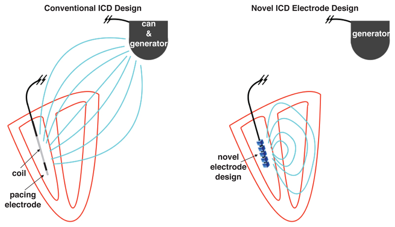
Conventional electrode (ICD) arrangements usually assign one polarity to the intra-cardiac lead (coil) within the right-ventricular (RV) cavity (with an extra-cardiac can, or ground) placed beneath the clavicle), which may switch sign during a shock in order to more efficiently defibrillate [28], [29], [30]. Alternative arrangements have an additional ground in the superior vena cava. In the case of a cathodal intra-cardiac polarity, wavefronts are initiated on the endocardium and in the case of anodal polarity, wavefronts are initiated on the epicardium [30] (due to respective direction of movement of charge carriers which cause VE effects). The large distance between the anode and cathode in typical ICD arrangements causes the potential to decay approximately isotropically from the intra-cardiac electrode, and the natural directionality of the shock-vector is lost. Furthermore, a significant proportion of the delivered shock energy is lost outside the heart, causing extra-cardiac nerve and muscle stimulation resulting in considerable pain [31], [32]. The typical use of an ICD for defibrillation via the RV coil and delivery of ATP from the RV lead tip is shown in Figure 1 (left).
Figure 1.
Schematic representation of conventional ICD electrode configuration (left) and proposed novel ICD electrode configuration (right). In the conventional ICD during a defibrillation shock, the RV coil is used to generate an electric field with shock vector between the coil and the can as the ground (field shown as light blue lines), thus generating significant extra-cardiac field and a lack of directionality. The tip of the RV coil acts as a pacing electrode when delivering ATP. In the proposed novel configuration, the RV electrode generates a field which is confined within the heart and is steerable, not requiring the generator to act as a ground.
A similar situation (of stray electric fields) exists in the case of novel low-energy defibrillation techniques [24], [18], whereby the shock vectors are also restricted to the physical placement of the electrodes within an ICD (which may involve the placement of additional electrodes in the coronary sinus); success of these methods may be significantly increased by being able to preferentially direct the shock vectors through the main organising centres of the reentrant activity. Thus, there is a strong need for steerable electrotherapy that may help to preferentially excite specific regions of the heart for use in both ATP and low-energy defibrillation therapies. In this work, we propose intra-cardiac electrode configurations which facilitate the stimulation of regions of myocardium in a precise way and confine the electric current to the immediate vicinity of the heart; stray (extra-cardiac) electric fields are thus minimized by design. A schematic of the idea behind our proposed configuration is shown in Figure 1 (right). Given knowledge of the location of the reentrant circuit, we suggest that the proposed electrode configurations could be used to direct the main VE depolarizations to be proximal to and/or within the reentrant circuit, in order to perform targeted ATP and/or defibrillation.
We demonstrate the feasibility of our proposed electrode configurations within idealised geometries and demonstrate the ability of directed tissue depolarization within a realistic rabbit ventricular geometry.
II. Methods
In order to analyse the electric field in detail, we solved Laplace’s equation (1)
| (1) |
with constant Dirichlet boundary conditions on charged surfaces (the anode and cathode electrodes) and no-flux conditions elsewhere via the finite element method, using the FENICS finite element solver [33], [34].
To examine effects of the fields generated by the electrodes on a realistic rabbit heart geometry we solve the passive steady-state bidomain equations [35]
| (2) |
| (3) |
| (4) |
via the finite element method, using the cardiac arrhythmia research package (CARP) [36]. In equations (4) σi is the intracellular conductivity tensor, σe is the extracellular conductivity tensor, ϕi is the intracellular potential, ϕe is the extracellular potential, β = 0.14 μm−1 is the surface-to-volume ratio, Vm is the transmembrane potential, Rm = 1 Ωm2 is the membrane resistance, σb = 1.0 S/m [37] is the conductivity of the bath, ϕb is the potential in the bath-space and the domains Ωt,b refer to the tissue and bath-space, respectively. The boundary conditions on the bidomain equations (4) are given as:
| (5) |
| (6) |
| (7) |
| (8) |
where n is the surface unit-normal vector and subscript tb refers to the tissue-bath interface. The intra and extracellular conductivities in the longitudinal and transverse directions were (σil, σit) = (0.17, 0.019) and (σel, σet) = (0.62, 0.24) S/m [38] respectively. The anode and cathode were represented by imposing dissimilar Dirichlet conditions on the appropriate boundaries.
A. Directional electrode configurations
By placing bi-polar electrodes inside the ventricular cavity, it is possible to excite the myocardium via VEs. Two different bi-polar directional stimulation electrode configurations, which create different electric fields, are described in the next section.
1). Bipole arrangement
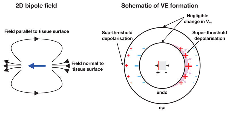
The bipole arrangement provides directional stimulation capability by exploiting the geometry of the ventricles, and the decay in field strength with increasing radius from the bipole source. If the stimulating electrode’s anode and cathode are both approximately colocated inside the ventricular cavity, the decay (approximately ∝ 1/r3 in the case of a dipole) in field strength as a function of the distance from the electrodes may be sufficient to facilitate stimulation on only one part of the endocardial surface, as illustrated in Figure 2. Although other types of bipolar electrodes are routinely used in cardiac pacing and electrophysiological measurement we believe that the specific arrangement proposed here, in the context of its application, is novel. In three dimensions the bi-polar arrangement would simply be an extension of the two-dimensional arrangement shown in Figure 2. With this electrode configuration, the decay in field strength is identical on either side of the bipole, thus the magnitudes of the surface VEs on the hyperpolarized and depolarized sides of the endocardium are equal.
Figure 2.
2D illustration of directional stimulation via bipolar intracardiac electrodes. Left: the electric field (black arrows) created by the bipole vector (blue arrow). Right: the schematic of operation of the bipole configuration. The gray region between the electrodes is an insulator. Super-threshold depolarization initiates wavefront propagation (shown via the magenta region) on one part of the endocardial surface. The sub-threshold depolarized epicardial surface (on the left side) does not initiate wavefront propagation. Surface VEs of negligible magnitude are created around the directions orthogonal to the direction of intended stimulation, due to the electric field vector being approximately tangent to the surface in these regions.
2). Bipole Halbach arrangement
The bipole Halbach arrangement provides directional stimulation capability in a conceptually different way to the bipole arrangement, in that it exploits the superposition of linear fields in order to reduce the field-strength in one direction and increase it in the opposite direction. Theoretically, this has the advantage of generating VEs on the proximal tissue surfaces of correspondingly different magnitudes.
The ability to provide direction-specific fields is widely-used in the field of magnetism and magnetic materials, originating from the so-called Halbach array. The design of the Halbach array was originally proposed by John Mallinson in 1973 [39], and then later independently by Klaus Halbach in the 1980s [40], [41] when it was applied to focus particle accelerator beams. The basic design involves an alternating pattern of permanent magnets which has the important effect of augmenting the magnetic flux on one side of the array, whilst the flux is cancelled on the other side (in the idealised setup). The concept is currently widely-used in many applications of manufacturing magnetic materials, from refrigerator magnets, through to magnetic drug targeting and particle accelerators. To our knowledge, such a design has not yet been applied to electrostatics, and particularly not within the field of cardiac anti-arrhythmia therapy.
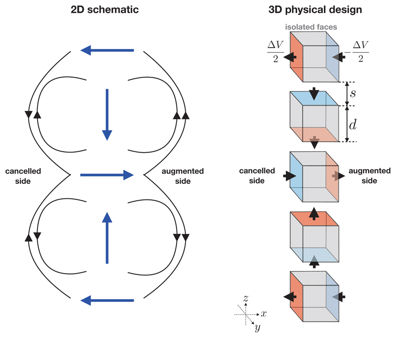
Unlike in a magnetic Halbach array, electrodes must not physically touch in order to stop a direct short-circuit from occurring. Therefore, some minimum physical separation must be introduced; the dependence of the current draw on this separation is investigated later. The simplest Halbach electrode configuration is formed of five electrode cubic “elements” equally spaced along a common axis. In order to achieve current steering in increments of π/2, each electrode element must comprise six conducting faces, each of which may be set to some potential or isolated from the rest of the circuit. Pairs of faces on each electrode element are parallel to one another and the axes formed by these pairs form an orthonormal basis. Opposite polarities are applied to each electrode pair. The simplest geometrical configuration of a Halbach electrode is shown in Figure 3. It can be seen from Figure 3 that the bipole vector rotates in increments of ψ = π/2 between electrode elements. The minimum number of electrode elements for the configuration shown in Figure 3 is nπ/ψ +1 where n = 2, however more can be added provided that n is integer. The material comprising the interior of each electrode element must be an insulator in order to force the potential to drop through the blood thus facilitating the superposition of the fields created by each electrode element. The direction of the cancelled and augmented sides may be swapped by either swapping the polarities of the 2nd and 4th elements, or the 1st, 3rd and 5th elements. The signs of the VEs induced in the tissue may be swapped by swapping the polarity of all the charged surfaces in the Halbach electrode configuration, facilitating charge burping in a similar manner to conventional biphasic defibrillation methods [30]. In the configuration shown in Figure 3, the field is augmented on the +x side and attenuated on the −x side, however it is important to note that, alternatively, ±y faces could be charged on the 1st, 3rd and 5th elements (instead of ±x, as shown) which would lead to augmentation/attenuation in the y-direction.
Figure 3.
Left: a two-dimensional schematic of the electric field (black arrows) produced by a Halbach bipole array showing the bipole vectors (blue arrows, pointing from positive to negative). Locally, the field directions point in the same direction on the right-hand-side of the bipole array and point in the opposite direction on the left-hand-side of the bipole array. Right: A three-dimensional design of a simple Halbach electrode configuration consisting of five cubic electrode “elements” arranged in a column, parameterized by the electrode edge length d and spacing s. A potential difference of ΔV is applied between charged faces (shown with red and blue colours). Gray faces are not charged and are electrically isolated from the rest of the circuit. The black arrows show the direction of the electric current. The particular arrangement shown augments the electric field in the +x direction, and cancels it in the −x direction. The augmented and cancelled directions may be swapped either by swapping the polarities of the 2nd and 4th elements, or the 1st, 3rd and 5th elements.
In the next section, the computational models are described and the the resulting E field is then examined for these electrode configurations.
B. Computational models
1). Models for Laplace’s equation
We chose to create identical finite-element meshes to compare the fields from both of the electrode configurations. The domain was a cuboid of size 20 × 20 × 10 m3, the electrode elements had identical size d = 1 m and the spacing s was varied s ∈ {0.25, 0.5, 1.0, 2.0} m. The potential difference between bipole electrodes was fixed at ΔV = 1 V. Both electrode configurations possess half-symmetry and this was exploited in order to the minimize computational expense. The results were then reflected around the lower plane to effectively give a cubic domain of size 20 × 20 × 20 m3. The boundaries of the domain were sufficiently far from the electrode to minimize the the boundary effects of the no-flux condition. The meshes were generated via constructive solid geometry, using the CGAL [42] mesh generation interface in FENICS. Each mesh had ≈ 500k degrees of freedom and ≈ 2.5 million elements, and the edge length near the boundaries was approximately one quarter of the edge length elsewhere.
The current-draw of the electrode arrangements, as a function of the spacing s, was approximated by finding the total flux through all boundaries (signified by Γ−) with negative Dirichlet conditions: Γ− = {∂Ω: ϕ|∂Ω = −(ΔV)/2} via
| (9) |
Note that the factor 2 in front of the integral was because the solution was obtained in only half of the domain, due to symmetry.
2). Model for the bidomain equations
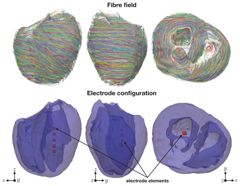
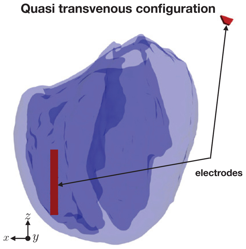
A five element electrode array (parameterized by s = d = 1 mm) was imposed in the middle of the left-ventricular cavity of the simplified version of the Oxford rabbit heart [43] using Tetgen [44]. We chose to use the simplified rabbit version in order to highlight the dominant effects of the surface VEs generated by the various electrode configurations. Figure 4 shows the rabbit geometry, the fibre field and the location of the electrodes inside the rabbit left ventricle. In both cases the potential difference between the anodal and the cathodal surfaces of each electrode element was 20 volts. The mesh had approximately 40 million elements and 670k degrees of freedom. The ventricles lie within a perfusing bath, extending just beyond the myocardium in each direction. For comparison, we also solved the steady-state bidomain equations for a quasi transvenous electrode setup, where one electrode lay near the right-ventricular apex and another lay at one edge of the computational domain as shown in Figure 5, again with an applied potential difference of 20 V.
Figure 4.
The fibre field, the rabbit geometry and the electrode configuration for the steady-state bidomain simulations. Note that the darker shade of blue in the lower panels corresponds to interior endocardial surfaces.
Figure 5.
The quasi transvenous electrode configuration.
III. Results
A. Solutions of Laplace’s equation
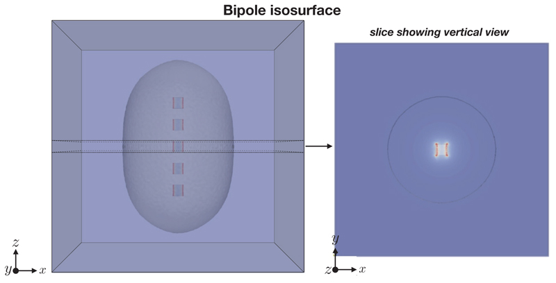
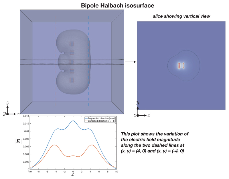
The electric field E = −∇ϕ (V/m) here is simply the gradient of the scalar potential ϕ satisfying Laplace’s equation (1). The characteristic shapes of |E| for the bipole and bipole Halbach configuration, are shown in Figures 6 and 7 respectively. It can be seen that the bipole configuration gives an approximately circular isosurface profile, whereas the bipole Halbach configuration isosurface shows a lopsided profile.
Figure 6.
Bipole configuration isosurface showing |E| = 0.01 V/m.
Figure 7.
Bipole Halbach configuration isosurface showing |E| = 0.01 V/m. The variation of the electric field in the z direction, along two sampling lines, is shown in the lower panel.
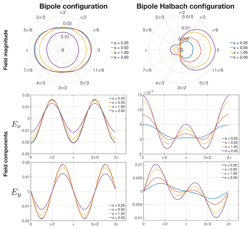
The variation in |E|, Ex = −∂ϕ/∂x and Ey = −∂ϕ/∂y at a radius of 4 m along a ring at z = 0 m around the origin are shown in Figure 8. The trends in the variation of the field magnitude and its components were substantially similar at different radii. Ez = −∂ϕ/∂z is not shown as it is zero due to the symmetry in the configuration.
Figure 8.
The electric field magnitude (shown in the polar plot via the radial axis) and its Ex and Ey components at a radius of 4 m along a ring at z = 0 around the origin, for different electrode element spacings s (with units of meters) with all other parameters fixed (d, ΔV).
Figure 8 shows that the field magnitude is symmetrical about x and y for the bipole array, whereas it is asymmetrical for the bipole Halbach array. The main lobe is at θ = 0 in the bipole Halbach array, with a small side lobe at θ = π. It can be seen that as s increases, |E| decreases in the bipole array whereas |E| increases in the Halbach bipole array.
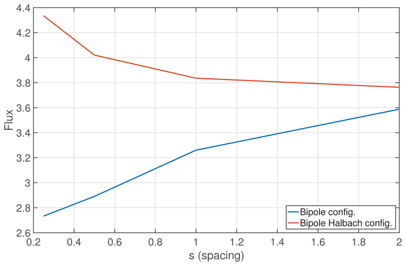
Figure 9 shows the total flux through Γ− as a function of the spacing s, for both electrode configurations. The total flux increases as s increases, for the bipole configuration, whereas the total flux decreases as s increases, for the bipole Halbach configuration. The increase in flux for smaller spacings in the bipole Halbach configuration is due to the increase in proximity of dissimilar Dirichlet boundaries. The decrease in flux for smaller spacings in the bipole configuration is most likely due to the electrode arrangement becoming more similar to that of a single cuboid, and thus reducing the strong current density at the sharp edges of adjacent electrode elements. Specifically, as s → 0, the large current-densities which occur due to the high curvature of the corners of the three inner cuboids gradually decrease, and then vanish, as each of the five cuboidal elements merge to become one single cuboid. In both configurations, it is expected that the flux would become equal as s → ∞ as the influence of the fields from neighbouring fields vanishes.
Figure 9.
The total flux, in units of Volt meters, through the surface defined by Γ−, as a function of the spacing s, for the bipole and bipole-Halbach configurations.
In the next section, the performance of the directional stimulation electrodes for stimulating the rabbit left ventricle, via VEs, is investigated.
B. Solutions of the the bidomain equations
Having demonstrated the overall profile of the electric fields for the different electrode configurations above, here the ability of these configurations to direct stimulation to induce asymmetrical effects on the endocardial surface within a rabbit ventricular model, via VEs, is investigated.
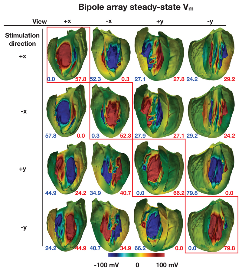
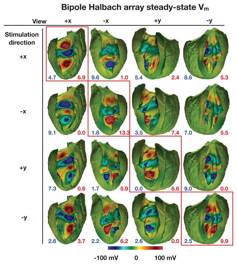
In the following sections, steady-state Vm (the VEs) are shown on the endocardial surfaces in the +x and −x and y+ and y− directions. These surfaces were formed by the bisection of the geometry by two planes which bisected each of the electrode elements and were parallel with the y axis and normal to the x axis, and parallel with the x axis and normal to the y axis, respectively. The Figures 10 and 11 show the endocardial surfaces arranged in a matrix, with those surfaces along the main diagonal (highlighted by red boxes) showing the VE in the stimulated direction. Here, by “stimulated direction”, we mean the direction which should theoretically cause the strongest depolarizations. In addition, the surface area of those triangular elements with VE magnitudes at all vertices of the triangles greater than 100 mV are shown via the annotations at the bottom of the figure panels.
Figure 10.
Steady-state surface Vm for the bipole configuration with a varying stimulation direction for an applied potential difference of 20 V. The numbers quoted show the total surface area (in mm2) of VEs with a magnitude greater than 100 mV (blue shows hyperpolarization and red shows depolarization).
Figure 11.
Steady-state surface Vm for the bipole Halbach configuration with a varying stimulation direction for an applied potential difference of 20 V. The numbers quoted show the total surface area (in mm2) of VEs with a magnitude greater than 100 mV (blue shows hyperpolarization and red shows depolarization).
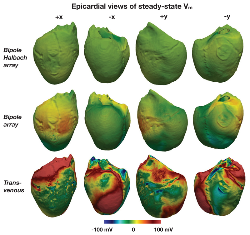
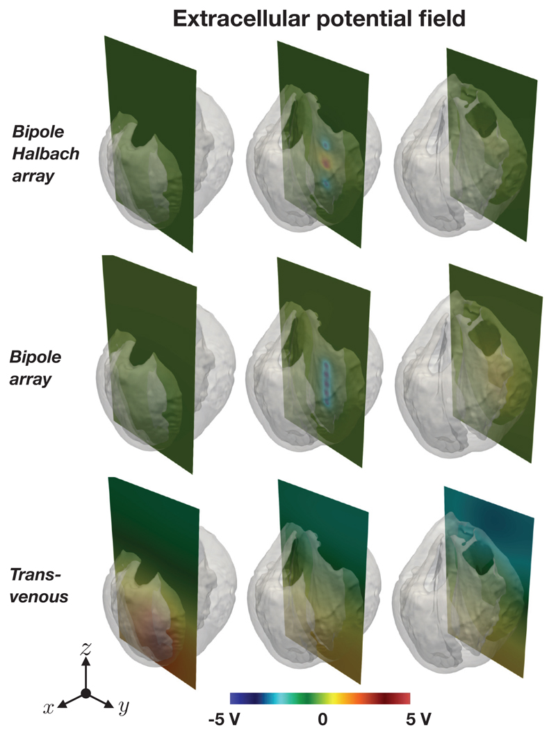
Figure 12 shows the epicardial VEs for both directional electrode configurations along with the the quasi-transvenous “conventional” setup, for comparison. Figure 13 shows the bath and extracellular potential distribution resulting from the electrode setups.
Figure 12.
Epicardial steady-state surface Vm for the two conceptual intracardiac directional electrode configurations and the quasi-transvenous configuration. In both the directional electrode configurations the “stimulated direction” was +x, and in each case tḥe applied potential difference was 20 V
Figure 13.
Extracellular potential distributions (ϕe and ϕb) along slices in different parts of the domain for the two conceptual intracardiac directional electrode configurations (top and middle) and the quasi-transvenous configuration (bottom). In both the directional electrode configurations the “stimulated direction” was +x, and in each case tḥe applied potential difference was 20 V
a). Bipole configuration
Figure 10 shows the VEs formed by the bipole electrode configuration with different stimulated directions. A strongly depolarized Vm in the stimulated direction (main diagonal), and a strongly hyperpolarized Vm in the opposite direction is observed in each case. The transmembrane potential around the middle of the surfaces in the non-stimulated direction is approximately zero in each case. This is due to the electric field in this direction being approximately tangent to the surface. For each row (each “stimulated direction”) the surface area of the triangles with VEs of greater than 100 mV are largest along the main diagonal, as expected. Areas of strong depolarization in orthogonal directions to the main stimulated direction are approximately half that shown in the main stimulated direction - again this is consistent with the results shown in Figures 8 and 6.
b). Bipole Halbach configuration
Figure 11 shows the VEs formed by the bipole Halbach configurations with different stimulated directions. In each case, in the stimulated direction (along the main diagonal), relatively strong depolarizations can be seen both near the apex and near the base, with a relatively strong hyperpolarization near the middle.
Strong VEs can also be seen in the non-stimulated directions. These spuriously strong VEs are a result of the irregularly shaped endocardial surface, and the non-uniform distance from the tissue surface to the electrode elements. If the geometry of the myocardium was that of a cylinder with its axis coincident with the bipole Halbach electrode arrangement, only weak VEs would be observed in directions other than the stimulated direction. Note that the color scales chosen in Figures 10 & 11 were specifically to aid direct comparison between the induced Vm distributions upon shock application in both configurations.
Furthermore, for the chosen applied voltage difference of 20 V we can see relatively strongly depolarised and hyperpolarised regions; such areas may well be susceptible to break excitations upon shock cessation (if using an active cell model). However, we emphasise that the magnitude of these polarisations is entirely dependant upon the prescribed potential difference, which may be adjusted to attenuate or augment these effects, as required.
For each row (each ‘stimulated direction’) the surface area of the triangles with VEs of greater than 100 mV are largest along the main diagonal, however the surface area is in some cases only sightly larger than in other (non-stimulated) directions. This is in part due to the crude design of the Halbach electrode, in part due to the imprecise positioning of the electrode array in the centre of the ventricular cavity, and also because of the heterogeneous nature of the endocardial surface.
c). Epicardial virtual electrodes
Figure 12 shows the VEs on the epicardial surfaces for the two intracardiac directional electrode configurations (in both cases the “stimulated direction” was in the +x direction), along with the quasi transvenous electrode configuration. It can be seen that epicardial VEs are suppressed well for the intracardiac configurations, whereas strong regions of depolarization are present in many areas in the case of the quasi transvenous shock.
d). Extracellular potential distribution
Figure 13 shows the extracellular potential distribution for the two intracardiac directional electrode configurations (in both cases the “stimulated direction” was in the +x direction), along with the quasitransvenous electrode configuration along three vertical slices located in the right-ventricle, in the left ventricle (near the intracardiac electrodes) and at the edge of the left ventricular wall. In the cases of the directional intracardiac electrode configurations, it can be seen that the extracellular potential decays rapidly with distance from the electrodes, whereas for the quasi-transvenous configuration the potential field extends beyong the heart, as expected.
IV. Discussion
Directional stimulation via two different intra-cardiac electrode configurations has been described. The two electrode configurations are intended to work in different ways; the bipole configuration is designed to cause widespread depolarizations on a specific parts of the endocardium, whereas the bipole Halbach configuration is designed to concentrate the electric field magnitude in one specific direction, thereby creating stronger (depolarized and hyperpolarized) VEs in the targeted direction. The results from the bidomain simulations show that, in the realistic heart geometry, the bipole arrangement causes greater surface depolarizations in the targeted direction (Figure 10), compared with the bipole Halbach arrangement (Figure 11). The designs proposed used bipole electrode pairs in close proximity - the fields generated by these bipole pairs are therefore similar to dipole fields, thus the decay in field strength is approximately proportional to 1/r3. This means the electric fields generated decay rapidly with distance from the electrodes, confining the majority of the field to the heart tissue, and reducing the likelihood of causing extra pain from useless extra-cardiac stimulation. It should be noted that these electrode configurations may also be operated in a conventional manner by applying the same potential to all faces of the electrode elements, and the applying the opposite potential to body of the sub-clavicle pulse generator.
The utilization of an ability to direct stimulation to a particular part of the ventricles must rely on knowing where the reentrant arrhythmia in question is centred (i.e. where the reentrant circuit may be). Such information could potentially be obtained a priori from contrast-enhanced magnetic resonance scans, making the key assumption that the circuit would always be centred within the areas of scar in myocardial infarction patients. Thus, the electrodes could be programmed to always deliver stimuli directed towards the suspected area of scar. In the cases when it is not known where the arrhythmia may originate, the electrodes themselves may be used to sense and locate the reentrant circuit in real-time, prior to pointing the far field stimulus. Utilising local electric field information is currently being used in the latest electroanatomical mapping systems to allow inference of underlying wavefront directions [45], whilst initial promising results have been shown in the localization of focal VTs using the electrodes on a standard transvenous ICD [46]. The multitude of orthogonal bipole pairs present in each of the electrode configurations may facilitate sensing of the extracellular potential, and thus the electric field, during the tachyarrhythmia. In theory, given a sufficiently intelligent signal processing technique, the location of the reentrant core may be estimated to some degree of accuracy, and used to send the correct signals to the conducting surfaces of the electrode elements in order to direct the stimulation. Assuming the activation wavefront originates in the ventricular cavity in which the electrode array is placed, then simply measuring the electric field (produced by the activation wavefront) at each of the electrode elements may give a reasonable approximation of the direction of wavefront propagation, and therefore the wavefront source.
It remains to be investigated whether or not the electrode arrangements can, in practice, perform targeted ATP in a human heart. In order to be practical, the lead must be sufficiently thin to be implantable via catheterisation and sufficiently robust enough to cope with the harsh mechanical environment inside the heart. A sufficiently robust lead may be difficult to manufacture, as, in the case of the bipole array a minimum of four channels are required to allow for targeted depolarization in angular increments of π/2, whereas in the case of the bipole Halbach array a minimum of six channels are required to perform current steering in similar angular increments. Smaller angular increments are of course possible with different designs, but this would require more channels to be carried in the lead. Other practical limitations include the precise positioning of the electrode in the ventricular cavity.
The physical design of the two electrode configurations may be modified in order to make them more amenable to implantation, by placing all the conducting surfaces on the surface of a cylinder, similar to what is done with the surface conductors (coils) routinely used in defibrillation leads. This would be trivial to achieve for the bipole configuration, but more complicated for the bipole Halbach configuration; perhaps the axially aligned bipole vectors may be approximated via ring electrode patches. Practically implantable designs were not tested in the current study due to limitations in the accurate meshing and application of boundary conditions to surfaces.
Future bidomain simulations should be performed using an active cell membrane and should investigate the actual performance of the undirectional stimulation electrodes at targeted ATP and defibrillation efficacy. Future simulations should also investigate the optimal placement of the electrode arrays inside the heart.
Also, only the extent of surface VEs were examined in this study as it is known that surface depolarizations decay exponentially with depth away from the tissue surface. However tissue anisotropy is also known to cause counterintuitive in-depth VEs via bidomain effects. The sinusoidally varying electric field formed by the bipole Halbach electrode configuration may elicit some weak deep entry VE effect first described in [47] due to the relative similarity of the idealized fibre architecture in [47], [48] with that of the real ventricular wall. Furthermore, the potential use of the Halbach array in ATP may involve the induction of multiple paced wavefronts from different endocardial locations (due to the multiple areas of depolarisation formed, as in Figure 11). Delivery of ATP from > 1 site has been shown to more effectively terminate sustained VT [49], [50].
An alternative application of the bipole Halbach array may be in field of deep brain stimulation, where directional electrodes are routinely employed [51], [52]. To the best knowledge of the authors, there are no directional stimulation electrodes which concentrate the current density in one direction and actively reduce the current density in the other.
V. Conclusions
Two directional stimulation electrode concepts have been described and tested in-silico in a rabbit heart. Strong targeted depolarizations via surface VEs have been shown with varying degrees of directional accuracy. Such electrode configurations may facilitate targeted far-field ATP, where the excitable gaps in the reentrant circuit are rapidly extinguished via wavefronts from VEs, directed towards the reentrant circuit. The multiple orthogonal pairs of conducting surfaces on the electrode elements may also facilitate the approximation of the local extracellular field, potentially facilitating the spatial localization of the reentrant core using the same electrode configurations that are then used to apply the directional stimulation. The electrode configurations may also be operated in a conventional manner, by setting all conducting surfaces to the same potential. Other potential biological applications of the bipole Halbach electrode may be in targeted deep brain stimulation.
VI. Limitations
The governing equations used neglect all physical non-linearities [53] occurring at the interface between the electrode surfaces and the colloidal electrolyte (blood), although it is thought that the influence of these effects will not change the structure of the electric fields generated. While we intentionally chose to use the simplified Oxford rabbit [43] to highlight the effects of the directional stimulation electrodes, this geometry does not include the papillary muscles [54] and the coronary vasculature [55], [24] which are known to create additional VE sources upon field stimulation. It is thought that break excitations [56], [54] near hyperpolarized boundaries may reduce the directional efficacy of the bipole arrangement, however this is thought to be of lesser significance for the bipole Halbach arrangement, due to the theoretically lower virtual-electrode magnitudes created in the non-augmented directions by the Halbach configuration. This is in contrast to the bipole arrangement, where all points (apart from where the field is tangent to the heart surface) experience a similar current-density. As described earlier, it may be feasible to calibrate the shock voltage to minimize the chance of breakexcitations in the non-excited directions. We also highlight that fact that the size of the regions of depolarisation and hyperpolarisation induced by these setups is relatively large, and thus their utility in providing a means of focussed stimulation of isolated areas may be limited. However, the induced polarisation patterns which the presented configurations are able to produce (combined with the fact that they can be ‘steered’ the preferentially affect different regions of the heart) suggest their potential for use in ATP in which the entire region close to the core of the reentrant circuit (usually the scarred area in myocardial infarction) can be targeted to terminate the arrhythmia. Finally, we emphasise also that the practical utility of the electrode arrays presented in this study will require further investigation in order to optimise the augmentation and modulation of the electric field with respect to specific electrode placement and the anatomical complexity of a real (human scale) heart.
Acknowledgements
This work was supported by the National Institute for Health Research Biomedical Research Centre at Guy’s and St. Thomas’ National Health Foundation Trust and King’s College, in addition National to the Centre of Excellence in Medical Engineering funded by the Wellcome Trust and Engineering and Physical Sciences Research Council (EPSRC; WT 088641/Z/09/Z). The views expressed are those of the author(s) and not necessarily those of the National Health Service, and the National Institute for Health Research, or the Department of Health. The authors acknowledge the British Heart Foundation through a KCL Pump-Priming Award and project grant number PG/14/66/30927, and the KCL Cardiovascular Healthcare Technology Cooperative.
References
- [1].Peinado R, Almendral J, Rius T, Moya A, Merino JL, Martinez-Alday J, Pérez-Villacastin J, Arenal A, Ormaetxe J, Tercedor L, Medina O, et al. Randomized, prospective comparison of four burst pacing algorithms for spontaneous ventricular tachycardia. Am J Cardiol. 1998;82(11):1422–1425. doi: 10.1016/s0002-9149(98)00654-7. [DOI] [PubMed] [Google Scholar]
- [2].Schaumann A, Mühlen Fvz, Herse B, Gonska B-D, Kreuzer H. Empirical versus tested antitachycardia pacing in implantable cardioverter defibrillators. Circ. 1998;97(1):66–74. doi: 10.1161/01.cir.97.1.66. [DOI] [PubMed] [Google Scholar]
- [3].Wathen MS, Sweeney MO, DeGroot PJ, Stark AJ, Koehler JL, Chisner MB, Machado C, Adkisson WO. Shock reduction using antitachycardia pacing for spontaneous rapid ventricular tachycardia in patients with coronary artery disease. Circ. 2001;104(7):796–801. doi: 10.1161/hc3101.093906. [DOI] [PubMed] [Google Scholar]
- [4].Santini M, Lunati M, Defaye P, Mermi J, Proclemer A, del Castillo-Arroys S, Molon G, Santi E, De Santo T, Navarro X, Kloppe A. Prospective multicenter randomized trial of fast ventricular tachycardia termination by prolonged versus conventional anti-tachyarrhythmia burst pacing in implantable cardioverter-defibrillator patients-atp delivery for painless icd therapy (advance-d) trial results. J Intervent Cardiac Electrophysiol. 2010 Mar;27(2):127–135. doi: 10.1007/s10840-009-9454-z. [DOI] [PMC free article] [PubMed] [Google Scholar]
- [5].Kleber AG, Rudy Y. Basic mechanisms of cardiac impulse propagation and associated arrhythmias. Physiol Rev. 2004;84(2):431–488. doi: 10.1152/physrev.00025.2003. [DOI] [PubMed] [Google Scholar]
- [6].Haghjoo M, Hajahmadi M, Fazelifar AF, Sadr-Ameli MA. Efficacy and safety of different antitachycardia pacing sites in the termination of ventricular tachycardia in patients with biventricular implantable cardioverter-defibrillator. Europace. 2011 Mar;13(4):509–513. doi: 10.1093/europace/euq513. [DOI] [PubMed] [Google Scholar]
- [7].Gasparini M, Anselme F, Clementy J, Santini M, Martinez-Ferrer J, Santo TD, Santi E, Schwab JO. Bi-ventricular versus right ventricular antitachycardia pacing to terminate ventricular tachyarrhythmias in patients receiving cardiac resynchronization therapy: The ADVANCE CRT-D Trial. Am Heart J. 2010;159(6):1116–1123. doi: 10.1016/j.ahj.2010.02.007. [DOI] [PubMed] [Google Scholar]
- [8].Allessie M, Kirchhof C, Scheffer GJ, Chorro F, Brugada J. Regional control of atrial fibrillation by rapid pacing in conscious dogs. Circ. 1991;84(4):1689–1697. doi: 10.1161/01.cir.84.4.1689. [DOI] [PubMed] [Google Scholar]
- [9].Roth BJ, Krassowska W. The induction of reentry in cardiac tissue. The missing link: How electric fields alter transmembrane potential. Chaos. 1998;8(1):204–220. doi: 10.1063/1.166298. [DOI] [PubMed] [Google Scholar]
- [10].White JB, Walcott GP, Pollard AE, Ideker RE. Myocardial discontinuities: a substrate for producing virtual electrodes that directly excite the myocardium by shocks. Circ. 1998;97(17):1738–1745. doi: 10.1161/01.cir.97.17.1738. [DOI] [PubMed] [Google Scholar]
- [11].Efimov IR, Aguel F, Cheng Y, Wollenzier B, Trayanova N. Virtual electrode polarization in the far field: implications for external defibrillation. Am J Physiol Heart Circ Physiol. 2000;48(3):H1055. doi: 10.1152/ajpheart.2000.279.3.H1055. [DOI] [PubMed] [Google Scholar]
- [12].Roth BJ, W JP, Jr, et al. Electrical stimulation of cardiac tissue: a bidomain model with active membrane properties. IEEE TBME. 1994;50(3):232–240. doi: 10.1109/10.284941. [DOI] [PubMed] [Google Scholar]
- [13].Lim H, Cun W, Wang Y, Gray RA, Glimm J. The role of conductivity discontinuities in design of cardiac defibrillation. Chaos. 2018;28(1):013106. doi: 10.1063/1.5019367. [DOI] [PubMed] [Google Scholar]
- [14].Efimov IR, Cheng Y, Yamanouchi Y, Tchou PJ. Direct Evidence of the Role of Virtual Electrode Induced Phase Singularity in Success and Failure of Defibrillation. J Cardiovasc Electrophysiol. 2007;11(8):861–868. doi: 10.1111/j.1540-8167.2000.tb00065.x. [DOI] [PubMed] [Google Scholar]
- [15].Efimov IR, Gray RA, Roth BJ. Virtual electrodes and deexcitation: new insights into fibrillation induction and defibrillation. J Cardiovasc Electrophysiol. 2007;11(3):339–353. doi: 10.1111/j.1540-8167.2000.tb01805.x. [DOI] [PubMed] [Google Scholar]
- [16].Sharifov OF, Fast VG. Role of intramural virtual electrodes in shock-induced activation of left ventricle: Optical measurements from the intact epicardial surface. Heart Rhythm. 2006 Sep;3(9):1063–1073. doi: 10.1016/j.hrthm.2006.05.018. [DOI] [PubMed] [Google Scholar]
- [17].Hooks DA, Trew ML, Smaill BH, Pullan AJ. Do Intramural Virtual Electrodes Facilitate Successful Defibrillation? Model-Based Analysis of Experimental Evidence. J Cardiovasc Electrophysiol. 2006 Mar;17(3):305–311. doi: 10.1111/j.1540-8167.2006.00360.x. [DOI] [PubMed] [Google Scholar]
- [18].Janardhan A, Li W, Fedorov V, Yeung M, Wallendorf M, Schuessler R, Efimov I. A novel low-energy electrotherapy that terminates ventricular tachycardia with lower energy than a biphasic shock when antitachycardia pacing fail. JACC. 2012;60:2393–2398. doi: 10.1016/j.jacc.2012.08.1001. [DOI] [PMC free article] [PubMed] [Google Scholar]
- [19].J AH, MD, Gutbrod SR, Li W, Lang D, Schuessler RB, Efimov IR. Multistage Electrotherapy Delivered Through Chronically-Implanted Leads Terminates Atrial Fibrillation WithLower Energy Than a Single Biphasic Shock. JAC. 2013 Dec;63(1):40–48. doi: 10.1016/j.jacc.2013.07.098. [DOI] [PMC free article] [PubMed] [Google Scholar]
- [20].A CM, R CM, E IR, F VV. Termination of sustained atrial flutter and fibrillation using low voltage multiple shock therapy. Heart Rhythm. 2011;8(1):101–108. doi: 10.1016/j.hrthm.2010.10.018. [DOI] [PMC free article] [PubMed] [Google Scholar]
- [21].Li W, Ripplinger CM, Lou Q, Efimov IR. Multiple monophasic shocks improve electrotherapy of ventricular tachycardia in a rabbit model of chronic infarction. Heart Rhythm . 2009 Jul;6(7):1020–1027. doi: 10.1016/j.hrthm.2009.03.015. [DOI] [PMC free article] [PubMed] [Google Scholar]
- [22].Bittihn P, Luther G, Bodenschatz E, Krinsky V, Parlitz U, Luther S. Far field pacing supersedes anti-tachycardia pacing in a generic model of excitable media. New J Physics. 2008 Oct;10(103012) [Google Scholar]
- [23].Boccia E, Luther S, Parlitz U. Modelling far field pacing for terminating spiral waves pinned to ischaemic heterogeneities in cardiac tissue. Phil Trans Roy Soc. 2017;375(2096) doi: 10.1098/rsta.2016.0289. [DOI] [PMC free article] [PubMed] [Google Scholar]
- [24].Luther S, Fenton FH, Kornreich BG, Squires A, Bittihn P, Hornung D, Zabel M, Flanders J, Gladuli A, Campoy L, Cherry E, et al. Low-energy control of electrical turbulence in the heart. Nature. 2012 Apr;475(7355):235–239. doi: 10.1038/nature10216. [DOI] [PMC free article] [PubMed] [Google Scholar]
- [25].Fenton FH, Luther S, Cherry EM, Otani NF, Krinsky V, Pumir A, Bodenschatz E, Gilmour RF. Termination of Atrial Fibrillation Using Pulsed Low-Energy Far-Field Stimulation. Circ. 2009 Aug;120(6):467–476. doi: 10.1161/CIRCULATIONAHA.108.825091. [DOI] [PMC free article] [PubMed] [Google Scholar]
- [26].Pumir A, Nikolski V, Hörning M, Isomura A, Agladze K, Yoshikawa K, Gilmour R, Bodenschatz E, Krinsky V. Wave emission from heterogeneities opens a way to controlling chaos in the heart. Phys Rev Lett. 2007 Nov;99:208101. doi: 10.1103/PhysRevLett.99.208101. [DOI] [PubMed] [Google Scholar]
- [27].Rantner L, Tice B, Trayanova N. Terminating ventricular tachyarrhythmias using far-field low-voltage stimuli: Mechanisms and delivery protocols. Heart Rhythm. 2013;10:1209–17. doi: 10.1016/j.hrthm.2013.04.027. [DOI] [PMC free article] [PubMed] [Google Scholar]
- [28].Daubert JP, Sheu S-S. Mystery of Biphasic Defibrillation Waveform Efficacy. JACC. 2008 Sep;52(10):836–838. doi: 10.1016/j.jacc.2008.05.041. [DOI] [PubMed] [Google Scholar]
- [29].Tang W. A Comparison of Biphasic and Monophasic Waveform Defibrillation After Prolonged Ventricular Fibrillation. Chest. 2001 Sep;120(3):948–954. doi: 10.1378/chest.120.3.948. [DOI] [PubMed] [Google Scholar]
- [30].Kroll MW, Swerdlow CD. Optimizing defibrillation waveforms for ICDs. J Intervent Cardiac Electrophysiol. 2007 Jun;18(3):247–263. doi: 10.1007/s10840-007-9095-z. [DOI] [PubMed] [Google Scholar]
- [31].Jayam V, Zviman M, Jayanti V, Roguin A, Halperin H, Berger RD. Internal defibrillation with minimal skeletal muscle activation: A new paradigm toward painless defibrillation. Heart Rhythm. 2005;2(10):1108–1113. doi: 10.1016/j.hrthm.2005.06.030. [DOI] [PubMed] [Google Scholar]
- [32].Roth BJ. Michael Faraday and painless defibrillation. Heart Rhythm. 2005;2(10):1114–1115. doi: 10.1016/j.hrthm.2005.07.005. [DOI] [PubMed] [Google Scholar]
- [33].Logg A, Mardel KA, Wells G. Automated Solution of Differential Equations by the Finite Element Method. 2012 [Google Scholar]
- [34].Alnaes M, Blechta J, Hake J, Johansson A, Kehlet B, Logg A, Richardson C, Ring J, Rognes M, Wells G. The fenics project version 1.5. Arch Num Soft. 2015;3(100) [Google Scholar]
- [35].Henriquez CS. Simulating the electrical behavior of cardiac tissue using the bidomain model. Crit rev biomed eng. 1992;21(1):1–77. [PubMed] [Google Scholar]
- [36].Vigmond E, Hughes M, Plank G, Leon LJ. Computational tools for modeling electrical activity in cardiac tissue. J Electrocardiol. 2003 Dec;36:69–74. doi: 10.1016/j.jelectrocard.2003.09.017. [DOI] [PubMed] [Google Scholar]
- [37].Visser K. Electric conductivity of stationary and flowing human blood at low frequencies. Eng Med Biol Soc. 1989;5:1540–2. doi: 10.1007/BF02446796. [DOI] [PubMed] [Google Scholar]
- [38].Clerc L. Directional differences of impulse spread in trabecular muscle from mammalian heart. J Physiol. 1976;255(2):335–346. doi: 10.1113/jphysiol.1976.sp011283. [DOI] [PMC free article] [PubMed] [Google Scholar]
- [39].Mallinson J. One-sided fluxes - A magnetic curiosity? IEEE Trans Magnet. 1973;9(4):678–682. [Google Scholar]
- [40].Halbach K. Design of permanent multipole magnets with oriented rare earth cobalt material. Nuc Inst Meth. 1980;169(1):1–10. [Google Scholar]
- [41].Halbach K. Applications of permanent magnets in accelerators and electron storage rings. J App Phys. 1985;57(1):3605–3608. [Google Scholar]
- [42].Alliez P, Jamin C, Rineau L, Tayeb S, Tournois J, Yvinec M. CGAL User and Reference Manual. 4.11.1 ed. CGAL Editorial Board; 2018. 3D mesh generation. [Google Scholar]
- [43].Bishop MJ, Plank G. The role of fine-scale anatomical structure in the dynamics of reentry in computational models of the rabbit ventricles. J Physiol. 2012 Sep;590(18):4515–4535. doi: 10.1113/jphysiol.2012.229062. [DOI] [PMC free article] [PubMed] [Google Scholar]
- [44].Si H. Tetgen, a delaunay-based quality tetrahedral mesh generator. ACM Trans Math Softw. 2015 Feb;41(2):11:1–11:36. [Google Scholar]
- [45].Deno DC, Balachandran R, Morgan D, Ahmad F, Masse S, Nanthakumar K. Orientation-independent catheter-based characterization of myocardial activation. IEEE Trans Biomed Eng. 2017 May;64(5):1067–1077. doi: 10.1109/TBME.2016.2589158. [DOI] [PubMed] [Google Scholar]
- [46].Chaumeil A, Sacher F, Casset C, Qu F, Mcspadden L, Derval N, Denis A, Hocini M, Jais P, Haissaguerre M. Can an icd determine the origin of focal vt. EP Europace. 2017;19(3):108. [Google Scholar]
- [47].Otani NF. Deep entry of defibrillating effects into homogeneous cardiac tissue. IEEE Trans Biomed Eng. 2004 Mar;51(3):401–407. doi: 10.1109/TBME.2003.820995. [DOI] [PubMed] [Google Scholar]
- [48].Patel SG, Roth BJ. Approximate solution to the bidomain equations for defibrillation problems. Phys Rev E. 2005 Feb;71:021908. doi: 10.1103/PhysRevE.71.021908. [DOI] [PubMed] [Google Scholar]
- [49].Byrd IA, Kay MW, Pollard AE. Interactions Between Paced Wavefronts and Monomorphic Ventricular Tachycardia: Implications for Antitachycardia Pacing. J Cardiovasc Electrophysiol. 2006 Oct;17(10):1129–1139. doi: 10.1111/j.1540-8167.2006.00579.x. [DOI] [PubMed] [Google Scholar]
- [50].Byrd IA, Rogers JM, Smith WM, Pollard AE. Comparison of Conventional and Biventricular Antitachycardia Pacing in a Geometrically Realistic Model of the Rabbit Ventricle. J Cardiovasc Electrophysiol. 2004 Sep;15(9):1066–1077. doi: 10.1046/j.1540-8167.2004.03672.x. [DOI] [PubMed] [Google Scholar]
- [51].Butson CR, McIntyre CC. Current steering to control the volume of tissue activated during deep brain stimulation. Brain Stimulation. 2008;1(1):7–15. doi: 10.1016/j.brs.2007.08.004. [DOI] [PMC free article] [PubMed] [Google Scholar]
- [52].Timmermann L, et al. Multiple-source current steering in sub-thalamic nucleus deep brain stimulation for Parkinson’s disease (the VANTAGE study): a non-randomised, prospective, multicentre, open-label study. The Lancet Neurology. 2018;14(7):693–701. doi: 10.1016/S1474-4422(15)00087-3. [DOI] [PubMed] [Google Scholar]
- [53].Lau EW. 11 - leads and electrodes for cardiac implantable electronic devices. In: Ellenbogen KA, Wilkoff BL, Kay GN, Lau C-P, Auricchio A, editors. Clinical Cardiac Pacing, Defibrillation and Resynchronization Therapy (Fifth Edition) fifth edition ed. Elsevier; 2017. pp. 313–351.e29. [Google Scholar]
- [54].Connolly A, Robson MD, Schneider J, Burton R, Plank G, Bishop MJ. Highly trabeculated structure of the human endocardium underlies asymmetrical response to low-energy monophasic shocks. Chaos. 2017;27(9):093913. doi: 10.1063/1.4999609. [DOI] [PMC free article] [PubMed] [Google Scholar]
- [55].Pumir A, Krinsky V. Unpinning of a rotating wave in cardiac muscle by an electric field. J Theor Biol. 1999;199(3):311–319. doi: 10.1006/jtbi.1999.0957. [DOI] [PubMed] [Google Scholar]
- [56].Kandel MS, Roth BJ. The strength-interval curve in cardiac tissue. Comp Math Meth Med. 2013;1:11. doi: 10.1155/2013/134163. [DOI] [PMC free article] [PubMed] [Google Scholar]


