Abstract
BACKGROUND AND PURPOSE: Cochlear implantation requires introduction of a stimulating electrode array into the scala vestibuli or scala tympani. Although these structures can be separately identified on many high-resolution scans, it is often difficult to ascertain whether these channels are patent throughout their length. The aim of this study was to determine whether an optimized combination of an imaging protocol and a visualization technique allows routine 3D rendering of the scala vestibuli and scala tympani.
METHODS: A submillimeter T2 fast spin-echo imaging sequence was designed to optimize the performance of 3D visualization methods. The spatial resolution was determined experimentally using primary images and 3D surface and volume renderings from eight healthy subjects. These data were used to develop the imaging sequence and to compare the quality and signal-to-noise dependency of four data visualization algorithms: maximum intensity projection, ray casting with transparent voxels, ray casting with opaque voxels, and isosurface rendering. The ability of these methods to produce 3D renderings of the scala tympani and scala vestibuli was also examined. The imaging technique was used in five patients with sensorineural deafness.
RESULTS: Visualization techniques produced optimal results in combination with an isotropic volume imaging sequence. Clinicians preferred the isosurface-rendered images to other 3D visualizations. Both isosurface and ray casting displayed the scala vestibuli and scala tympani throughout their length. Abnormalities were shown in three patients, and in one of these, a focal occlusion of the scala tympani was confirmed at surgery.
CONCLUSION: Three-dimensional images of the scala vestibuli and scala tympani can be routinely produced. The combination of an MR sequence optimized for use with isosurface rendering or ray-casting algorithms can produce 3D images with greater spatial resolution and anatomic detail than has been possible previously.
MR imaging is increasingly used in the examination of patients with sensorineural hearing loss (1). The popularity of the investigation initially resulted from the exquisite sensitivity of contrast-enhanced T1-weighted MR imaging in the demonstration of acoustic neuroma. Recent improvements in MR methodology have led several workers to examine the feasibility of submillimeter high-resolution T2-weighted imaging of the inner ear and internal auditory meatus (2). Many of these studies have been directed toward the detection of small intracanalicular acoustic neuromas without the need for contrast enhancement. Several groups have also established the ability of high-resolution T2-weighted imaging to show the endolymph and perilymph cavities of the inner ear itself (1, 3–8).
The use of T2-weighted imaging offers the opportunity for diagnosis and preoperative assessment of patients with congenital or acquired vestibulocochlear disease. This is of particular relevance in the planning of cochlear implantation, in which detailed preoperative assessment of cochlear morphology is important. One previous report has examined the usefulness of MR imaging in measuring the transverse diameter of the cochlear nerve, which is known to correspond closely to the remaining number of spiral ganglion cells in the cochlea itself (9). While this approach may reduce the instance of unsuccessful implantations in ears with severe denervation, the success of implantation also depends on the presence of a patent cochlear fluid channel for electrode insertion.
The anatomy of the cochlea has recently been elegantly reviewed in this Journal (10). It is a coiled structure of 2¾ turns containing three parallel fluid canals, an outer scala vestibuli (ascending spiral), an inner scala tympani (descending spiral), and the central, smaller, cochlear duct (scala media). Electrode implantation is usually performed by insertion of an electrode array into the scala tympani or scala vestibuli (2). This process may be complicated or prevented by malformation of the cochlea or by fibrotic or osseous obstruction of one or both fluid channels. Obstruction is particularly common as a sequela to meningitis or labyrinthitis, in which the occlusion may be due to fibrosis or to the formation of ectopic bone that may obliterate the fluid-filled channels necessary for implant insertions.
Cochlear imaging with spiral CT produces images of the bony labyrinth that are of extremely high spatial resolution (2) but that may fail to show fibrotic occlusions (11). The use of MR imaging may increase the specificity with which such fibrotic occlusions are demonstrated but involves a procedure for which the patient may require sedation or even a general anesthetic (2). Furthermore, most surgeons are unwilling to completely replace CT with MR imaging, so that the patient would require both. The use of MR imaging can therefore be justified only if it proves capable of providing diagnostic information that is superior to that obtained with CT. It is this consideration, combined with cost, that has prevented MR imaging from becoming a routine investigation in the planning of cochlear implantation.
T2-weighted MR sequences produce images in which the scala vestibuli and scala tympani can be distinguished separately, at least in the region of the basal turn. This ability to distinguish the cochlear fluid cavities may represent one specific advantage of MR imaging in the planning of cochlear implantation. Despite this, to our knowledge, all 3D renderings of cochlear MR images that have appeared in the literature incorrectly depict the cochlea as a single fluid structure (1, 4–8, 12, 13). We believe that this reflects both the imaging protocols and the visualization techniques used to produce 3D renderings. In many cases, the requirement for high in-plane resolution combined with acceptable signal-to-noise (S/N) ratios has led to the use of highly nonisotropic voxels. This would be expected to adversely affect the performance of 3D rendering techniques, which may in fact be relatively insensitive to otherwise unacceptable levels of image noise. In addition, many methods of 3D visualization are available, some of which may be more appropriate for use in this type of application. At a basic level, 3D visualization methods are divided into surface-rendering and volume-rendering classes. Surface-rendering techniques identify 3D contour lines on the basis of image intensity and use these to define the surface of a 3D object, which can then be viewed. Volume-rendering methods use the data from many or all the pixels in a volume to produce a 3D rendering. This technique may be thought of as viewing the shadow of a partially transparent object in which the relative opacities of the contents and the direction of the illumination may be controlled.
The aim of this study was to determine whether an optimized combination of an MR imaging protocol and a data visualization technique is capable of routinely rendering as separate structures the scala vestibuli and scala tympani for preoperative planning of cochlear implantation.
Methods
Imaging Studies
Imaging was performed in eight healthy volunteers (four women and four men) aged 20 to 27 years. All images were acquired on a 1.5-T Philips Medical Systems ACS NT scanner. The petrous bone was localized using T1-weighted localizer images in all three cardinal planes. The position of the vestibule and cochlea was then identified using a series of 3-mm-thick coronal T2-weighted fast spin-echo (FSE) images (TR/TE = 3000/150, echo train length [ETL] = 128). All localization images were obtained with the use of a head coil.
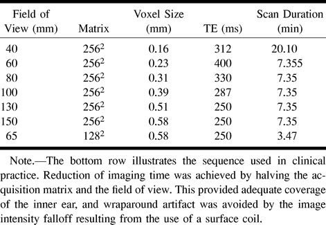
Imaging of the inner ear was performed with a 3-inch-diameter flexible circular surface coil positioned over the external auditory meatus by means of a flexible-arm coil holder. A series of T2-weighted volume acquisitions was obtained. Common imaging parameters are shown in Table 1. The effect of varying the ETL was investigated in volunteers 1 and 2. The restrictions on TE and field of view (FOV) of increasing the ETL are given in Table 2. After completing this study, the effect of varying the voxel volume was investigated in the remaining six subjects (volunteers 3–8) using a fixed ETL of 45. The effective voxel sizes used in this experiment are shown in Table 3. The image data from the six volunteers formed the basis for all assessments of image quality and comparisons of visualization techniques.
Table 1:
Imaging parameters used in all high-resolution T2-weighted images
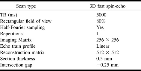
Table 2:
Range of echo train lengths used in the study
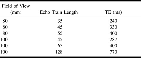
Table 3:
Fields of view and other imaging parameters used in the study
Data Visualization
Visualization Techniques
Images were transferred to an independent workstation (Sun Microsystems, SPARC 20) and data visualization was performed using the Application Visualization System (AVS 5, AVS/Uniras, Copenhagen, Denmark) software package. Data were prepared by interactive cropping of the image volume to include only the inner ear structures in order to reduce the processing time required to the minimum possible in each case. Volume visualization was performed using the following four methods: 1) the maximum intensity projection (MIP) algorithm, 2) the ray-casting technique with voxel opacity adjusted to allow transparency of the data block, 3) the ray-casting technique with opaque voxels to produce a surface rendering, and 4) the isosurface rendering technique using Lorenson's marching cubes algorithm (14).
To enable direct comparison of the visualization techniques, 3D images of the cochlea were produced from each data set from volunteers 3 through 8 (n = 36). All visualization techniques were used to produce a standard projection to show the inner ear structures. Standardized threshold values of 65% of peak vestibular endolymph signal intensity were selected for methods 3 and 4 (vide infra).
Measurements and Statistics
Effect of Voxel Size on Image Quality
The inherent image contrast on the primary images was calculated objectively for each scan. Measurements of signal intensity were made following transfer of images to a viewing console (Easy Vision, Philips Medical Systems). Measurements of pixel intensity (mean and SD) were taken from the vestibule and from an adjacent area of bone using a standard circular 50-pixel region of interest. Image contrast (C) was calculated as
 |
where C = image contrast, Vest = mean pixel intensity from the vestibule, sdvest = SD of pixel intensities from the vestibule, bone = mean pixel intensity from bone, and sdbone = SD of pixel intensities from bone.
In addition, two experienced neuroradiologists assessed all primary images and reconstructions from volunteers 3 through 8. Image quality was scored on a simple subjective scale as 1 = nondiagnostic, 2 = poor, 3 = acceptable, 4 = good, and 5 = excellent.
Scores for primary images were assessed from hard copies taken from each scan protocol (Table 3) in the six volunteers at the level of the cochlear modiolus. Scores for volume visualization images were assigned for each rendering technique for each data set from the standard previously prepared projection viewed on the workstation console.
Interobserver agreement was assessed using Cohen's κ statistic with weighted estimations of κ. Subjective scores between groups were compared using Fisher's exact test for contingency tables (15).
Comparison of Visualization Techniques
Following initial scoring and comparison of the visualizations at different voxel sizes, the optimally rendered images from each technique were compared using the same scoring system. Images were examined on a workstation and users were allowed to rotate the renderings in three dimensions but not to perform any other interactions. Users were asked to assess the quality of each rendering in terms of anatomic detail and overall quality and to rank the four visualizations (methods 1 through 4) for each patient (1 = best, 4 = worst). To assess the acceptability of these images, the comparison was performed by a large group of 15 physicians (five consultant and six trainee radiologists, and two consultant and two trainee otolaryngologists) who had not previously seen any of the rendered images. All the observers had experience in examining images of the inner ear on CT scans, and four had experience in viewing MR images.
Determination of Threshold Values
The optimal method for objective determination of threshold values for visualization methods 3 and 4 was also assessed using data from volunteers 3 through 8. The intensity threshold values were based on measurements of the signal intensity of vestibular endolymph from the primary images. A series of threshold values was calculated using each of two techniques: 1) The first threshold series was calculated using the measurements of the mean and SD of the vestibular endolymph signal intensity; a range of standard threshold values was then calculated starting at the mean value plus 1 SD and progressively increasing by half of 1 SD. 2) The second threshold series was calculated as a proportion of the peak vestibular endolymph signal intensity calculated from a single region of interest placed over the vestibule on a central image. The range of threshold values extended from 50% to 80% of the peak value in 5% increments. Comparisons of isosurface renderings from each of the six data sets in each of six volunteers (n = 36 studies) at given thresholds were used to assess the reproducibility of these two thresholding techniques.
Visualization of Cochlear Fluid Cavities
Separate visualization of the cochlear fluid cavities was attempted using all four visualization techniques. Decreases in voxel opacity using method 2 and increases in the surface threshold using methods 3 and 4 were used to reduce the contribution of peripheral, partial-volume-averaged pixels to the 3D display. The quality of these visualizations was judged subjectively by two of the authors. Assessment of image quality was based on the ability to see both the scala vestibuli and scala tympani throughout their length and on the evenness of reduction of the visualized structures as the parameters (opacity or threshold) were adjusted.
Patient Studies
Imaging in five patients undergoing assessment for cochlear implantation was used to test the feasibility of applying the imaging protocol in clinical cases. The group consisted of three boys and two girls, aged 2 to 8 years. All patients had become deaf as a sequela to meningitis. Imaging sequences were obtained with the parameters described above and an FOV of 130 mm. For clinical use, the acquisition matrix was reduced to 128 in the phase-encoding direction to reduce image acquisition time (Table 3). Using this sequence, imaging time was 3 minutes 47 seconds per ear. All five patients also were examined with CT using a high-resolution spiral technique (FOV, 250 mm2; matrix, 320 mm2; section thickness, 2 mm; pitch, −1 mm; reconstruction thickness, 1 mm; keV, 120; mA, 170). CT scans and primary MR images were reviewed independently by two consultant neuroradiologists.
Results
Primary Images
Interobserver agreement for subjective image assessment was good to excellent in all cases (κ .72 to .91). Comparison of images with variable ETL revealed both decreased image contrast and unacceptable image blurring with ETLs in excess of 45.
Varying the effective voxel size by manipulating the FOV resulted in maximal image contrast with a pixel size of 0.51 mm2 (FOV, 130 mm) (Figs 1 and 2). Subjective assessment of these images showed a significantly higher score for images with a pixel size of 0.39 mm2 (FOV, 100 mm; P < .01) (Fig 1). Visual comparison of these images revealed a slight subjective improvement in the depiction of the internal cochlear structures on images obtained with an FOV of 100 mm as compared with those obtained with an FOV of 130 mm. This increase in spatial resolution appeared to make the images more acceptable to the reporting radiologist, despite the lower inherent S/N ratio.
fig 1.
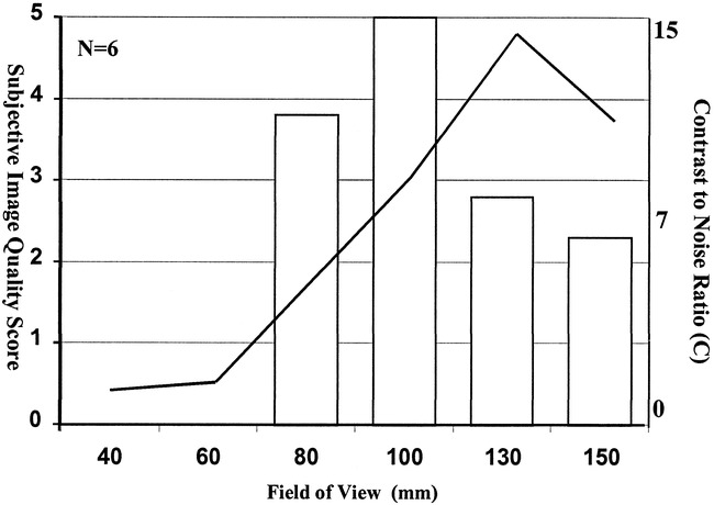
Histogram of the subjective primary image quality scores (left axis) at varying fields of view. The line plot represented on the right axis shows the mean value for calculated image contrast from six normal data sets
fig 2.
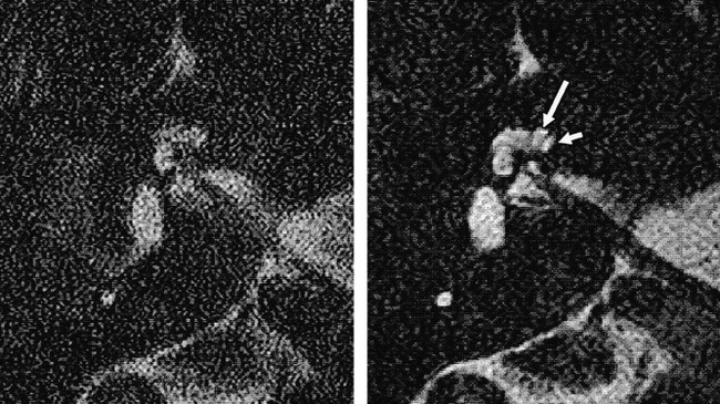
Samples of primary images from a healthy volunteer obtained using FOVs of 60 mm (left) and 130 mm (right). Note the improvement in S/N ratio with the larger FOV and the separate demonstration of the scala vestibuli (long arrow) and scala tympani (short arrow) in the basal turn of the cochlea
Visualizations
Effect of Voxel Size on Image Quality
Visualizations produced by the MIP algorithm showed consistently good scores at an FOV greater than 80 mm. Below this, images became nondiagnostic. As the FOV dropped below 80 mm, inner ear structures became indistinguishable from background (Figs 3A and 4).
fig 3.
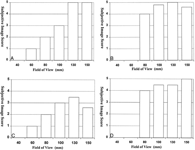
Histograms show the effect of changing FOV size on the subjective image quality scores for each visualization technique: method 1, MIP (A); method 2, ray casting with transparent voxels (B); method 3, ray casting with opaque voxels (C); and method 4, isosurface rendering (D). Scores are the average of six image sets, each scored by two observers
fig 4.
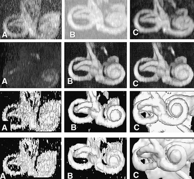
The effect of increasing S/N ratio on each of the four visualization techniques. Images labeled A (left column) are renderings from studies obtained with an FOV of 60 mm, images labeled B (middle column) are from studies obtained with an FOV of 100 mm, and images labeled C (right column) are from studies obtained with an FOV of 130 mm. Row 1 were rendered using method 1 (MIP), row 2 using method 2 (ray casting with transparent voxels), row 3 using method 3 (ray casting with opaque voxels), and row 4 with method 4 (isosurface rendering). The images show rapid degradation of visualization obtained with methods 1 and 4, as FOV and S/N ratio are reduced. Method 2 continues to produce excellent renderings at an FOV of 100 mm, with no apparent degradation as compared with images acquired at 130 mm
Visualizations produced by the ray-casting technique with transparent voxels (method 2) showed little deterioration as the contrast-to-noise ratio decreased. These visualizations were considered good with an FOV of 80 mm, although no rendering could be obtained with smaller FOVs (Figs 3B and 4).
Visualizations produced by the ray-casting technique with opaque voxels (method 3) were scored lower than other visualizations at all FOVs (Figs 3C and 4). The reason for this is unclear, although these renderings do show a rather marked banding effect on curved surfaces (Figs 4 and 5).
fig 5.
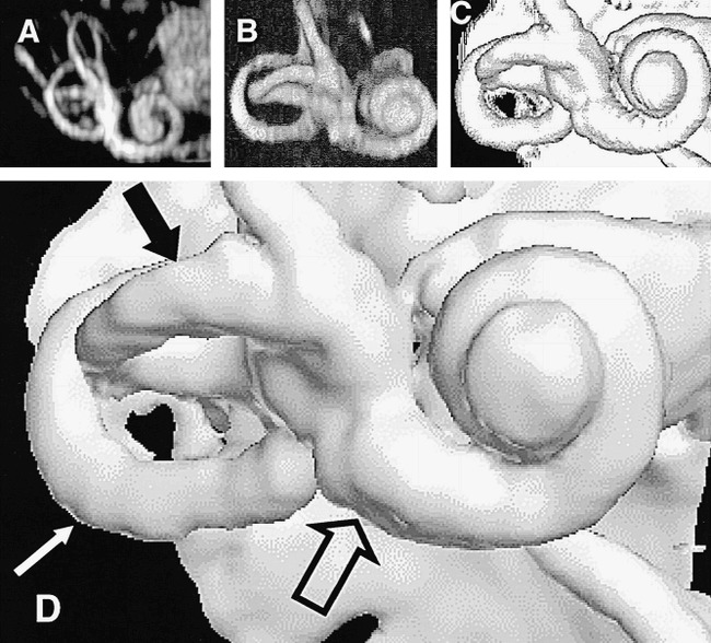
The results of the optimal combination of imaging and visualization technique in a single healthy subject (5000/250; FOV, 130 mm2; matrix, 2562). All renderings were derived from the same image data set.
A, Method 1: MIP.
B, Method 2: ray casting with transparent voxels.
C, Method 3: ray casting with opaque voxels.
D, Method 4: isosurface rendering (white arrow indicates the posterior semicircular canal; solid black arrow, the lateral semicircular canal; open arrow, the basal turn of the cochlea).
Visualizations produced by using the isosurface algorithm (method 4) were good to excellent on images with a high contrast-to-noise ratio (FOV greater than 100 mm) but showed quite marked quality reduction at FOVs below this level (Figs 3D and 4).
Comparison of Visualization Techniques
A comparison of the optimal quality renderings from each technique showed little difference in the subjective image quality scores among the four visualization techniques (method 1, 4.2; method 2, 4.8; method 3, 4.7; and method 4, 5.0). These differences were not statistically significant. Despite this, there was a clear preference for the isosurface-rendered images (method 4: mean rank, 1.3; P < .001) when users were asked to rank the visualization techniques. The transparent voxel ray-casting technique (method 2) and the opaque ray-casting technique (method 3) received similar ratings (mean rank, 2.6 and 2.8, respectively). The MIP technique (method 1) was most commonly rated lowest (mean rank, 3.7). Examples of the optimal volume visualization results with the four techniques are shown in Figure 5.
Determination of Threshold Values
The comparison of methods for determination of isosurface threshold values showed no consistency among renderings when the threshold was calculated from the mean and SD of the vestibular endolymph. Use of the peak value within the endolymph as a reference led to reproducible rendering across the patient group. With a threshold value of 65% of peak, the surface anatomy of the inner ear was clearly depicted (Fig 5), while increases to 75% and 80% produced reproducible images of the cochlear fluid cavities along their length.
Visualization of Cochlear Fluid Cavities
Cochlear fluid channels could not be distinguished on MIP visualizations in any case. Attempts to depict cochlear fluid channels by using manipulation of opacity values with the volume-rendering technique (ray casting, method 3) were also unsuccessful, and no image was considered clearly to show separate internal cochlear structures. Decreasing the opacity of fluid-containing voxels in the ray-casting algorithm used for method 2 did allow separate visualization of the scala vestibuli and scala tympani, as illustrated in Figure 6. The effect of increasing the isosurface extraction value with an isosurface-rendering algorithm is shown in Figure 7. Gradual increases in the extraction value led to increasing demarcation of the two major cochlear fluid channels. The use of endolymph values taken from a region of interest within the vestibule shows two fluid channels to be clearly visible at 75% and 85% of the peak signal intensity from vestibular endolymph (Fig 7C and D). Further elevation of the threshold value (>85%) produced artifactual obstructions in the scala vestibuli. This finding was typical for data sets from all six volunteers.
fig 6.
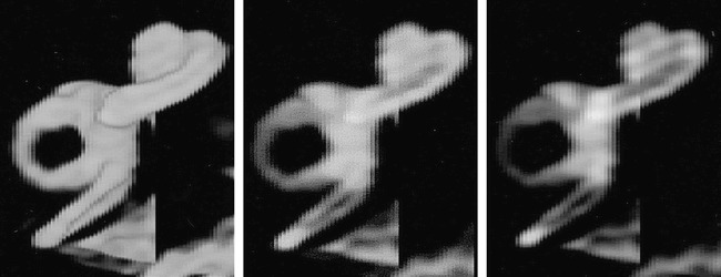
The effect of decreasing voxel opacity (right to left) using ray tracing. The images are volume renderings of the same normal data set using method 2 (ray casting with transparent voxels). The opacity values of the voxels have been progressively decreased from left to right in order to demonstrate more internal details of the cochlea. The scala vestibuli and scala tympani are clearly seen in the middle and right-hand images, although their margins are rather poorly defined
fig 7.
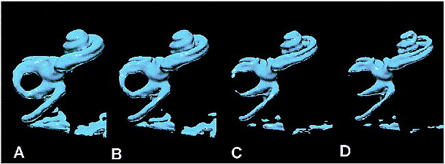
The effect of increasing the isosurface threshold with isosurface rendering (left to right). The images are isosurface renderings of the same normal data set. As the images pass from right to left, progressively higher threshold values have been applied to extract the isosurface. The isosurface in B corresponds to 65% of the peak signal intensity in the vestibule and is the value used for standardizations of isosurface renderings in the current study. Other renderings were obtained at 55% (A), 75% (B), and 85% (C). The scala vestibuli and scale tympani are clearly and separately depicted throughout their length in C and D.
Patient Studies
Findings on CT and primary MR studies were considered normal in four of five cases. In the fifth, some abnormality was noted in the region of the distal cochlear turns on MR images but not on CT scans. MR reconstruction quality was excellent in all five clinical cases. Isosurface renderings produced results directly comparable to those seen in healthy volunteers. Primary image quality was slightly improved, reflecting the smaller head size and closer positioning of the surface coil in this pediatric group. The cochlear fluid channels appeared irregular in all cases as compared with normal. In one case, a localized occlusion of the scala tympani was demonstrated (Fig 8), which was subsequently confirmed at surgery. Other cases showed no obstacle to electrode implantation, although a small island of abnormal tissue between the scala vestibuli and scala tympani was seen in one case (Fig 9A) and severe deformation of the tip of the distal turn of the cochlea was seen in another (Fig 9B).
fig 8.
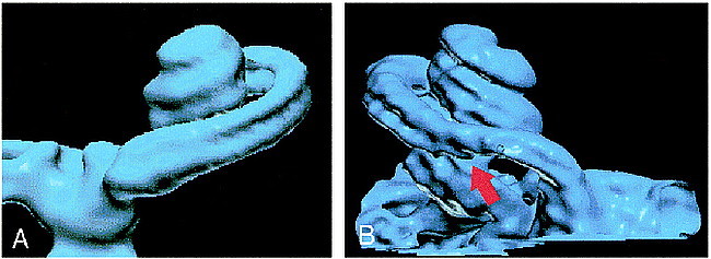
A and B, Normal (A) and abnormal (B) cochlea are shown for comparison. The scala tympani (arrow, B) is occluded as a sequela of meningitis
fig 9.
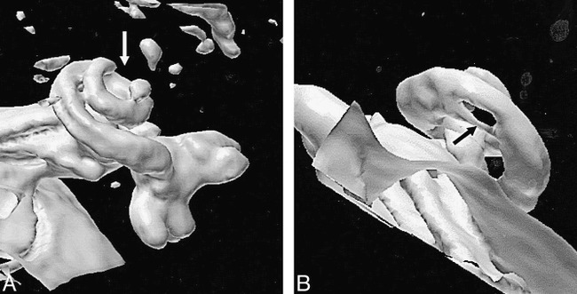
A and B, Two patients with abnormalities of the cochlea, caused by meningitis. Neither of the abnormalities was considered a contraindication to implantation, which was successfully conducted in both cases.
A, Patient with an occlusion of the terminal portion of the cochlea (arrow).
B, Patient with an abnormality just distal to the basal turn (arrow). Since CT findings were normal, this is assumed to represent a fibrotic narrowing of the cochlear fluid channels.
Discussion
Previous MR studies have produced submillimeter-resolution MR images of the inner ear using gradient-echo (16, 17) or FSE (4–6, 12, 18, 19) techniques. The theoretical benefits of thin-section gradient-echo images are outweighed by the complications of magnetic susceptibility–related signal loss due to the multiple fluid/bone interfaces seen within the petrous bone. These artifacts limit spatial resolution and decrease the available S/N ratio. They are particularly prominent in the region of the internal auditory canal, where small soft-tissue structures interface with surrounding bone and air (20, 21). These artifacts can be reduced to some extent by modification of the gradient-echo sequence (3D Fourier transformation constructive interference in steady state [FT-CISS]). This has been shown to provide high-quality images of inner ear disease (17, 22, 23) and has been suggested as a standard sequence for the imaging of the inner ear. Other workers (4–6, 12, 18, 19) have described the use of high-resolution FSE sequences for imaging of the inner ear. FSE techniques allow the filling of multiple lines of k-space during a single TR, resulting in a significant reduction in overall acquisition time. The use of multiple closely spaced 180° refocusing pulses diminishes magnetic susceptibility effects, reducing susceptibility artifacts, and resulting in maintenance of true T2 contrast rather than the T2* contrast characteristics of gradient-echo methods.
In developing our imaging protocol we attempted to obtain the maximal possible spatial resolution at acceptable S/N ratios for 3D visualization. The use of a dual-surface receiver coil system provides an inherently higher S/N ratio than standard head coils (24), and signal falloff outside the surface-coil FOV prevents significant wraparound artifacts. Since imaging was directed entirely at the inner ear, resolution was increased by reducing the FOV while using a fixed matrix size (256 × 256). A section thickness of 0.5 mm was selected in order to allow the production of approximately isotropic voxels within the range of the study. A comparison of our imaging sequences revealed optimal S/N ratio and image quality within a voxel size of 0.51 × 0.51 × 0.5 mm. The use of overcontiguous section acquisition (section gap, −0.25 mm) and data reconstruction with a 512 × 512 matrix resulted in an effective pixel size of 0.25 × 0.25 × 0.25 mm in the final data set. This compares favorably with previous studies done with gradient-echo (3) and FSE (1, 4, 5, 8, 12, 25) sequences, in which the minimum effective section thickness was 0.7 to 1.0 mm and in-section resolution was 0.4 to 0.66 mm. The combination of surface-coil acquisition, an ETL of 45, and a TR of 5000 meant that a 30-section acquisition could be performed in 7 minutes 35 seconds (5000/250; FOV, 130 mm2; matrix, 2562). Reduction of the FOV and of the matrix by 50% reduces scan time to 3 minutes 47 seconds with no significant reduction in image quality (5000/250; FOV, 65 mm2; matrix, 1282). This technique produces excellent subjective image quality despite the presence of higher noise levels than seen in images produced by other investigative groups (1, 5, 8).
The production of high-resolution data sets such as those described here can complicate the interpretation of complex anatomy from 2D sections. This has led several researchers to attempt 3D visualization of the volume data using an MIP technique (1, 3, 5, 8, 13). As this study shows, the MIP algorithm, although widely available on commercial image analysis workstations and familiar to most radiologists because of its use in CT and MR angiography, suffers from a number of significant disadvantages in displaying more complex data sets.
Volume visualization algorithms can be broadly classified as belonging to either the surface-rendering or volume-rendering category. With volume-rendering techniques (methods 1, 2, and 3), the voxels are projected onto the final image plane. One of the simplest direct techniques is MIP. The value for each pixel in the MIP algorithm is calculated by compositing all voxels lying along a line perpendicular to the image plane. The pixel with the highest composite value is used to derive a maximum intensity, which is mapped to white with all lesser value pixels mapped to lower points on the gray scale. Although this approach is attractive and computationally inexpensive, the MIP algorithm has a number of significant disadvantages (26). The major problem for the visualization of 3D objects stems from the fact that the gray scale is automatically derived from the composite pixel values. This means that thinner areas of a structure will automatically be mapped in darker shades. More important, small fluctuations in surface morphology may be insufficient to cause any change in the 3D representation, especially when they occur in pixels with large overall composite values. Similarly, the decrease in gray scale values at the edge of curved structures, such as the cochlea itself, gives rise to apparent blurring, which is subjectively unattractive. Ray-casting techniques were developed to address some of the problems of the MIP approach. Selecting opacity values on the basis of image intensity enables fine tuning of the technique, from the demonstration of all voxels in the volume (method 2) to the identification of isointensity surfaces (method 3) (27). This makes the production of 3D images of the cochlear perilymph channels straightforward, although objective standardization of the images among patients presents considerable problems. In addition, the technique is relatively slow, since it is usually implemented via software rather than hardware.
Surface-rendering techniques use voxel intensities to define 3D isocontours, which outline the boundaries of the object. These boundaries are then represented as solid surfaces for viewing (method 4). The position of the surface within the 3D volume sample is determined by selection of a threshold value or isosurface. The marching cubes technique used here (14) is a simple and elegant approach to creating 3D isosurfaces. The algorithm relies on internal look-up tables for polygon generation, which makes it highly efficient. Isosurface-rendered models of the cochlea can be generated and rotated in real time on conventional PC systems or low-end workstations.
The intrinsic interpolation that takes place in the generation of the isocontour surface produces a smooth rendering that is highly sensitive to variations in surface topography and that can be manipulated to show internal structures, such as the scala tympani and scala vestibuli. The disadvantage of the technique is that it is relatively sensitive to image noise, which can distort the generated isosurface. More important, since the model is opaque, areas of the 3D rendering may be obscured by the CSF surface of the posterior fossa or by fluid collections within the air cells of the petrous temporal bone. Because of the speed of the reconstruction, this can often be overcome either by increased cropping of the image or by rotation to obtain the desired view.
In the present study, both the ray-casting and isosurface approaches allowed separate demonstration of the scala vestibuli and scala tympani throughout their length. The higher computational speed and subjective preference for isosurface images have led us to adopt this technique for routine use in our center. While the purpose of the study was to examine the feasibility of producing visualizations of the fluid channels within the cochlea, we did not assess the clinical utility of these imaging techniques. In the five patients we studied, image and visualization quality was high and abnormalities were depicted in three cases. However, surgical confirmation of the MR findings was available in only one of the five cases, and CT failed to show abnormalities in any. It is clear that extensive clinical studies are required before MR imaging is adopted for routine investigation of cochlear abnormalities. We believe that these studies should specifically address the assessment of cochlear patency by using techniques such as the one we have described.
The production of high-quality 3D renderings of this type is dependent on a combination of optimal imaging and postprocessing techniques. The imaging parameters described herein are easily accommodated on most current-generation high-field MR scanning systems so that the production of adequate primary images should pose no significant problems. The postprocessing stage is also critical, and software selection is important. The current technique was developed with the use of standard algorithms implemented by means of a standard, commercial visualization software package (Application Visualisation System). Since the data sets are small, the procedure is largely memory-dependent, and we have been able to produce real-time isosurface renderings on a variety of hardware platforms, ranging from a Silicon Graphics Octane workstation to a 300-MHz PC with 128 MB of RAM. Our attempts to duplicate these rendering techniques on a variety of commercially available medical image analysis workstations have been largely unsuccessful. We believe this is the result of variations in the implementation of the surface-rendering algorithms; however, these details are not available for most commercial systems.
Conclusion
The use of a submillimeter high-resolution T2-weighted FSE technique can produce high-quality images of the fluid channels within the cochlea. Images covering the entire inner ear structure can be obtained in an acceptable time period. Volume-visualization techniques can significantly aid the interpretation of these images, and the isosurface and ray-casting techniques provide clinical data that are clearly superior to that obtained with traditional MIP algorithms.
Footnotes
This study forms part of the European Commission project: NOVICE (Network Oriented Visualisation in a Clinical Environment, ESPRIT Contract No: EP26342) and was also supported in part by Philips Medical Systems UK Ltd.
Address reprint requests to Professor A. Jackson, Department of Diagnostic Radiology, Stopford Medical School, Oxford Rd, Manchester, M13 9PT UK.
References
- 1.Lee JN, King BD, Parker DL, Buswell HR, Harnsberger HR. High resolution 3D imaging of the inner ear with a modified fast spin- echo pulse sequence. J Magn Reson Imaging 1996;6:223-225 [DOI] [PubMed] [Google Scholar]
- 2.Lo WM. Imaging of cochlear and auditory brain stem implantation. AJNR Am J Neuroradiol 1998;19:1147-1154 [PMC free article] [PubMed] [Google Scholar]
- 3.Casselman JW, Kuhweide R, Ampe W, et al. Inner ear malformations in patients with sensorineural hearing loss: detection with gradient-echo (3DFT-CISS) MRI. Neuroradiology 1996;38:278-286 [DOI] [PubMed] [Google Scholar]
- 4.Naganawa S, Yamakawa K, Fukatsu H, et al. High-resolution T2-weighted MR imaging of the inner ear using a long echo-train-length 3D fast spin-echo sequence. Eur Radiol 1996;6:369-374 [DOI] [PubMed] [Google Scholar]
- 5.Allen RW, Harnsberger HR, Shelton C, et al. Low-cost high-resolution fast spin-echo MR of acoustic schwannoma: an alternative to enhanced conventional spin-echo MR? [See comments]. AJNR Am J Neuroradiol 1996;17:1205-1210 [PMC free article] [PubMed] [Google Scholar]
- 6.Manfre L, Lagalla R, Ferrara S, Riggio E, Tortorici M, Cardinale AE. MRI of the inner ear: use of modified GRASS and fast spin-echo sequences, a preliminary study. Neuroradiology 1996;38:669-674 [DOI] [PubMed] [Google Scholar]
- 7.Casselman JW, Kuhweide R, Dehaene I, Ampe W, Devlies F. Magnetic resonance examination of the inner ear and cerebellopontine angle in patients with vertigo and/or abnormal findings at vestibular testing. Acta Otolaryngol Suppl (Stockh) 1994;513:15-27 [DOI] [PubMed] [Google Scholar]
- 8.Dahlen RT, Allen RW, Harnsberger HR. High resolution fast spin echo magnetic resonance imaging of the petrous bone. Int J Neuroradiol 1995;2:171-176 [Google Scholar]
- 9.Naito Y, Honjo I, Takahashi H, et al. Surface-coil magnetic resonance imaging of the internal auditory canal and the inner ear: preliminary report. Ann Otol Rhinol Laryngol 1995;104:776-782 [DOI] [PubMed] [Google Scholar]
- 10.Daniels DL, Swartz JD, Harnsberger HR, Ulmer JL, Shaffer KA, Mark L. Anatomic moment: hearing, I: the cochlea. AJNR Am J Neuroradiol 1996;17:1237-1241 [PMC free article] [PubMed] [Google Scholar]
- 11.Seidman DA, Chute PM, Parisier S. Temporal bone imaging for cochlear implantation. Laryngoscope 1994;104:562-565 [DOI] [PubMed] [Google Scholar]
- 12.Naganawa S, Itoh T, Fukatsu H, et al. Three-dimensional fast spin echo of the inner ear: ultra-long echo train length and half-Fourier techniques. AJNR Am J Neuroradiol 1998;19:739-741 [PMC free article] [PubMed] [Google Scholar]
- 13.Swartz J, Daniels D, Harnsberger H, Shaffer K, Leighton M. Balance and equilibrium, I: the vestibule and semicircular canals. AJNR Am J Neuroradiol 1996;17:17-21 [PMC free article] [PubMed] [Google Scholar]
- 14.Lorensen W, Cline H. Marching cubes: a high resolution 3D surface construction algorithm. ACM Comput Graphics 1987;21:163-170 [Google Scholar]
- 15.Altman D. Practical Statistics for Medical Research.. London: Chapman Hall; 1991
- 16.Schmalbrock P, Brogan M, Chakeres D, Hacker V, Ying K, Clymer B. Optimization of sub-millimeter resolution MR imaging methods for the inner ear. J Magn Reson Imaging 1993;32:451-459 [DOI] [PubMed] [Google Scholar]
- 17.Casselman J, Kuhweide R, Deimling M, Ampe W, Dehaene I, Meeus L. Constructive interference in steady state: 3DFT imaging of the inner ear and cerebellopontine angle. AJNR Am J Neuroradiol 1993;14:47. [PMC free article] [PubMed] [Google Scholar]
- 18.Tien RD, Felsberg GJ, Macfall J. Fast spin-echo high-resolution MR imaging of the inner ear. AJR Am J Roentgenol 1992;159:395-398 [DOI] [PubMed] [Google Scholar]
- 19.Dahlen RT, Harnsberger HR, Gray SD, et al. Overlapping thin-section fast spin-echo MR of the large vestibular aqueduct syndrome. AJNR Am J Neuroradiol 1997;18:67-75 [PMC free article] [PubMed] [Google Scholar]
- 20.Elster A. Sellar susceptibility artifacts: theory and implications. AJNR Am J Neuroradiol 1993;14:129. [PMC free article] [PubMed] [Google Scholar]
- 21.Jones K, Mulkern R, Schwartz R, Oshio K, Barnes P, Jolesz F. Fast spin echo imaging of the brain and spine: current concepts. AJR Am J Roentgenol 1992;158:1313-1320 [DOI] [PubMed] [Google Scholar]
- 22.Held P, Fellner C, Fellner F, et al. MRI of inner ear and facial nerve pathology using 3D MP-RAGE and 3D CISS sequences. Br J Radiol 1997;70:558-566 [DOI] [PubMed] [Google Scholar]
- 23.Held P, Fellner C, Fellner F, Seitz J, Strutz J. MRI of inner ear anatomy using 3D MP-RAGE and 3D CISS sequences. Br J Radiol 1997;70:465-472 [DOI] [PubMed] [Google Scholar]
- 24.Koenig H, Lenz M, Sauter R. Temporal bone region: high resolution MR imaging using surface coils. Radiology 1986;159:191-194 [DOI] [PubMed] [Google Scholar]
- 25.Takehara Y, Ichijo K, Tooyama N, Kodaira N, Fujiwara T, Nozaki A. Three-dimensional projection images of the labyrinth acquired with multislab 3DFT fast spin-echo sequence and dual-array surface coil. AJR Am J Roentgenol 1995;165:645-646 [DOI] [PubMed] [Google Scholar]
- 26.Westover L. Footprint evaluation for volume rendering: Siggraph 90 proceedings. Comput Graphics 1990;24:367-376 [Google Scholar]
- 27.Levoy M. Efficient ray tracing of volume data. ACM Trans Graphics 1990;9:245-261 [Google Scholar]


