Abstract
Summary: We describe a head tilt technique for use with CT angiography that reduces beam-hardening artifacts in patients with aneurysm clips. This simple maneuver directs the artifacts away from pertinent anatomy, thus increasing the chances for diagnostic accuracy. No significant changes in the CT angiographic protocol are required, and the maneuver can easily be combined with other artifact-minimizing strategies.
The frequency of multiple intracranial aneurysms has been reported to be 14% to 45%, with most authors indicating a frequency of 20% to 30% (1). Thus, after surgical treatment of an intracranial aneurysm, follow-up imaging of the remainder of the circle of Willis may be required. CT angiography has emerged as an effective noninvasive technique for assessing intracranial aneurysms (2, 3), but with the postoperative patient, metal artifacts can severely degrade image quality.
Technique and Representative Cases
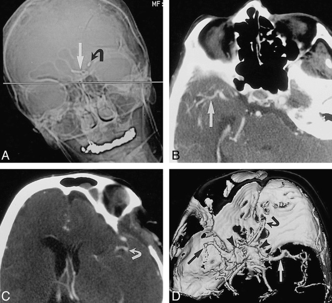
To improve the quality of CT angiograms in patients who have undergone aneurysm clipping, we developed a technique to diminish the effects of beam-hardening artifacts. The patient is placed supine on the CT examination table with the head within the head-holder. Using an anteroposterior digital scout image as a reference, we tilt the patient's head such that the axial plane through the aneurysm clip projects away from the remainder of the circle of Willis. The CT angiogram is then obtained with the patient maintaining the tilted head position. Figure 1 shows the use of this maneuver with the left middle cerebral artery above and the right middle cerebral artery below the plane of the beam-hardening artifact from the aneurysm clip. Since this technique only involves a change in the position of the head, acquisition of CT angiographic data and postprocessing methodology are otherwise routine (2, 3).
fig 1.

Tilted head position for intracranial CT angiography in a patient who has undergone clipping of multiple aneurysms.
A, Anteroposterior scout image of the head for planning CT angiography shows plane (straight line) for axial image acquisition (straight arrow indicates aneurysm clip in anterior communicating artery; curved arrow, aneurysm clip in carotid bifurcation). Note position of head should minimize image degradation, because metal artifact will project away from vessels of interest.
B and C, Axial source images from CT angiogram show right middle cerebral artery (arrow, B) and left middle cerebral artery (arrow, C) without interference from metallic beam-hardening artifact.
D, Shaded-surface-display image from CT angiogram viewed from above shows left (white arrow) and right (black arrow) middle cerebral artery without interference from aneurysm clip's beam-hardening artifact (arrowheads). Owing to limited z-axis coverage, left middle cerebral artery is abbreviated because examination was targeted to suspicious right middle cerebral artery. Current CT scanner software would allow coverage of entire head, tilted or not.
We have performed this technique in four patients with aneurysm clips. Two patients were being examined for presurgical planning for a known second aneurysm near the skull base. The other two cases were of more diagnostic significance, as CT angiography was being done to confirm the presence or absence (vessel loop) of an aneurysm that was questionable after retrospective review of prior conventional angiograms.
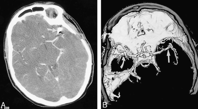
Among the latter two patients, one had clipped aneurysms of the left carotid bifurcation and anterior communicating artery and a suspicious right middle cerebral artery (Fig 1). The other patient had a clipped left middle cerebral artery aneurysm and a suspicious left anterior cerebral artery (Fig 2). In both cases, the CT angiogram obtained with the head tilt maneuver showed a vessel loop and no aneurysm, avoiding the need to repeat conventional angiography.
fig 2.

Tilted head position for intracranial CT angiography in a patient who has undergone clipping of a single aneurysm.
A, Axial source image from CT angiogram shows left middle cerebral artery aneurysm clipping (arrow) with adjacent metallic beam-hardening artifact.
B, Shaded-surface-display image from CT angiogram viewed from above shows right middle cerebral artery (straight arrow) without interference from aneurysm clip's beam-hardening artifact (curved arrow).
Discussion
In examining patients after intracranial aneurysm clipping, the options for evaluating the circle of Willis are limited. Noninvasive evaluation would require MR angiography or CT angiography, both of which are susceptible to image degradation by clip artifacts. Thus, conventional angiography remains the standard procedure for the preoperative and postoperative assessment of aneurysms. MR angiography is an option only if the aneurysm clip is MR-compatible. Documentation of compatibility is problematic, as untoward outcomes are possible even with close scrutiny (4). If the patient does undergo MR imaging, the susceptibility artifact from the metal clip will compromise image quality. The artifact is worst immediately adjacent to the clip, and it cannot easily be directed away from the remainder of the circle of Willis.
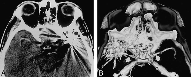
The thin collimation used in CT angiography tends to reduce image degradation from aneurysm clips. However, the extent of the artifact is not predictable and is not completely eliminated (Fig 3). Depending on the location of the aneurysm, the technique we describe lessens image degradation by directing the artifact away from the vessels of interest, further reducing the chance that the artifact will obscure important anatomy. With this easily performed technique, the remainder of the circle of Willis can be examined with minimal image degradation and without significantly altering the inherent axial CT resolution or the generation of shaded-surface-display or maximum-intensity-projection images. In the four patients in whom we performed this technique, the projectional images were adequate for diagnosis as well as for surgical planning. No important anatomy was lost. The concept is similar to the rationale behind the common practice of tilting the gantry in carotid CT angiography to avoid dental hardware. Our technique is also applicable in patients who have undergone aneurysm treatment with endovascular coils, which can also produce beam-hardening artifacts.
fig 3.

Standard head position for intracranial CT angiography.
A, Axial source image from CT angiogram shows degradation of image due to beam-hardening artifacts from clips (two) on left middle cerebral artery aneurysms.
B, Shaded-surface-display image from CT angiogram viewed from above shows middle cerebral arteries (arrows) and metallic beam-hardening artifact.
Conclusion
The head tilt technique is intended to maximize the quality of the image away from the aneurysm. When combined with subtraction and superimposition techniques, which allow examination of the clipped aneurysm itself (5), much of the postoperative circle of Willis is accessible to evaluation using CT angiography. Nevertheless, CT angiography in the postoperative patient is problematic, requiring further advancements in artifact reduction before it can reliably replace conventional angiography as the technique of choice.
Footnotes
Address reprint requests to James H. Brown, MD, Diagnostic Imaging of Elizabeth, 415 Morris Ave, Elizabeth, NJ 07208.
References
- 1.Armonda RA, NehIs DG. Multiple intracranial aneurysms. In: Carter LP, Spetzler RF, eds. Neurovascular Surgery. New York: McGraw-Hill; 1994:807–814
- 2.Alberico RA, Patel M, Casey S, et al. Evaluation of the circle of Willis with three-dimensional CT angiography in patients with suspected intracranial aneurysms. AJNR Am J Neuroradiol 1995;16:1571-1578 [PMC free article] [PubMed] [Google Scholar]
- 3.Vieco PT, Shuman WP, Alsofrom GF, et al. Detection of circle of Willis aneurysms in patients with subarachnoid hemorrhage: a comparison of CT angiography and digital subtraction angiography. AJR Am J Roentgenol 1995;165:425-430 [DOI] [PubMed] [Google Scholar]
- 4.Klucznik RP, Carrier DA, Pyka R, Haid RW. Placement of a ferromagnetic intracerebral: aneurysm clip in a magnetic field with fatal outcome. Radiology 1993;187:855-856 [DOI] [PubMed] [Google Scholar]
- 5.Vieco PT, Morin EE III, Gross CE. CT angiography in the examination of patients with aneurysm clips. AJNR Am J Neuroradiol 1996;17:455-457 [PMC free article] [PubMed] [Google Scholar]


