Abstract

Nanoparticle (NP)-stabilized foam technology has found potential applications in CO2 enhanced oil recovery (EOR) and greenhouse gas geological storage practices and accordingly attracts lots of research interest. To screen the optimal formula for the satisfactory foam performance, orthogonal experimental design (OED) is used in this paper for the complex multifactor multilevel system consisting of five influential factors of NP size, surfactant concentration, NP concentration, temperature, and salinity at four different levels in the range of 7–40 nm, 0–0.15 wt %, 0–0.2 wt %, 25–55 °C, and 0–3 wt %, respectively. Based on the orthogonal principle, only 16 experiments were performed to analyze the effect of various factors on the foam height and foam half-life properties. In addition to showing that the influence of the single factor on foam static properties, OED results reveal that the surfactant concentration and temperature are dominating factors on foamability and stability of the NP-stabilized CO2 foam, respectively. Finally, NP-stabilized CO2 foam with satisfactory static characteristics is obtained with the OED recommended composition of a 0.15 wt % surfactant concentration, 0.1 wt % NP concentration, and NP size of 7 nm in 1 wt % saline solution at temperatures of 30 and 50 °C, validating that the OED method could substantially facilitate the laboratory screening and optimization process for a successful NP-stabilized CO2 foam application.
1. Introduction
The enhancement technology for oil recovery has become increasingly important with the continued exploration of underground oil reserves. The CO2 flooding process can not only significantly enhance oil production but also, in the meantime, economically and efficiently store large-scale greenhouse gas in the tight underground formations. Therefore, it has attracted lots of interest from researchers in recent years.1−4
Due to the low viscosity and density, the injected CO2 is highly prone to gas channeling and gravity segregation in underground formations, which results in low sweep efficiency of the reservoir.5,6 A popular way of CO2 mobility control is to generate foam in situ with surfactant solutions, which can significantly improve the sweep efficiency and accelerate the rate of CO2 dissolution in the oil phase by increasing the contact area between the oil and CO2.7−11 There are obvious disadvantages, however, for the surfactant-based CO2 foam, such as it can be easily defoamed after being exposed to crude oil under reservoir conditions and easily decomposed under high temperature and high salinity conditions.12 Therefore, it is of great practical significance to improve the stability of the CO2 foam system for its potential field applications.
It has been demonstrated in the past decade that solid particles can effectively improve the foam stability;13−15 and with the development of nanotechnology, nanoparticles (NPs) have been identified as effective foam stabilizers in enhanced oil recovery (EOR) applications with high stability and persistence.16−18 Since NPs have certain solid particle characteristics compared to the surfactant, the film formed by the adsorption of NPs at the gas–liquid interface has higher mechanical strength and thus enhances the stability of the foam. The NPs adsorbed at the gas–liquid interface can form a spatial network structure to reduce the direct contact between the fluids, thereby acting as a barrier to the liquid discharge and gas diffusion to prevent membrane cracking and bubble coarsening.19−22
To evaluate foam generation and stability properties of the NP-stabilized foam system, however, comprehensive laboratory tests have to be performed considering quite a few influential factors, such as NP surface wettability, NP concentration, NP sizes, NP types, presence of oil, temperature, pressure, salinity, gas type, and so on.23 The accommodation of so many influential factors in one set of laboratory tests, therefore, becomes a challenging task. Up to now, most researchers employed the separate control variable method in their studies, that is, varying one parameter of study while keeping other parameters unchanged. Although the separate control variable method could give clear and accurate vision on each variable studied through comparing with the solid benchmark case, this method is quite time consuming when involving a large number of influential factors and, therefore, was mostly employed to focus on specific one- or two-variable effects. For example, Attarhamed et al.24 studied the effects of alpha olefin sulfonate (AOS) and SiO2 NPs on foam stability and found that 15 nm NPs could control foam stability at higher NP concentrations, while 250 nm is more suitable to generate stable foam at lower concentrations. Worthen et al.25 studied the foam generation properties with either poly(ethylene glycol) (PEG)-coated silica or methylsilyl-modified silica NPs. Babamahmoudi et al.26 investigated the effect of the presence of crude oil on the static characteristics of foamability and foam stability of the NP foam. They reported that the presence of crude oil could obviously reduce foam stability. Yekeen et al.27 studied the influence of silicon oxide (SiO2) and aluminum oxide (Al2O3) NPs on the stability of NPs and sodium dodecyl sulfate (SDS) mixed solution foams. They reported increased foam stability but decreased foamability at higher NP concentrations. Singh et al.28 studied two types of silica NPs and observed that the grafting of low-molecular-weight polymers/ligands on silica NP surfaces resulted in steric stabilization under high-temperature (80 °C) and high-salinity (8 wt % NaCl and 2 wt % CaCl2) conditions.
For laboratory screening and optimization studies on such a sophisticated system as NP-stabilized surfactant CO2 foam, multifactor multilevel studies should be carried out to obtain the foam with satisfactory static properties. The separate control variable experimental method becomes somewhat impractical. The number of trials will increase dramatically with the increasing number of parameters studied and variable levels, which will not only bring a lot of research work but also imply a lot of raw materials and time. To tackle this problem, an orthogonal experimental design (OED) is introduced in this paper. As one of the important statistical methods employing the Taguchi parameter design methodology, the OED allows the effects of many factors with a couple of levels to be studied in a relatively small number of runs and provides a powerful and efficient method to find an optimal combination of factor levels that may achieve optimum.29 The OED method has been successfully applied in many other industrial fields on acquiring the optimum level group.30−35
The OED method is employed in this paper, therefore, to study the synthetic effect of multifactors on foam static properties. Five critical parameters, including NP size, surfactant concentration, NP concentration, temperature, and salinity, are investigated at four different levels based on OED. Although each of the five factors has been well investigated as separate variables, the effort in obtaining optimal parameter combination under multifactor conditions has been scarcely reported. With limited numbers of 16 orthogonally arranged tests for the five-factor four-level case, we distinguish in this paper the effect of each factor on the foam static properties and validate our research work by proposing an optimal parameter combination to produce the NP-stabilized CO2 foam with satisfactory foam height and foam half-life results.
2. Experimental Section
2.1. Materials
In the experiments, CO2 with a purity of 99% is employed as the gas phase. Normal dodecane (n-C12H26, with a molecular weight of 170.34, provided by Tianjin Guangfu Fine Chemical Research Institute) is used throughout the experiments to simulate the presence of oil in the environment. α-Olefin sulfonate (AOS, purity greater than 99.9%, provided by the Sinolight Chemical Industry Group) is employed as a surfactant due to its wide application in foam displacing oil processes.36,37 Analytically pure NaCl (Tianjin Bodi Chemicals) is dissolved in deionized water to simulate the solution salinity. Silica NPs (model NPOX50, NP150, NP200, and NP300, supplied in powder form by Evonik, Germany) are employed as additive foam stabilizers. Table 1 lists the average primary size together with the specific surface area for the employed NPs, showing the average size and specific surface area range of 7–40 nm and 300–50 m2/g, respectively.
Table 1. Particle Size, Specific Surface Area, and Contact Angle for Different NPs.
| model of NP | average primary particle size (nm) | specific surface area (m2/g) | contact angle (deg) |
|---|---|---|---|
| NPOX50 | 40 | 50 ± 15 | 30.2 |
| NP150 | 14 | 150 ± 15 | 37.4 |
| NP200 | 12 | 200 ± 25 | 38.2 |
| NP300 | 7 | 300 ± 30 | 39.5 |
The hydrophilicity of silicon NP was determined through the solid drop method, with which the contact angle between water and the compressed silica NP tablet was measured using an Interfacial Shear Rheometer. As listed in Table 1, all of the contact angles for the silica NPs are less than 90°, showing the hydrophilicity of NPs. The well-distributed NPs in the solution were validated through the transmission electron microscopy (TEM) test as well.38
2.2. Preparation of NP–Surfactant Aqueous Dispersion in the Presence of Oil
To disperse the NPs effectively and sufficiently together with the surfactant in the aqueous solution, a certain mass of NPs and powder surfactant was mixed in 100 mL solution, consisting of 90 wt % deionized water and 10 wt % n-C12H26 in an Erlenmeyer flask. Then, the NP–surfactant solution was stirred at high speed (1200 rpm) for 2 h with a magnetic stirrer and was dispersed for another 2 h in an ultrasonic disperser under a frequency of 40 kHz.
The sedimentation test is essential for evaluating whether or not there is aggregation in the prepared solution.39 With this preparation procedure, the NP–surfactant solution could remain stable for 24 h without exhibiting any sedimentation in the flask, validating the good preparation of the aqueous dispersion.
2.3. Generation of NP–Surfactant-Aided CO2 Foam
The NP–surfactant-aided CO2 foam generation system, as shown in Figure 1, mainly consists of a CO2 gas cylinder, gas mass flow controller, glass beaker, electrical agitator, water bath, and vacuum pump. At first, the well-dispersed NP–surfactant solution was poured into a 1000 mL beaker (108.2 mm in diameter and 113.4 mm in height), which is placed in a water bath to maintain the NP–surfactant solution at the desired temperature. Then, the tightly covered beaker was vacuumed for 5 min to reach a vacuum degree of 0.08 MPa. After this, CO2 gas was continuously introduced into the beaker at 50 mL/min for 20 min with the tube exit just located above the surface of the aqueous solution to achieve the satisfactory CO2 environment in the following foam generation process. Rich foam was then generated with the electric agitator by maintaining the blade rotation speed of 1500 rpm for 5 min and a CO2 injection rate of 40 mL/min.
Figure 1.
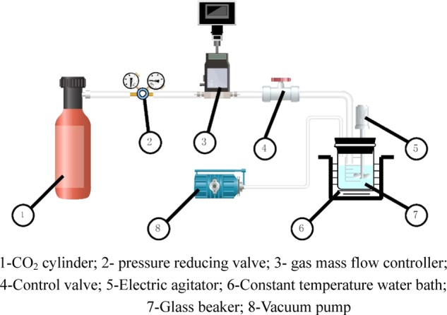
NP-stabilized CO2 foam generation system.
2.4. Measurement of Bulk Foam Static Properties and Error Analysis
Bulk foam static properties mainly consist of foam generation capacity and foam stability, which could be characterized through the foam height and foam decay half-life results, respectively.
2.4.1. Foam Height
When the rich and stable bulk foam was obtained, the maximum height of the generated foam was visually measured in the 1000 mL glass beaker as the column height between the top bubble surface and the liquid interface after pulling up the electric agitator from the NP–surfactant solution. For instance, the generated NP-stabilized foam in the glass beaker in Test No. 3, as listed in Table 2, is depicted in Figure 2, from which it is observed that the foam has been well generated and the foam height is measured to be 72 mm.
Table 2. Five-Factor Four-Level Parameter Combinations Based on OED.
| test no. | NP model | surfactant concentration Csurf (wt %) | NP concentration CNP (wt %) | temperature t (°C) | salinity Csalt (NaCl wt %) |
|---|---|---|---|---|---|
| 1 | NP150 | 0 | 0 | 25 | 0 |
| 2 | NP150 | 0.05 | 0.1 | 35 | 1 |
| 3 | NP150 | 0.1 | 0.15 | 45 | 2 |
| 4 | NP150 | 0.15 | 0.2 | 55 | 3 |
| 5 | NP200 | 0 | 0.1 | 45 | 3 |
| 6 | NP200 | 0.05 | 0 | 55 | 2 |
| 7 | NP200 | 0.1 | 0.2 | 25 | 1 |
| 8 | NP200 | 0.15 | 0.15 | 35 | 0 |
| 9 | NP300 | 0 | 0.15 | 55 | 1 |
| 10 | NP300 | 0.05 | 0.2 | 45 | 0 |
| 11 | NP300 | 0.1 | 0 | 35 | 3 |
| 12 | NP300 | 0.15 | 0.1 | 25 | 2 |
| 13 | NPOX50 | 0 | 0.2 | 35 | 2 |
| 14 | NPOX50 | 0.05 | 0.15 | 25 | 3 |
| 15 | NPOX50 | 0.1 | 0.1 | 55 | 0 |
| 16 | NPOX50 | 0.15 | 0 | 45 | 1 |
Figure 2.
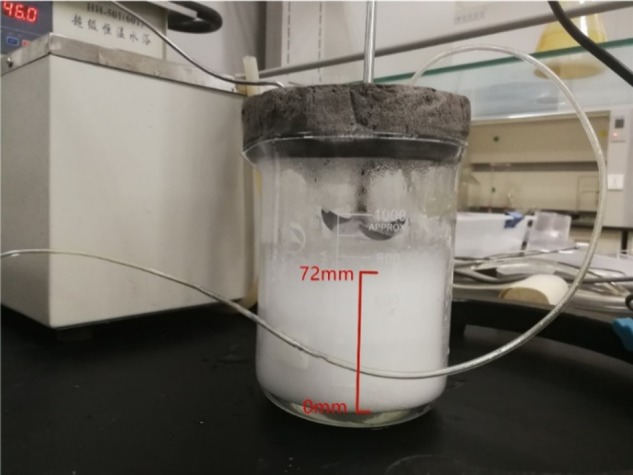
Well-generated foam with the foam height measurement result for Test No. 3.
2.4.2. Foam Decay Half-Life
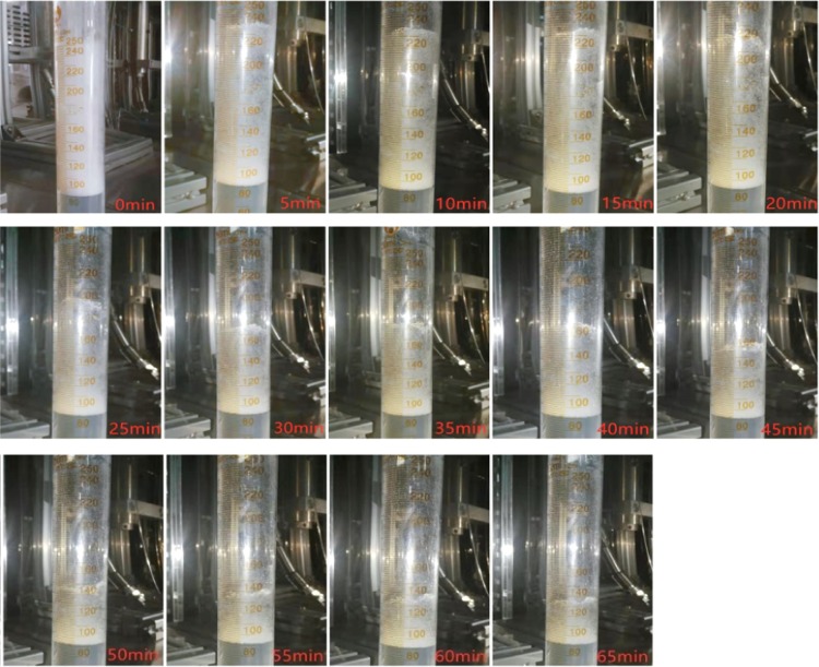
The foam half-life, the time taken to reach half of the foams’ original height, has been widely employed to characterize the foam stability with a larger value, indicating a more stable foam. After completing the measurement of the foam height in the beaker, the foam half-life is measured in a 250 mL graduated cylinder (37.7 mm in diameter and 213 mm in height). The generated foam together with the aqueous solution was poured into the cylinder from the glass beaker with a uniform speed until the bubble top surface reaches the largest scale of the glass container. The transfer of the generated foam to a much smaller but taller container could produce a much larger foam column reading data, which significantly reduces the measurement error of the foam volume variation with time. The foam half-time was measured as the time when the foam volume reduces to half of the initial volume value in the graduated cylinder. Figure 3 displays the measurement process of the foam half-life in Test No. 3. It could be clearly observed that the initial foam volume is 160 mL and, after 40 min, the volume decreases to 80 mL, which determines the foam half-life to be 40 min.
Figure 3.
Foam half-life measurement process and result for Test No. 3.
The measurement error could be analyzed based on the following characteristic values in the tests. As to the foam height, the visual measurement error is 2.0 mm, indicating a relative error of 10% based on the minimum value of 20 mm in all rounds of measurements. In a similar way, the foam half-life measurement error is estimated to be 7.5%, which consists of the volume measurement error of 6.7% (10 mL in 150 mL) plus 0.8% error on the time measurement (5 s in 10 min).
2.5. Experimental Parameter Arrangement Based on the OED
The static properties of NP-stabilized CO2 foam were investigated based on the orthogonal arrangement of the five influential factors, including NP size, surfactant concentration, NP concentration, temperature, and salinity. When each of the five parameters was studied at four levels, the number of experiments required for one-factor-at-a-time design could reach 1024 (=45), which is too large to be fulfilled in a limited time and at acceptable test expenses. In the orthogonal test design, however, the number for the five-factor four-level case could be significantly reduced to 16 according to an L16(45) orthogonal table, which obviously alleviates the workload compared to 1024 in the separate variable test scheme.
Among the five influential factors, the NP size is the first factor and is studied at four various diameter levels, 7, 12, 14, and 40 nm, based on the reported range of 12–36 nm.28,40,41 The surfactant concentration is the second influential factor and varies at four levels, 0, 0.05, 0.1, and 0.15 wt %, respectively, with reference to the reported research studies.28,40 As the NP concentration of 0.05–0.15 wt %40,42−45 has shown good performance in core flooding and foam static behaviors, the variation of the NP concentration as the third factor starts from 0 to 0.2 wt % at four levels, 0, 0.1, 0.15, and 0.2 wt %. The fourth influential factor is the system temperature and is studied at four levels, 25, 35, 45, and 55 °C, which covers most temperature ranges in reported research studies.28,43−47 Solution salinity is the fifth parameter and is investigated based on four different NaCl concentrations, 0, 1, 2, and 3 wt %, in the aqueous mixture in compliance with the reported range 0–3 wt %.43−47
Table 2 lists the 16 experimental parameter combinations based on the orthogonal arrangement principle with the help of the software “Orthogonality Experimental Assistant” (Sharetop Software Studio).
It is noted that the parameter of pressure, which could influence CO2 solubility and miscibility, is not included in the studying variable list. Actually, the pressure effect on the static properties of NP-stabilized CO2 foam was scarcely reported in the previous literature. Emrani et al.48 found a decrease in the half-life of nanosilica-stabilized CO2 foam as pressure increased from 300 to 800 psi, while they tested the foam generation capability with shake tests under ambient conditions. Both Xiao et al.49 and Kumar et al.50 carried out the static property studies on NP-stabilized CO2 foam under atmospheric conditions to help in understanding the supercritical CO2 foam displacement behaviors in harsh reservoir conditions. It is deduced that the difficulties in evaluating both the static properties of foam height and foam half-life in pressurized containers result in insufficient studies on the effect of pressure on NP-stabilized CO2 foam.23 In addition, the aim of our work is to demonstrate the feasibility of OED on optimal parameter screening instead of focusing on single-parameter investigations; therefore, we did not involve the parameter of pressure as one of the screening factors in this paper.
2.6. Evaluation of the Impact of Various Factors on Bulk Foam Static Properties
The impact of each factor on bulk foam static properties was evaluated based on the mean and range analysis through K and B values, which are the reference standard of the orthogonal test and are described as follows
| 1 |
| 2 |
where Si indicates the sum of the test results corresponding to the ith level number (i = 1, 4 in the five-factor four-level case) and s is the number of occurrences of each level in the factor column in the orthogonal table (s = 4 according to Table 2); therefore, Ki refers to the average results of the ith level in one specific factor, whereas the B value represents the difference between the maximum K value and the minimum K value of the specific factor, reflecting the significance of the studied factor on the foam static characteristics. Based on the K and B values, the effect and significance of each influential factor on the foam static behavior could be obtained, and thereby the reasonable parameter combinations could be proposed to achieve NP-stabilized foam with satisfactory foamability and stability properties.
3. Results and Discussion
3.1. Effect of Single Parameter on Foam Static Properties
3.1.1. Overview of the Foam Height and Foam Half-Life Results from the 16 Tests
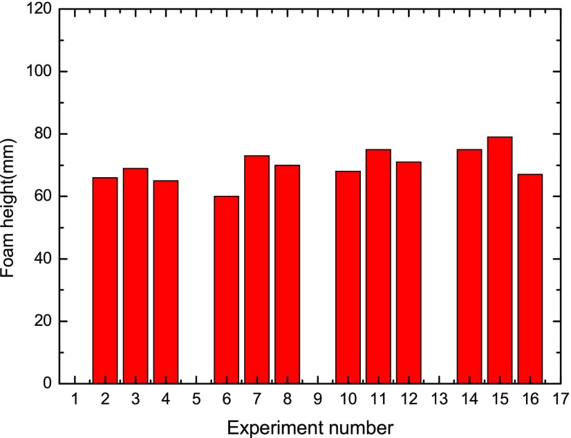
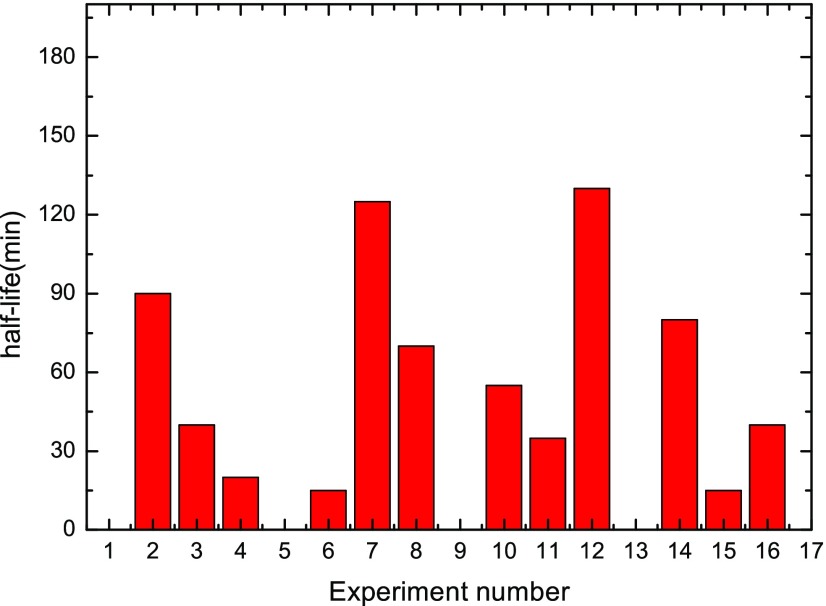
In correspondence to Table 2, Figures 4 and 5 display the foam height and foam half-life results under the 16 orthogonally distributed parameter conditions. As seen from Figure 4, a remarkable difference could be observed among various conditions, with foam height varying from 0 mm (the case of Nos. 1, 5, 9, and 13 in which there is no surfactant present) to 79 mm in case No. 15 under the parameters of Csurf = 0.1 wt %, CNP = 0.1 wt %, t = 55 °C, and Csalt = 0. Similarly, Figure 5 shows obvious scattering on foam half-time results ranging from 0 min (case of Nos. 1, 5, 9, and 13) to 130 min in the case of No. 12.
Figure 4.
Foam height results under the 16 orthogonally distributed parameter conditions.
Figure 5.
Foam half-life results under the 16 orthogonally distributed parameter conditions.
To gain insight into each factor’s effect and thereby to propose an optimal parameter combination, more detailed analysis has been carried out in the following subsections.
3.1.2. Effect of NP Size
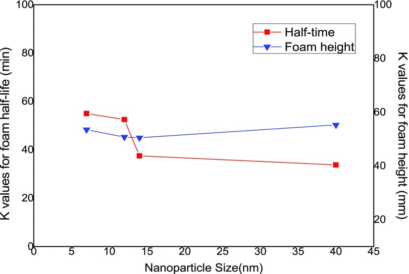
As shown in Table 1, four models of SiO2 NPs with different sizes of 40, 14, 12, and 7 nm were employed in the study. Figure 6 displays the K values of the foam half-life and foam height on the left and right sidebar, respectively, corresponding to the four different levels of NP sizes. As can be clearly seen from the figure, the NP with the smallest diameter of 7 nm and the highest specific area of 300 m2/g produces the longest foam half-life results, showing the best foam stability. The foam stability of the NP–surfactant solution decreases with increasing NP sizes, indicating that smaller NPs are more advantageous for generating CO2 foam with satisfactory static characteristics. It is also observed from the figure that when the particle size increases from 12 to 14 nm, the foam half-life value decreases obviously from 53 to 38 min. On the other hand, the size impact on the foam height result is not significant in the studied NP size range 7–40 nm.
Figure 6.
Effect of NP size on the foam half-life and foam height results.
The increasing foam stability with decreasing NP sizes could attribute to the easy movement of the smaller NPs to the gas–liquid interface of the foam.51,52 Higher energy barrier between the particles and the interface is seen for NPs with larger diameters. Hence, smaller NPs migrate faster into the interface and better improved foam stability is observed than in the larger-sized NPs.53 The experimental results on the foam height are to some extent consistent with Xiao et al.,49 who found that the foamability could be promoted by either smaller or larger size NPs at different foam qualities.
3.1.3. Effect of Surfactant Concentration
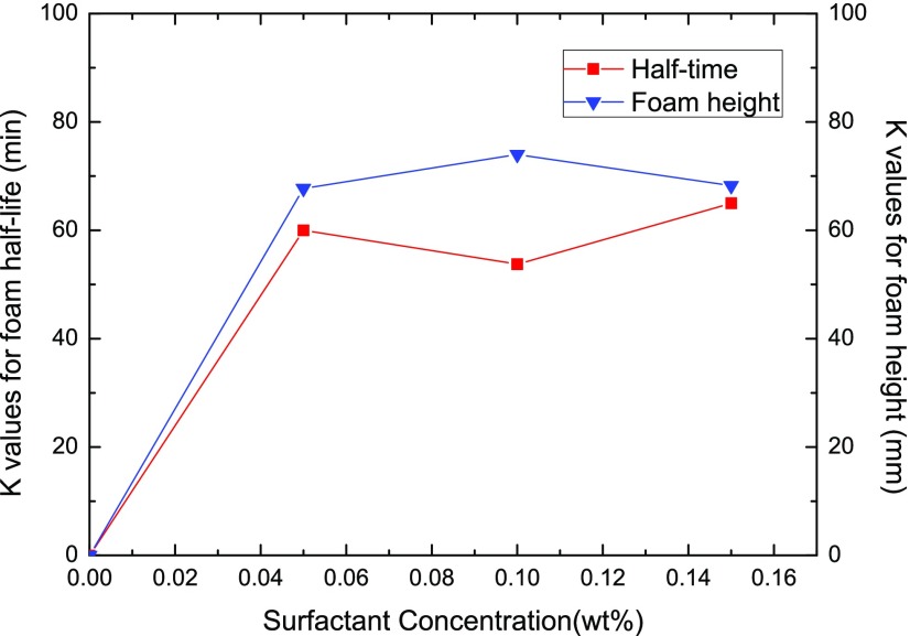
Four levels of surfactant concentrations of 0, 0.05, 0.1, and 0.15 wt % have been employed in the tests, and their average effects on foam static behavior are plotted in Figure 7 in terms of the foam half-life and foam height results. A remarkable effect of surfactant concentration, especially in the region of 0–0.05 wt %, could be observed in this figure, indicating that the presence of the surfactant is essential for the NP-stabilized CO2 foam capacity and stability. Although further increased surfactant concentration could result in better static characteristics; for instance, the CO2 foam at the highest Csurf of 0.15 wt % shows the longest half-life of 65 min and the Csurf of 0.1 wt % shows the highest foam height of 74 mm, its effects become insignificant in the Csurf region of 0.05–0.15 wt % compared to the impact in the region of 0–0.05 wt %. According to Emrani et al.,54 the critical micelle concentration (CMC) of AOS in CO2 foam is around 0.1 wt %, and the presence of NP does not show obvious influence on the CMC of the surfactant. Our results show that even 0.05 wt % AOS could generate satisfactory CO2 foam in the presence of NP, while 0.15 wt % AOS could achieve the best static behavior NP foams, indicating that the AOS concentration just above CMC could generate satisfactory foams even at high salinity and in the presence of oil in the environment, validating again the positive function of NP on CO2 foam generation and stability.
Figure 7.
Effect of surfactant concentration on the foam half-life and foam height results.
The reason for the presence of the surfactant on significantly enhancing the foam generation and stability could be attributed to the increased hydrophobicity by the surfactant adsorption at the particle–water interface due to the electrostatic interaction between the surface of the nanoparticles and the oppositely charged surfactant head groups. In addition, the available surface free energy for the attachment of NPs to the interface of the foam can be regulated by changing the surfactant concentration.23 Actually, mixing of the surfactant and hydrophilic NPs is less technical and cheaper than surface modification of NPs through chemical treatment since hydrophilic NPs are less expensive and readily disperse in water.55
3.1.4. Effect of NP Concentration
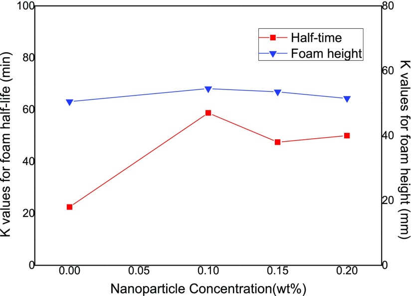
The effects of NP concentration on the foam half-life and foam height values are displayed in Figure 8 through averaging the results obtained at four different levels of 0, 0.1, 0.15, and 0.2 wt %, respectively. Based on the foam half-life results with reference to the left sidebar, it is observed that an intermediate concentration of 0.1 wt % NPs produces the most stable foam with the longest half-time of 58.8 min in contrast with 20, 47.5, and 50 min at 0, 0.15, and 0.2 wt %, respectively. According to the K value on the right side of the diagram, the foam height is between 50 and 55 mm in all of the studied NP concentration range, indicating that the NP concentration has little effect on CO2 foam generation capacity.
Figure 8.
Effect of NP concentration on the foam half-life and foam height results.
Although the presence of NPs slows down liquid drainage and film thinning, the accumulation of NPs at the air–water interface of the foam has to exceed a certain threshold concentration to enhance foam stability. At a low concentration of NPs, the adsorbed nanoparticles at the gas–liquid interface are not sufficient to improve the foam stability, thereby a certain NP concentration is needed to generate stable foam.23 Our experimental observations are consistent with Yekeen et al.,27 who reported an optimal NP concentration for CO2 foam half-life results and a negligible effect of NP concentration on foam height properties.
3.1.5. Effect of Temperature
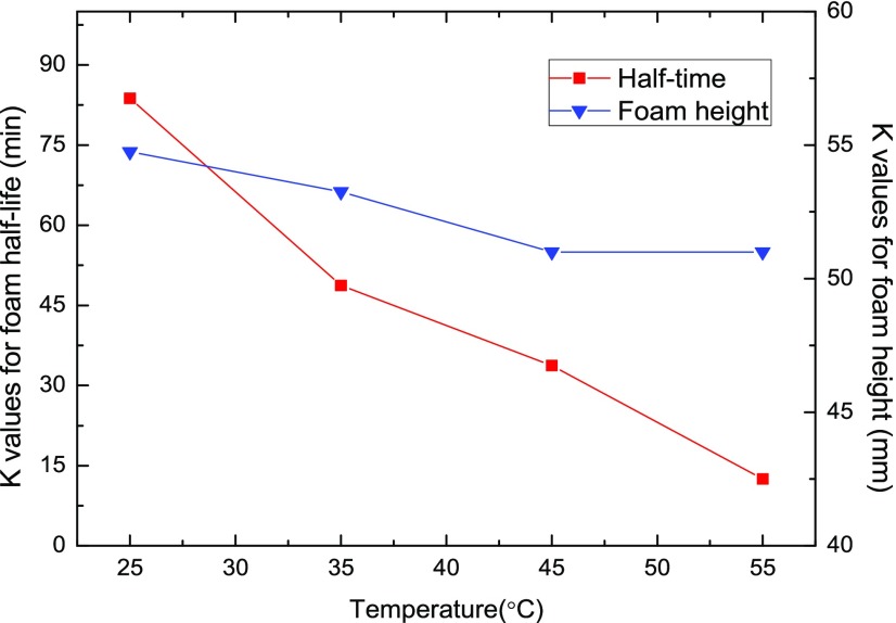
The significant impact of temperature on foam stability behavior is observed from Figure 9, in which the K values of the foam half-life and foam height results are depicted under various temperatures. The foam half-life results, as plotted in squares with reference to the left sidebar scales, decrease unanimously from 83.75 min at 25 °C to 12.5 min at 55 °C, indicating that an elevated system temperature is unfavorable to the NP-stabilized foam stability. The temperature effect on foam generation capacity, however, is not as significant as that on foam stability, with foam height values varying between 51 and 54.75 mm in the studied temperature range of 25–55 °C.
Figure 9.
Effect of temperature on the foam half-life and foam height results.
This accelerated foam rupture process under increased temperature conditions could contribute to the insufficient adsorption of NPs on the foam lamellae due to the more intense thermal agitation of NPs at higher temperatures, which leads to a reduction in the foaming solution viscosity and the increasing rate of gas diffusion and liquid drainage from the foam films.23
3.1.6. Effect of Solution Salinity
Electrolyte concentration is a major concern for the generation and stability of NP foams. Therefore, in this section, the relationship between the NP-stabilized foam half-life and height and the NaCl concentration in the aqueous solution is investigated.
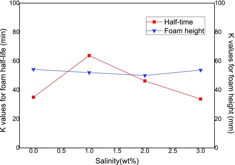
As shown in Figure 10, the foam height is stable between 50 and 54.3 mm in the solution salinity range of 0–3.0 wt %. The experimental observation is consistent with Yu et al.,56 who reported that there was no significant influence of salinity on CO2 foam generation. However, the foam demonstrates the highest stability with a half-life of 63.8 min at a salinity of 1 wt %, clearly in contrast with 35, 46.3, and 33.8 min at a salinity of 0, 2.0, and 3.0 wt %, respectively. The observation of optimal, or critical, salt concentration on foam stability has also been reported in previous studies,57,58 and the mechanism behind this phenomena has been attributed to the competitive action between the repulsive electrostatic forces and the van der Waals forces according to Derjaguin–Landau–Verwey–Overbeek (DLVO) theory.52
Figure 10.
Effect of salinity on the foam half-life and foam height results.
3.2. Range Analysis of the Five Influencing Factors
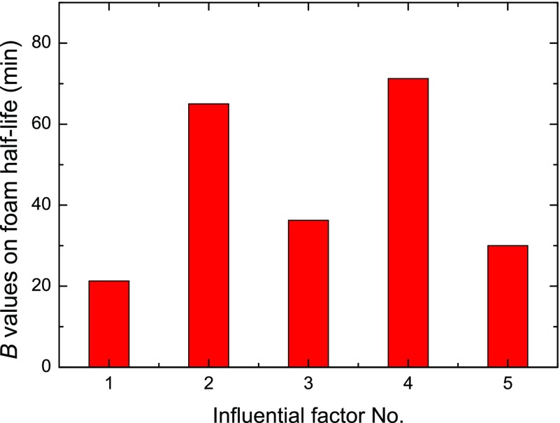
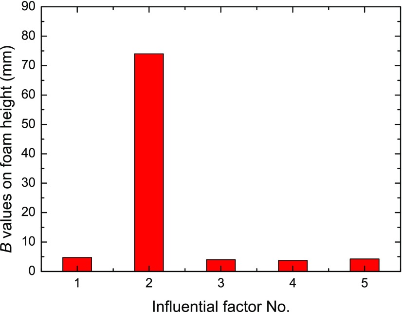
The affecting ranges for each studied factors on the foam half-life and foam height properties are investigated through the B parameter as described in eq 2 and are block mapped in Figures 11 and 12, respectively. With influential factor No. 1–5 corresponding to NP size, surfactant concentration, NP concentration, temperature, and salinity, the importance of each factor on foam static characteristics could be clearly observed.
Figure 11.
B values of various influential factors on the foam half-life result (factor Nos. 1–5 represent NP size, surfactant concentration, NP concentration, temperature, and salinity).
Figure 12.
B values of various influential factors on the foam height result (factor Nos. 1–5 represent NP size, surfactant concentration, NP concentration, temperature, and salinity).
As shown in Figure 11, the most determinative factor for a longer foam half-time is factor No. 4 of temperature, followed by the surfactant concentration, NP concentration, NP size, and salinity, whereas Figure 12 shows that the most significant influential factor for foam height is the surfactant concentration, which shows obvious dominance on foam generation capacity compared to other four factors of salinity, temperature, NP size, and NP concentration.
3.3. Optimal Parameters Based on the Results of Orthogonally Designed Experiments
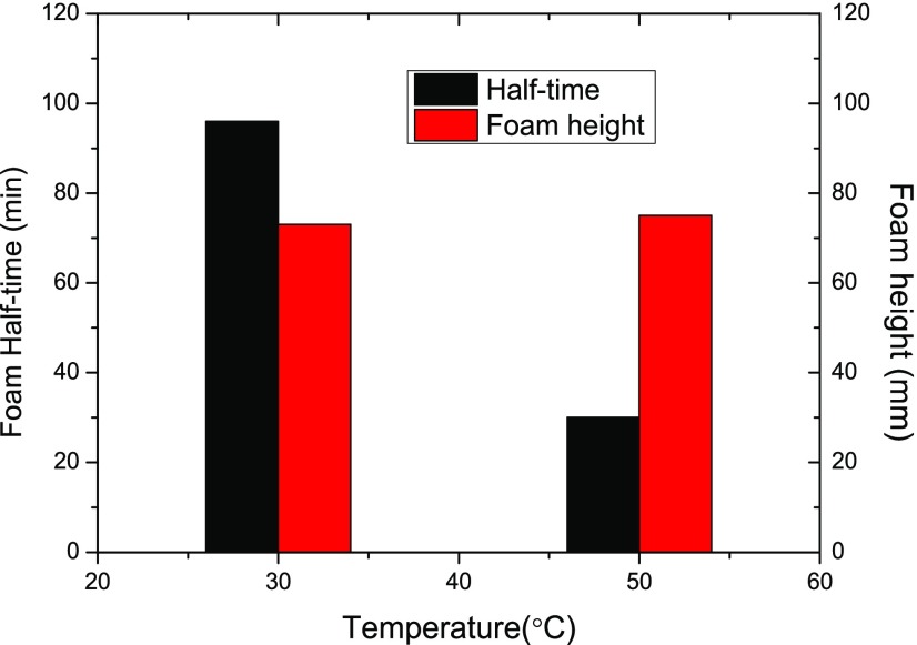
Based on the above analysis of each factor’s influence on foam static characteristics, we could propose the optimal combination of parameters to generate NP-stabilized CO2 foam with the most favorable properties in the test range. In practical conditions where the reservoir fluid salinity and temperature are usually fixed, the optimal parameter combination of surfactant concentration, NP concentration, and NP size is the main concern of engineers. Based on the results obtained from Figures 6–8, a combinative parameter of 0.15 wt % AOS + 0.1 wt % NP300 (7 nm in primary size) was employed with an aim to generate NP-stabilized CO2 foam with satisfactory static properties under a given salinity of 1 wt % and temperatures of 30 and 50 °C in the presence of oil.
Figure 13 shows the foam half-life and foam height results of the NP-stabilized CO2 foam under the proposed parameters. It is clearly observed that the foam could remain stable at the half decay times of 30 and 96 min and the generated foam height could reach 73 and 75 mm, respectively, at 30 and 50 °C, which are among the best behaviors in the test ranges. It is concluded, therefore, that the OED method could be properly employed in multifactor multilevel investigations on foam static properties, which could further help essentially in the screening process of the NP-stabilized CO2 foam for its successful field applications.
Figure 13.
Foam half-life and foam height results under optimal parameter combination (0.15 wt % AOS + 0.1 wt % NP300) supplied from OED tests.
4. Conclusions
In this paper, parameter screening studies have been carried out to achieve satisfactory static behavior of NP-stabilized CO2 foam in the presence of oil. The effects of five key factors, including NP size, surfactant concentration, NP concentration, temperature, and salinity, have been investigated at four different levels based on the OED method. With orthogonally arranged parameters, 16 tests were performed to analyze the effect of various factors on foam static characteristics of the foam height and foam half-life. The following concluding remarks have been obtained:
-
(1)
In the test ranges of NP size of 7–40 nm and surfactant concentration of 0–0.15 wt %, smaller NP size and higher surfactant concentration lead to better foam stability.
-
(2)
In the test NP concentration range of 0–0.2 wt %, an intermediate value of 0.1 wt % could stabilize the CO2 foam with the longest period of time.
-
(3)
In the test ranges of temperature between 25 and 55 °C and NaCl concentration between 0 and 3 wt %, a critical salinity of 1 wt % was observed for better foam stability.
-
(4)
Compared to the other four factors, range analysis indicates that temperature is the most dominating factor on the NP-stabilized CO2 foam half-life, while the surfactant concentration is the dominating factor influencing the foam generation capacity.
-
(5)
Satisfactory foam static characteristics were obtained based on the OED-recommended parameter combination of 0.15 wt % AOS, 0.1 wt % NP, and NP300 (7 nm) under two system temperatures of 30 and 50 °C, validating the robustness of the OED method on parameter screening for optimizing the static properties of NP-stabilized CO2 foam.
Acknowledgments
The authors would like to thank financial support from the National Natural Science Foundation of China (NSFC No. 51476081).
The authors declare no competing financial interest.
References
- Gaspar A. T. F. S.; Suslick S. B.; Ferreira D. F.; Lima G. A. C. In Enhanced Oil Recovery With CO2 Sequestration: A Feasibility Study of A Brazilian Mature Oil Field, SPE 94939, SPE/EPA/DOE Exploration and Production Environmental Conference, Texas, 2005.
- Godeca M.; Kuuskraaa V.; Van Leeuwen T.; Melzer L. S.; Wildgust N. CO2 storage in depleted oil fields: The worldwide potential for carbon dioxide enhanced oil recovery. Energy Procedia 2011, 4, 2162–2169. 10.1016/j.egypro.2011.02.102. [DOI] [Google Scholar]
- Ettehadtavakkol A.; Lake L. W.; Byrant S. L. CO2-EOR and storage design optimization. Int. J. Greenhouse Gas Control 2014, 25, 79–92. 10.1016/j.ijggc.2014.04.006. [DOI] [Google Scholar]
- Welkenhuysen K.; Rupert J.; Compernolle T.; Ramirez A.; Swennen R.; Piessens K. Considering economic and geological uncertainty in the simulation of realistic investment decisions for CO2-EOR projects in the North Sea. Appl. Energy 2017, 185, 745–761. 10.1016/j.apenergy.2016.10.105. [DOI] [Google Scholar]
- Holm L. W. Evolution of the Carbon-Dioxide Flooding Processes. J. Pet. Technol. 1987, 39, 1337–1342. 10.2118/17134-PA. [DOI] [Google Scholar]
- Smith D. H.Promise and Problems of Miscible-Flood Enhanced Oil Recovery: The Need for Surfactant-Based Sweep and Mobility Control. In Surfactant Based Mobility Control Progress in Miscible-Flood Enhanced Oil Recovery;Smith D. H., Ed.; ACS Symposium Series 373; American Chemical Society: Washington, DC, 1988; pp 2–37. [Google Scholar]
- Lee H. O.; Heller J. P. Laboratory measurements of CO2 foam mobility. SPE Reservoir Eng. 1990, 5, 193–197. 10.2118/17363-PA. [DOI] [Google Scholar]
- CO2 foam floods: foam properties and mobility- reduction effectiveness. J. Pet. Technol. 1998, 50, 69–70. 10.2118/0198-0069-JPT. [DOI] [Google Scholar]
- Li R. F.; Yan W.; Liu S.; Hirasaki G.; Miller C. A. Foam mobility control for surfactant enhanced oil recovery. SPE J. 2010, 15, 928–942. 10.2118/113910-PA. [DOI] [Google Scholar]
- Talebian S. H.; Masoudi R.; Tan I. M.; Zitha P. L. J. Foam assisted CO2-EOR: a review of concept, challenges, and future prospects. J. Pet. Sci. Eng. 2014, 120, 202–215. 10.1016/j.petrol.2014.05.013. [DOI] [Google Scholar]
- Turta A. T.; Singhal A. K. Field foam applications in enhanced oil recovery projects: screening and design aspects. J. Can. Pet. Technol. 2002, 41, 577. 10.2118/02-10-14. [DOI] [Google Scholar]
- Osei-Bonsu K.; Shokri N.; Grassia P. Foam stability in the presence and absence of hydrocarbons: from bubble- to bulk-scale. Colloids Surf., A 2015, 481, 514–526. 10.1016/j.colsurfa.2015.06.023. [DOI] [Google Scholar]
- Hunter N.; Pugh R. J.; Franks G. V.; Jameson G. J. The role of particles in stabilising foams and emulsions. Adv. Colloid Interface Sci. 2008, 137, 57–81. 10.1016/j.cis.2007.07.007. [DOI] [PubMed] [Google Scholar]
- Yu J.; Khalil M.; Liu N.; Lee R. Effect of particle hydrophobicity on CO2 foam generation and foam flow behavior in porous media. Fuel 2014, 126, 104–108. 10.1016/j.fuel.2014.02.053. [DOI] [Google Scholar]
- Zhao G.; Dai C.; Zhang Y.; Chen A.; Yan Z.; Zhao M. Enhanced foam stability by adding comb polymer gel for in-depth profile control in high temperature reservoirs. Colloids Surf., A 2015, 482, 115–124. 10.1016/j.colsurfa.2015.04.041. [DOI] [Google Scholar]
- Maestro A.; Rio E.; Drenckhan W.; Langevin D.; Salonen A. Foams stabilised by mixtures of nanoparticles and oppositely charged surfactants: relationship between bubble shrinkage and foam coarsening. Soft Matter 2014, 10, 6975–6983. 10.1039/C4SM00047A. [DOI] [PubMed] [Google Scholar]
- Ko S.; Huh C. Use of nanoparticles for oil production applications. J. Pet. Sci. Eng. 2019, 172, 97–114. 10.1016/j.petrol.2018.09.051. [DOI] [Google Scholar]
- Du D. X.; Zhang X.; Li Y. G.; Zhao D.; Wang F.; Sun Z. F. Experimental Study on Rheological Properties of Nanoparticle-stabilized Carbon Dioxide Foam. J. Nat. Gas Sci. Eng. 2020, 75, 103140 10.1016/j.jngse.2019.103140. [DOI] [Google Scholar]
- Kam S. I.; Rossen W. R. Anomalous capillary pressure, stress, and stability of solids-coated bubbles. J. Colloid Interface Sci. 1999, 213, 329–339. 10.1006/jcis.1999.6107. [DOI] [PubMed] [Google Scholar]
- Shrestha L. K.; Acharya D. P.; Sharma S. C.; Aramaki K.; Asaoka H.; Ihara K.; Tsunehiro T.; Kunieda H. Aqueous foam stabilized by dispersed surfactant solid and lamellar liquid crystalline phase. J. Colloid Interface Sci. 2006, 301, 274–281. 10.1016/j.jcis.2006.04.065. [DOI] [PubMed] [Google Scholar]
- Karakashev S. I.; Ozdemir O.; Hampton M. A.; Nguyen A. V. Formation and stability of foams stabilized by fine particles with similar size, contact angle and different shapes. Colloids Surf., A 2011, 382, 132–138. 10.1016/j.colsurfa.2010.09.023. [DOI] [Google Scholar]
- Farhadi H.; Riahi S.; Ayatollahi S.; Ahmadi H. Experimental study of nanoparticle–surfactant -stabilized CO2 foam: Stability and mobility control. Chem. Eng. Res. Des. 2016, 111, 449–460. 10.1016/j.cherd.2016.05.024. [DOI] [Google Scholar]
- Yekeen N.; Manan M. A.; Idris A. K.; Padmanabhan E.; Junin R.; Samin A. M.; Gbadamosi A. O.; Oguamah I. A comprehensive review of experimental studies of nanoparticles-stabilized foam for enhanced oil recovery. J. Pet. Sci. Eng. 2018, 164, 43–74. 10.1016/j.petrol.2018.01.035. [DOI] [Google Scholar]
- Attarhamed F.; Zoveidavianpoor M.; Jalilavi M. The incorporation of silica nanoparticle and alpha olefin sulphonate in aqueous CO2 foam: investigation of foaming behavior and synergistic effect. Pet. Sci. Technol. 2014, 32, 2549–2558. 10.1080/10916466.2013.845575. [DOI] [Google Scholar]
- Worthen A. J.; Bagaria H. G.; Chen Y. S.; Bryant S. L.; Huh C.; Johnson K. P. Nanoparticle-stabilized carbon dioxide-in-water foams with fine texture. J. Colloid Interface Sci. 2013, 391, 142–151. 10.1016/j.jcis.2012.09.043. [DOI] [PubMed] [Google Scholar]
- Babamahmoudi S.; Riahi S. Application of nano particle for enhancement of foam stability in the presence of crude oil: Experimental investigation. J. Mol. Liq. 2018, 264, 499–509. 10.1016/j.molliq.2018.04.093. [DOI] [Google Scholar]
- Yekeen N.; Idris A. K.; Manan M. A.; Samin A. M.; Risal A. R.; Kun T. X. Bulk and bubble-scale experimental studies of influence of nanoparticles on foam stability. Chin. J. Chem. Eng. 2017, 25, 347–357. 10.1016/j.cjche.2016.08.012. [DOI] [Google Scholar]
- Singh R.; Mohanty K. K. Study of Nanoparticle-Stabilized Foams in Harsh Reservoir Conditions. Transp. Porous Media 2020, 131, 135–155. 10.1007/s11242-018-1215-y. [DOI] [Google Scholar]
- Antony J. Taguchi or classical design of experiments: a perspective from a practitioner. Sens. Rev. 2006, 26, 227–230. 10.1108/02602280610675519. [DOI] [Google Scholar]
- Ji L. J.; Si Y. F.; Liu H. F.; Song X. L.; Zhu W.; Zhu A. P. Application of orthogonal experimental design in synthesis of mesoporous bioactive glass. Microporous Mesoporous Mater. 2014, 184, 122–126. 10.1016/j.micromeso.2013.10.007. [DOI] [Google Scholar]
- Shan W.; Wu L.; Tao N.; Chen Y.; Guo D. Optimization method for green SrAl2O4: Eu2+, Dy3+ phosphors synthesized via co-precipitation route assisted by microwave irradiation using orthogonal experimental design. Ceram. Int. 2015, 41, 15034–15040. 10.1016/j.ceramint.2015.08.050. [DOI] [Google Scholar]
- Su L.; Zhang J.; Wang C.; Zhang Y.; Li Z.; Song Y.; Jin T.; Ma Z. Identifying main factors of capacity fading in lithium ion cells using orthogonal design of experiments. Appl. Energy 2016, 163, 201–210. 10.1016/j.apenergy.2015.11.014. [DOI] [Google Scholar]
- Zuo W.; E J.; Liu X.; Peng Q.; Deng Y.; Zhu H. Orthogonal Experimental Design and Fuzzy Grey Relational Analysis for emitter efficiency of the micro-cylindrical combustor with a step. Appl. Therm. Eng. 2016, 103, 945–951. 10.1016/j.applthermaleng.2016.04.148. [DOI] [Google Scholar]
- Ma S.; Wang H.; Wang Y.; Bu H.; Bai J. Bio-hydrogen production from cornstalk wastes by orthogonal design method. Renewable Energy 2011, 36, 709–713. 10.1016/j.renene.2010.08.019. [DOI] [Google Scholar]
- Zhu J.; Chew D. A. S.; Lv S.; Wu W. Optimization method for building envelope design to minimize carbon emissions of building operational energy consumption using orthogonal experimental design (OED). Habitat Int. 2013, 37, 148–154. 10.1016/j.habitatint.2011.12.006. [DOI] [Google Scholar]
- Farajzadeh R.; Krastev R.; Zitha P. L. J. Foam films stabilized with alpha olefin sulfonate (AOS). Colloids Surf., A 2008, 324, 35–40. 10.1016/j.colsurfa.2008.03.024. [DOI] [PubMed] [Google Scholar]
- Du D. X.; Li Y. G.; Zhang D.; Dong X.; Wang F.; Chao K. Experimental study on the inlet behavior of CO2 foam three phase displacement processes in porous media. Exp. Therm. Fluid Sci. 2019, 103, 247–261. 10.1016/j.expthermflusci.2019.01.018. [DOI] [Google Scholar]
- Qi Q.Optimization of nanoparticle composite foam flooding system and study on its oil displacement performance. Master Thesis, Qingdao University of Science and Technology, 2018. [Google Scholar]
- Bayata A. E.; Rajaei K.; Junin R. Assessing the Effects of Nanoparticle Type and Concentration on the Stability of CO2 foams and the Performance in Enhanced Oil Recovery. Colloids Surf., A 2016, 511, 222–231. 10.1016/j.colsurfa.2016.09.083. [DOI] [Google Scholar]
- Singh R.; Mohanty K. K. Synergy between Nanoparticles and Surfactants in Stabilizing Foams for Oil Recovery. Energy Fuels 2015, 29, 467–479. 10.1021/ef5015007. [DOI] [Google Scholar]
- Singh R.; Mohanty K. K. Foam flow in a layered, heterogeneous porous medium: A visualization study. Fuel 2017, 197, 58–69. 10.1016/j.fuel.2017.02.019. [DOI] [Google Scholar]
- Zhang K.; Li Y.; Hong A.; Wu K.; Jing G.; Torsæter O.; Chen S.; Chen Z. In Nanofluid Alternating Gas for Tight Oil Exploitation, SPE 176241, SPE/IATMI Asia Pacific Oil & Gas Conference and Exhibition held in Bali, Indonesia, 2015.
- Rognmo A. U.; Heldal S.; Fernø M. A. Silica nanoparticles to stabilize CO2-foam for improved CO2 utilization: Enhanced CO2 storage and oil recovery from mature oil. Fuel 2018, 216, 621–626. 10.1016/j.fuel.2017.11.144. [DOI] [Google Scholar]
- Emrani A. S.; Nasr-El-Din H. A. An experimental study of nanoparticle-polymer-stabilized CO2 foam. Colloids Surf., A 2017, 524, 17–27. 10.1016/j.colsurfa.2017.04.023. [DOI] [Google Scholar]
- Rognmo A. U.; Horjen H.; Fernø M. A. Nanotechnology for improved CO2 utilization in CCS: Laboratory study of CO2-foam flow and silica nanoparticle retention in porous media. Int. J. Greenhouse Gas Control 2017, 64, 113–118. 10.1016/j.ijggc.2017.07.010. [DOI] [Google Scholar]
- AlYousef Z. A.; Almobarky M. A.; Schechter D. S. The effect of nanoparticle aggregation on surfactant foam stability. J. Colloid Interface Sci. 2018, 511, 365–373. 10.1016/j.jcis.2017.09.051. [DOI] [PubMed] [Google Scholar]
- Rahmani O. Mobility control in carbon dioxide-enhanced oil recovery process using nanoparticle-stabilized foam for carbonate reservoirs. Colloids Surf., A 2018, 550, 245–255. 10.1016/j.colsurfa.2018.04.050. [DOI] [Google Scholar]
- Emrani A. S.; Nasr-El-Din H. A. Stabilizing CO2 Foam by Use of Nanoparticles. SPE J. 2017, 22, 494–504. 10.2118/174254-PA. [DOI] [Google Scholar]
- Xiao C.; Balasubramanian S. N.; Clapp L. W. In Rheology of Supercritical CO2 Foam Stabilized by Nanoparticles, SPE-179621-MS, Proceedings of the SPE Improved Oil Recovery Conference, Tulsa, Oklahoma, April 11–13, 2016.
- Kumar S.; Mandal A. Investigation on stabilization of CO2 foam by ionic and nonionic surfactants in presence of different additives for application in enhanced oil recovery. Appl. Surf. Sci. 2017, 420, 9–20. 10.1016/j.apsusc.2017.05.126. [DOI] [Google Scholar]
- Kim I.; Worthen A. J.; Johnston K. P.; Dicarlo D. A.; Huh C. Size-dependent properties of silica nanoparticles for pickering stabilization of emulsions and foams. J. Nanopart. Res. 2016, 18, 82 10.1007/s11051-016-3395-0. [DOI] [Google Scholar]
- Yang W.; Wang T.; Fan Z.; Miao Q.; Deng Z.; Zhu Y. Foams stabilized by in situ-modified nanoparticles and anionic surfactants for enhanced oil recovery. Energy Fuels 2017, 31, 4721–4730. 10.1021/acs.energyfuels.6b03217. [DOI] [Google Scholar]
- Deleurence R.; Parneix C.; Monteux C. Mixtures of latex particles and the surfactant of opposite charge used as interface stabilizers–influence of particle contact angle, zeta potential, flocculation and shear energy. Soft Matter 2014, 10, 7088–7095. 10.1039/C4SM00237G. [DOI] [PubMed] [Google Scholar]
- Emrani A. S.; Nasr-El-Din H. A. In Stabilizing CO2-Foam Using Nanoparticles, SPE-174254-MS, SPE European Formation Damage Conference and Exhibition, Budapest, Hungary, June 3–5, 2015.
- Li S.; Qiao C.; Li Z.; Wanambwa S. Properties of carbon dioxide foam stabilized by hydrophilic nanoparticles and hexadecyltrimethylammonium bromide. Energy Fuels 2017, 31, 1478–1488. 10.1021/acs.energyfuels.6b03130. [DOI] [Google Scholar]
- Yu J.; An C.; Mo D.; Liu N.; Lee R. L. In Study of Adsorption and Transportation Behavior of Nanoparticles in Three Different Porous Media, Proceedings of SPE-153337-MS Improved Oil Recovery Symposium, Tulsa, Oklahoma, April 14–18, 2012.
- Yekeen N.; Manan M. A.; Idris A. K.; Samin A. M.; Risal A. R. Experimental investigation of minimization in surfactant adsorption and improvement in surfactant-foam stability in presence of silicon dioxide and aluminum oxide nanoparticles. J. Pet. Sci. Eng. 2017, 159, 115–134. 10.1016/j.petrol.2017.09.021. [DOI] [Google Scholar]
- Firouzi M.; Howes T.; Nguyen A. V. A quantitative review of the transition salt concentration for inhibiting bubble coalescence. Adv. Colloid Interface Sci. 2015, 222, 305–318. 10.1016/j.cis.2014.07.005. [DOI] [PubMed] [Google Scholar]


