

Abstract
This finite element (FE) study of lumbar biomechanics aims to predict how the parameters like range of motion (ROM), intervertebral disc pressure (IDP), cage stress and screw stress are affected by different direction-changeable cage positions. Firstly, the three-dimensional FE model of L3-L5 segment was developed, and the model was adjusted to adapt different direction-changeable cage positions at the L4-L5 level though transforaminal lumbar interbody fusion (TLIF) with pedicle screws. The effects of Type A (the lateral region), Type B (the lateralcentral region) and Type C (the anteriocentral region) on ROM, IDP, cage stress and screw stress were examined. The results showed that after implantation of interbody cages at different positions, the ROM at surgical level L4-L5 decreased substantially in all motion modes. The maximal stress in cage decreased with Type A, B and C in all motion modes except flexion and extension. The maximal cage stress was observed in Type A with 720.5 MPa in left rotation, in Type B with 707 MPa in flexion, in Type C with 397.3 MPa in left rotation, respectively. The maximal IDP was similar in three types, with 1.6 MPa in left lateral bending in Type A, 1.5 MPa in flexion in Type B, and 1.4 MPa in flexion in Type C. The range of screw peak stress was 16.4 to 61.1 MPa in Type A, 15.9 to 50.9 MPa in Type B, and 14.6 to 46.1 MPa Type C. In conclusion, comparing the cages with different positions, anteriocentral position cage has more advantages like lower cage stress, ODL and screw stress.
Keywords: Direction-changeable cage, finite element, biomechanics, TLIF
Introduction
Transforaminal lumbar interbody fusion (TLIF) was introduced in 1980s and has become a mainstream method to treat degenerative lumbar disorders since then. It has a number of advantages, including less invasiveness, less blood loss, less nerve root retraction and a shorter hospital stay compared with other lumbar fusion techniques [1-4]. A suitable interbody cage plays a pivotal role in successful bone fusion for TLIF. The materials of the interbody cage are constantly updated, from the early titanium metal and carbon fibers to polyetheretherketone (PEEK) materials now. And the morphology is also changing, from the early cylindrical metal threads to vertical annular titanium meshes, and from bullet shape to the anatomical kidney shape used today [5].
The kidney-shape PEEK cage has become popular in lumbar fusion as the biomechanics and clinical outcomes show that it has more merits compared to the traditional bullet-shape lumbar cage [5-8]. It has higher bone fusion rate, lower radiation exposure and fewer postoperative complications compared to the traditional bullet cage [5,6]. With its wide application, complications such as cage subsidence, migration and other problems have been emerged and not thoroughly solved yet. As the cage position could contribute to cage subsidence and migration in the traditional bullet-shape lumbar cage [9-11], while spine surgeons often choose the position for implantation according to their own experience. In terms of the direction-changeable kidney-shape cage, the optimal position remains controversial.
The finite element (FE) method is an ideal tool to study the biomechanics of spine, the strength of the FE method is that it enables calculating the internal stress on both the bone and the implants compared with cadaveric study under loading [12,13]. In this situation, we developed a FE lumbar spine model and aimed to predict how the parameters like the range of motion (ROM), intervetebral disc pressure (IDP), cage stress and screw stress were affected by different cage positions, and to provide a biomechanics reference for surgeons to choose the position for implantation.
Materials and methods
Development of FE L3-L5 spine model
The model was based on computed tomographic images with an interval of 0.625 mm of a healthy subject (male, 28 years old, 65 Kg, 175 cm). The images were imported into Mimics V14.0 software (Materialise, Ltd., Belgium) (Figure 1). After segmentation, 3D graphic data format files (Stereolithography, STL) were imported to Geomagic Studio V2013 software (3D Systems, Ltd., USA) to acquire nonuniform rational B-splines surfaces. The errors and regional burrs of the imported data were corrected, and cortical and cancellous bones were reconstructed individually to achieve accurate anatomical modeling. Output data were universal graphic data format files (Initial Graphics Exchange, IGS) and they were imported to the design modeler module of ANSYS V14.0 software (ANSYS, Ltd., USA) to build spine components.
Figure 1.
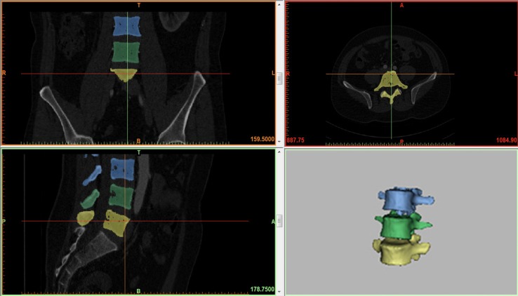
Model of the intact lumbar spine reconstructed by MIMICS 14.0.
The vertebral body was divided into three parts: cortical bone, cancellous bone, and posterior bone. The intervertebral disc was divided into nucleus pulposus and annulus ground. The intact model included 7 kinds of ligaments: anterior longitudinal ligament (ALL), posterior longitudinal ligament (PLL), ligament flava (LF), interspinal ligament (ISL), supraspinal ligament (SSL), intertransverse ligament (ITL), and capsular ligament (CL). The thickness of cortical bone was 1.0 mm, and the thickness of bone endplate was 0.5 mm. All kinds of ligaments were modeled as truss elements (T3D2), which had the property of tension-only [14]. The material properties of the model were assumed to be homogeneous and isotropic and were chosen from previous studies [14,15] (Table 1). The 3D tetrahedral elements were employed to mesh the FE model except for the ligaments. 184,522 nodes and 730,021 elements were contained in the intact FE model, which could effectively eliminate the influence of meshingon the accuracy of the calculation.
Table 1.
Material Properties Used in the Present Finite-Element Model of the Lumbar Spine
| Material properties | Young modulus, MPa | Poisson ratio, m | Cross section area, mm2 |
|---|---|---|---|
| Cortical bone | 12000 | 0.3 | |
| Cancellous bone | 100 | 0.2 | |
| Posterior bone | 3500 | 0.25 | |
| Endplate | 4000 | 0.3 | |
| Annulus fibrosus | 4.2 | 0.45 | |
| Nucleus pulposus | 1 | 0.49 | |
| ALL | 20 | 0.3 | 63.7 |
| PLL | 20 | 0.3 | 20 |
| LF | 19.5 | 0.3 | 40 |
| ISL | 11.6 | 0.3 | 40 |
| SSL | 15 | 0.3 | 30 |
| TL | 58.7 | 0.3 | 3.6 |
| CL | 32.9 | 0.3 | 60 |
| Cage (PEEK material) | 3500 | 0.3 | |
| Pedicle screws and rods (Titanium alloy material) | 110000 | 0.3 |
Experimental conditions
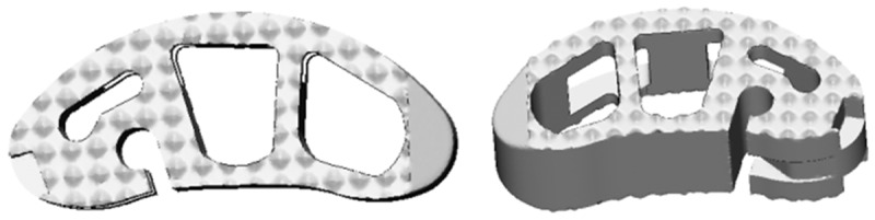
The interbody cages were modeled based on direction-changeable cage (Sanyou Inc., Shanghai, CN). The cages were imported into ANSYS software (ANSYS, Ltd., USA) (Figure 2). The material of the cages was PEEK. The pedicle screws were modeled based on LumFix System (Sanyou, Inc, Shanghai, CN). The pedicle screws were made from titanium alloy (Ti6Al4V).
Figure 2.
CAD models of direction-changeable cage.
The FE of the intact lumbar spine was validated by comparing the range of motion of the L3-4 and L4-5 segments with those from the cadaveric study of the lumbar spine previously conducted by Shim et al. [16], and three different moments (2.5 Nm, 5.0 Nm, and 7.5 Nm) were applied to the superior surface of L3 while the inferior surface of L5 was fixed.
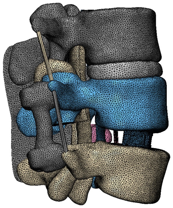
To simulate the surgical conditions, the L3-L5 segment was chosen to predict the biomechanical changes after inserting the cages with various positions. The interbody cage was inserted into the L3-L4 disc space laterally according to the clinical situation, followed by excision of unilateral facet joint of L4-5 vertebral body, preservation of spinous process and ligaments with supplemental bilateral pedicle screws (Figure 3). Three types of cage positions were applied (Figure 4): Type A referred to the lateral region, Type B referred to the lateralcentral region, and Type C referred to the anteriocentral region. All the surgical FE models were constructed based on the validated intact model. The interfaces of vertebrae and cages were also assigned to tie constraints. The bottom of L5 was fixed in all directions. The combined load of 280 N and 7.5 Nm were applied on the upper surface of L3 according to the literature [14,17]. The compressive load corresponded to the partial weight of human body. The moments simulated the different motion modes. Taking into account the symmetrical sagittal plane, four motion modes (flexion, extension, left bending, and left rotation) were simulated for surgical FE models in this study. The main biomechanical parameters were analyzed and exported, including ROM, IDP, cage stress and screw stress.
Figure 3.
The FE model of the L3-L5 implanted with direction-changeable cage and pedicle screws.
Figure 4.
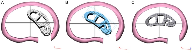
Three types of cage positions. A. Lateral region. B. The lateralcentral region. C. The anteriocentral region.
Results
Model validation
To validate our model, the ROM of L3-4 and L4-5 segments was compared with available experimental results. The ROM of the intact L3-L5 FE model in the sagittal plane for flexion-extension, the coronal plane for lateral bending and the axial plane for axial rotation was 17.1°, 17.8° and 9.7°, respectively, which was within the range of previous FE in vitro experimental studies [14-16].
Range of motion (ROM)
Under the combined load of 280 N and 7.5 Nm, the predicted ROM of surgical segment was shown in Figure 5. After implantation of interbody cage at different positions, the ROM at L4-L5 surgical level decreased substantially in all motion modes. Compared with the intact, ROM for Type A, Type B, and Type C decreased by 68.8, 69.1, and 65.1% in flexion, 66.1, 66.9, and 65.5% in extension, 75.9, 78.2, and 75.5% in bending, 66.3, 65.1, and 64.6% in rotation, respectively.
Figure 5.
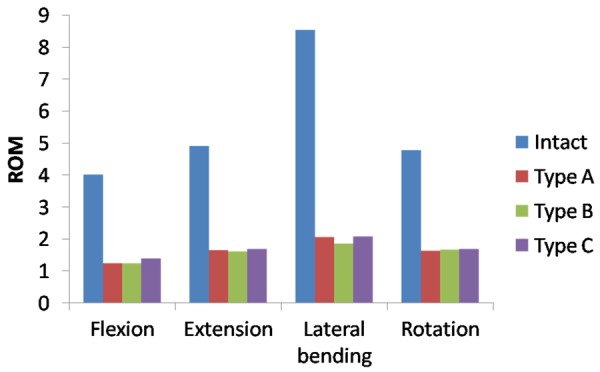
The ROM in FE model of the L3-L5 implanted with different direction-changeable cage positions.
Cage stress, IDP and screw stress
The maximal stress in cage was shown in Figure 6. The maximal stress in cage decreased in Type A, B and C in all motion modes except flexion and extension. The maximal stress was observed in left rotation motion with 720.5 MPa in Type A, in flexion motion with 707 MPa in Type B, in left rotation 397.3 MPa in Type C respectively. Compared with Type A, the maximal stress in Type B and C changed by 52.9, -67.8% in flexion, 44.4, -58.4% -61.35% in extension, -27.9, -63.5% in left lateral bending, -30.1, -44.9% in left rotation, respectively.
Figure 6.
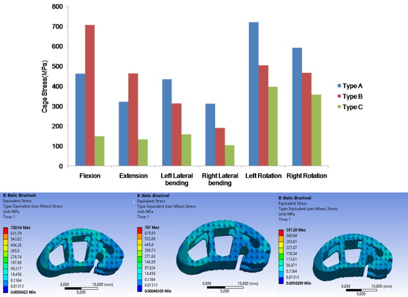
The maximal Von Mises stress on the different cages.
The IDP at L3-L4 adjacent level was shown in Figure 7. The maximal IDP was similar in the three types, with 1.6 MPa in left lateral bending in Type A, 1.5 MPa in flexion in Type B, and 1.4 MPa in flexion for Type C. Compared with Type A, the maximal IDP decreased in B and C in all motion modes except flexion.
Figure 7.
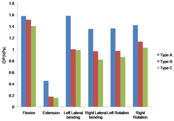
The maximal IDP of L3-L4 segement in FE model of the L3-L5 implanted with different direction-changeable cage positions.
The peak stress across the pedicle screws in different simulated models were presented in Figure 8. The stress was at minimum in rotation and maximum in extension. The range of peak stress was 16.4 to 61.1 MPa in Type A, 15.9 to 50.9 MPa in Type B, and 14.6 to 46.1 MPa Type C.
Figure 8.
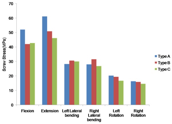
The maximal screw stress in FE model of the L3-L5 implanted with different direction-changeable cage positions.
Discussion
The lumbar cage has been widely used for spine fusion, and satisfactory bone fusion can effectively prevent postoperative cage shifting and postoperative intervertebral space height loss [18]. But cage-related complications have also raised concerns. Cage migration is one of the most common complications, and the shape of the cage has been proved be an important factor to cause migration. Zhao et al. retrospective studied the complications of cage migration in five spine centers, and the analysis showed that rectangular-shaped cages had a significantly greater incidence of cage migration (3.11%) than kidney-shaped cages (0.28%)[19]. In addition, improper cage placement is also an important cause of cage migration. While in practice, the position for cage placement is mainly decided according to the surgeons’ experience, and its adjustment is achieved with a pushrod under a fluoroscope.We have designed a direction-changeable kidney-shape cage, which could be easily and precisely placed at the midline of the spine [5,6]. Hence, In order to provide a biomechanics reference for surgeons to choose the position for implantation, we conduct this FE study and find its midline position could provide a better biomechanics result in cage stress, IDP and screw stress.
The major daily lumbar motions include flexion, extension, lateral bending, and rotation. In this study, we applied 3 different cage positions to observe the ROM changes, and the results showed that motion in all the directions decreased after cage fusion, which was position-independent and consistent with the literatures [20,21]. Lumbar cage fusion could stabilize the lumbar spine by reducing the ROM at the surgical level. IDP at adjacent levels decreased in Type A, B and C, particularly in extension, lateral bending and rotation, indicating that the anteriocentral position could further increase the risk of intervertebral disc degeneration at adjacent levels.
Stress shielding has been reported in lumbar cages [6,22], which could cause nonunion in the lumbar cage and lead to cage subsidence and migration. From the mechanical perspective, high stress can cause bone failure, and thus decreasing the stress might avoid the failure of bone contact [21]. In this study, we found that the maximal cage stress of Type A, B and C tended to decrease from 720.5 MPa to 397.3 MPa, with a 44.9% drop, which could decrease the risk of subsidence and migration. Overall, it indicated that the position of the cage placement could affect the release of the vertebral loads onto the cages.
Posterior implants can behave as a lever to further improve anterior support in the cage region. Biomechanical studies have shown higher stability of ALIF/FSF over ALIF [20]. Also a clinical study showed that the rate of displacement of PLIF segments is 16.7% and the rate of subsidence is 9.5%, while both values could decrease significantly if posterior fixation is applied [23]. In addition, in this study, the stress of posterior pedicle screw decreased with the change of the position of fusion cage. The maximal force was 61.1 MPa and decreased by 24.5% (46.1 MPa) from Type A to Type C. The screw stress data indicated that the position of the interbody cage could have a significant influence on the posterior hardware. And a position like anteriocentral may potentially improve the surgical outcome of TLIF by reducing posterior hardware-related complications
There are some limitations in this study, including applying one single lumbar model, simplifying the material properties of some tissues, ignoring the role of the muscle. Also the data might not represent the general population, especially these with degenerative spines. In addition, although the components of lumbar spine are nonlinear in reality, the material properties of them were simplified as linear elastic in this study. And we only examined 3 different cage positions in this study, and further studies are necessary for prostheses with more different positions.
In conclusion, according to the predicted results of the FE, the position of the direction-changeable cage could noticeably affect the biomechanics of lumbar spine. Comparing the cages with different positions, we found that the anteriocentral position cage showed advantages in lower cage stress, ODL and screw stress.
Acknowledgements
This study was funded by National Natural Science Foundation of China (81830077), and Social development fund of Shaanxi Province, China (2018SF-046).
Disclosure of conflict of interest
None.
References
- 1.Comer GC, Behn A, Ravi S, Cheng I. A biomechanical comparison of shape design and positioning of transforaminal lumbar interbody fusion cages. Global Spine J. 2016;6:432–438. doi: 10.1055/s-0035-1564568. [DOI] [PMC free article] [PubMed] [Google Scholar]
- 2.Holly LT, Schwender JD, Rouben DP, Foley KT. Minimally invasive transforaminal lumbar interbody fusion: indications, technique, and complications. Neurosurg Focus. 2006;20:E6. doi: 10.3171/foc.2006.20.3.7. [DOI] [PubMed] [Google Scholar]
- 3.Verla T, Winnegan L, Mayer R, Cherian J, Yaghi N, Palejwala A, Omeis I. Minimally invasive transforaminal versus direct lateral lumbar interbody fusion: effect on return to work, narcotic use, and quality of life. World Neurosurg. 2018;116:e321–e328. doi: 10.1016/j.wneu.2018.04.201. [DOI] [PubMed] [Google Scholar]
- 4.Hu YH, Niu CC, Hsieh MK, Tsai TT, Chen WJ, Lai PL. Cage positioning as a risk factor for posterior cage migration following transforaminal lumbar interbody fusion - an analysis of 953 cases. BMC Musculoskelet Disord. 2019;20:260. doi: 10.1186/s12891-019-2630-0. [DOI] [PMC free article] [PubMed] [Google Scholar]
- 5.Zhang H, Miao Q, Hao D, Zhao Q, He S, Wang B. Direction-changeable cage reduces X-ray exposure in treating isthmic lumbar spondylolisthesis: a retrospective study. Am J Transl Res. 2019;11:1066–1072. [PMC free article] [PubMed] [Google Scholar]
- 6.Zhang H, Jiang Y, Wang B, Zhao Q, He S, Hao D. Direction-changeable lumbar cage versus traditional lumbar cage for treating lumbar spondylolisthesis: a retrospective study. Medicine (Baltimore) 2018;97:e9984. doi: 10.1097/MD.0000000000009984. [DOI] [PMC free article] [PubMed] [Google Scholar]
- 7.Chen SH, Chiang MC, Lin JF, Lin SC, Hung CH. Biomechanical comparison of three stand-alone lumbar cages--a three-dimensional finite element analysis. BMC Musculoskelet Disord. 2013;14:281. doi: 10.1186/1471-2474-14-281. [DOI] [PMC free article] [PubMed] [Google Scholar]
- 8.Yang X, Song Y, Liu L, Liu H, Zeng J, Pei F. Anterior reconstruction with nano-hydroxyapatite/polyamide-66 cage after thoracic and lumbar corpectomy. Orthopedics. 2012;35:e66–73. doi: 10.3928/01477447-20111122-10. [DOI] [PubMed] [Google Scholar]
- 9.Pan FM, Wang SJ, Yong ZY, Liu XM, Huang YF, Wu DS. Risk factors for cage retropulsion after lumbar interbody fusion surgery: series of cases and literature review. Int J Surg. 2016;30:56–62. doi: 10.1016/j.ijsu.2016.04.025. [DOI] [PubMed] [Google Scholar]
- 10.Kimura H, Shikata J, Odate S, Soeda T, Yamamura S. Risk factors for cage retropulsion after posterior lumbar interbody fusion: analysis of 1070 cases. Spine (Phila Pa 1976) 2012;37:1164–1169. doi: 10.1097/BRS.0b013e318257f12a. [DOI] [PubMed] [Google Scholar]
- 11.Abbushi A, Cabraja M, Thomale UW, Woiciechowsky C, Kroppenstedt SN. The influence of cage positioning and cage type on cage migration and fusion rates in patients with monosegmental posterior lumbar interbody fusion and posterior fixation. Eur Spine J. 2009;18:1621–1628. doi: 10.1007/s00586-009-1036-3. [DOI] [PMC free article] [PubMed] [Google Scholar]
- 12.Yuan W, Zhang H, Zhou X, Wu W, Zhu Y. The influence of artificial cervical disc prosthesis height on the cervical biomechanics: a finite element study. World Neurosurg. 2018;113:e490–e498. doi: 10.1016/j.wneu.2018.02.062. [DOI] [PubMed] [Google Scholar]
- 13.Zhao X, Yuan W. Biomechanical analysis of cervical range of motion and facet contact force after a novel artificial cervical disc replacement. Am J Transl Res. 2019;11:3109–3115. [PMC free article] [PubMed] [Google Scholar]
- 14.Zhang Z, Fogel GR, Liao Z, Sun Y, Liu W. Biomechanical analysis of lumbar interbody fusion cages with various lordotic angles: a finite element study. Comput Methods Biomech Biomed Engin. 2018;21:247–254. doi: 10.1080/10255842.2018.1442443. [DOI] [PubMed] [Google Scholar]
- 15.Zhang Z, Li H, Fogel GR, Xiang D, Liao Z, Liu W. Finite element model predicts the biomechanical performance of transforaminal lumbar interbody fusion with various porous additive manufactured cages. Comput Biol Med. 2018;95:167–174. doi: 10.1016/j.compbiomed.2018.02.016. [DOI] [PubMed] [Google Scholar]
- 16.Schmidt H, Galbusera F, Rohlmann A, Zander T, Wilke HJ. Effect of multilevel lumbar disc arthroplasty on spine kinematics and facet joint loads in flexion and extension: a finite element analysis. Eur Spine J. 2012;21(Suppl 5):S663–674. doi: 10.1007/s00586-010-1382-1. [DOI] [PMC free article] [PubMed] [Google Scholar]
- 17.Choi J, Shin DA, Kim S. Biomechanical effects of the geometry of ball-and-socket artificial disc on lumbar spine: a finite element study. Spine (Phila Pa 1976) 2017;42:E332–E339. doi: 10.1097/BRS.0000000000001789. [DOI] [PubMed] [Google Scholar]
- 18.McAfee PC, DeVine JG, Chaput CD, Prybis BG, Fedder IL, Cunningham BW, Farrell DJ, Hess SJ, Vigna FE. The indications for interbody fusion cages in the treatment of spondylolisthesis: analysis of 120 cases. Spine (Phila Pa 1976) 2005;30:S60–65. doi: 10.1097/01.brs.0000155578.62680.dd. [DOI] [PubMed] [Google Scholar]
- 19.Zhao FD, Yang W, Shan Z, Wang J, Chen HX, Hong ZH, Qian Y, He DW, Fan SW. Cage migration after transforaminal lumbar interbody fusion and factors related to it. Orthop Surg. 2012;4:227–232. doi: 10.1111/os.12004. [DOI] [PMC free article] [PubMed] [Google Scholar]
- 20.Hueng DY, Chung TT, Chuang WH, Hsu CP, Chou KN, Lin SC. Biomechanical effects of cage positions and facet fixation on initial stability of the anterior lumbar interbody fusion motion segment. Spine (Phila Pa 1976) 2014;39:E770–776. doi: 10.1097/BRS.0000000000000336. [DOI] [PubMed] [Google Scholar]
- 21.Lee YH, Chung CJ, Wang CW, Peng YT, Chang CH, Chen CH, Chen YN, Li CT. Computational comparison of three posterior lumbar interbody fusion techniques by using porous titanium interbody cages with 50% porosity. Comput Biol Med. 2016;71:35–45. doi: 10.1016/j.compbiomed.2016.01.024. [DOI] [PubMed] [Google Scholar]
- 22.Togawa D, Bauer TW, Brantigan JW, Lowery GL. Bone graft incorporation in radiographically successful human intervertebral body fusion cages. Spine (Phila Pa 1976) 2001;26:2744–2750. doi: 10.1097/00007632-200112150-00025. [DOI] [PubMed] [Google Scholar]
- 23.Chen L, Yang H, Tang T. Cage migration in spondylolisthesis treated with posterior lumbar interbody fusion using BAK cages. Spine (Phila Pa 1976) 2005;30:2171–2175. doi: 10.1097/01.brs.0000180402.50500.5b. [DOI] [PubMed] [Google Scholar]