Abstract
A fluorescence lifetime-based water sensor was developed, based on a solvent-polarity-sensitive fluorescent metal-ligand compound, dipyrido1[3,2-a:2″,3″-c]phenazine, di[cis-1,2-bis(diphenylphosphino)-ethylene] osmium(II) hexafluorophosphate, [Os(dppz)(dppe)2](PF6)2. When excited in acetone solution, the compound emitted orange-red fluorescence with a peak wavelength of 610 nm. Fluorescence quenching was observed from both intensity and lifetime measurements when water was presented in the acetone. To fabricate a water sensor, the compound was immobilized by ionic bonding onto an ion-exchange resin, carboxymethyl cellulose, and then sandwiched between a thin sol-gel layer and a glass substrate. This formed a water-sensitive solid film sensor that, when re-inserted from a water-free into a water-containing organic solvent, displayed a lifetime decrease. The lifetime change could be measured in the frequency domain using phase-modulation fluorometry. Because of the long decay time of this compound the phase-modulation could be performed using an amplitude-modulated blue LED with a low modulation frequency near 2 MHz. For a change in the water content of an acetone solution from 0% to 20%, 39.6 degrees of phase angle decrease was observed. The degree of the change in phase angle varied from solvent to solvent. The typical response and recovery time for a 90% total signal change was a few seconds. The detection limit was solvent-dependent. When ethyl acetate was used as the solvent, the detection limit could be as low as 0.02% (v/v) of water. The sensor also displayed very good long term stability, as little change in performance was discoverable after two months.
Keywords: Fluorescence, Lifetime-based sensing, Solid state sensor, LED
1. Introduction
Optical sensors have been widely studied, developed, and used in the fields of bio-engineering, environmental science and industry [1–4]. Such sensors are attractive because they are inexpensive, miniature, robust, and easy to fabricate. The key element in an optical sensor is the indicator – a chemical substance which displays changes in its optical properties (such as absorbance, fluorescence intensity and fluorescence lifetime) upon interacting chemically or physically with the analyte of interest. One such interaction, known as solvation, may result in a phenomenon called solvatochromism, provided that the indicator molecule shows electronic transition energy differently in a polar media from that in a non-polar media [5]. In this case, the spectral and/or lifetime characteristics of the solvent-polarity-sensitive indicator changes with the variation of the polarity of its surrounding solvent, as the analyte concentration changes. Such solvent-polarity-sensitive indicators are commonly referred to as solvatochromic dyes. Sensors based on solvatochromism have been reported for sensing odors of organic compounds [6], alcohol [7–10] and water [11] in a less polar media.
A water sensor is of interest in numerous applications. For example, in the petroleum industry, on-line determination of the water content of oil-in-water emulsion is an important issue for crude oil processing and oil transportation. Sensors based on specific admittance measurement [12] and a densimeter [13] have been built for this purpose. A water sensor can also be used for the measurement of water in organic solvents, which is generally the most common impurity in organic solvents. Bai and Seitz [14] demonstrated a fiber optic sensor for measuring water in organic solvents, based on polymer swelling. In their studies, the size of the bead of anion exchange resin varied continuously with the water content in organic solvents, which induced the movement of a reflecting diaphragm, and therefore, changed the intensity of light reflected into an optical fiber. Kessler et al. [11], on the other hand, described an optical sensor for on-line determination of solvent mixtures (such as water in organic solvents), using a solvent-polarity-sensitive ketocyanine dye. The dye was immobilized on an ion-exchange membrane, and displayed fluorescence spectral changes upon exposure to solvents with different polarity. When the sensor was used for sensing water in ethanol by monitoring the intensity change at 620 nm, a sensitivity range of 0–20% of water and a response time of 15 s were obtained. While novel and interesting, this sensor was subject to photobleaching of the indicator dye. This limits its use as a practical sensor. Water sensors based on various sensing mechanism also include a holographic sensor for water in solvents [15], a water sensor utilizing the optical loss due to fiber bending when water seeps into splicing enclosures in optical fiber networks [16], water sensors based on polymer coated platinum electrodes [17], and an IR water sensor [18]. Despite the importance of water sensors, there are surprisingly few water sensors reported so far.
In contrast to intensity-based sensors, fluorescence lifetime-based sensing is insensitive to signal drift resulting from leaching and photobleaching of indicator dye, variations of light source intensity, and stability of the photodetector. Recently, we have demonstrated that fluorescence lifetime-based sensing for methanol [7], pH [19], CO2 [20], NH3 [21] and glucose [22] could be realized in the frequency domain [23], using the technique of phase-modulation fluorometry. In this method, a modulated excitation light source is used, which forces the emission light of the indicator fluorophore to also be modulated, but with a lifetime-dependent delay in phase angle and decrease in modulation. At a certain modulation frequency, a lifetime increase is reflected as an increase in phase angle and a decrease in modulation. Therefore, either the phase angle or modulation can be used as the sensing parameter. Since the phase angle is insensitive to the geometry of a solid sample, it is more convenient to use the phase angle to represent the lifetime.
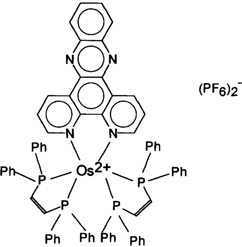
In this paper, we describe a fluorescence lifetime-based sensor for water, which contains a fluorescent metal-ligand compound, dipyridol[3,2-a:2″,3″-c]phenazine, di[cis-1,2-bis(diphenylphosphino)-ethylene] osmium(II) hexafluorophosphate, [Os(dppz)(dppe)2](PF6)2 (Scheme l), immobilized on an ion-exchange resin, carboxymethyl cellulose. The motivation for this osmium compound design is the work of Barton, Turro and co-workers [24] who showed that ruthenium complexes containing the dppz ligand were fluorescent when bonded to DNA, but were not fluorescent in water. The suggested mechanism was quenching due to interaction of water with the exposed heterocyclic nitrogen in the dppz ligand. Hence, it seems logical to consider such complexes for use as sensors for the presence of water.
Scheme 1.
Structure of [Os(dppz)(dppe)2](PF6)2.
2. Experimental section
2.1. Materials
The [Os(dppz)(dppe)2](PF6)2 was synthesized, purified, and identified at the Center for Fluorescence Spectroscopy, University of Maryland at Baltimore [25]. The cation exchange resin, carboxymethyl cellulose (or CM23, a Whatman product) and molecular sieves (type 4A, grade 514, and 8–12 mesh) were ordered from Fisher Scientific (Pittsburgh, PA). Water (HPLC grade), methanol (99.9+%, HPLC grade), acetone (99.5+%, spectrophotometric grade), acetonitrile (99.9+%, HPLC grade), 1,4-dioxane (99+%), N,N-dimethyl formamide (ACS reagent) and tetramethyl orthosilicate, TMOS, (99+%) were purchased from Aldrich (Milwaukee, WI). USP grade pure ethyl alcohol was from Werner–Graham Co. (Cockeysville, MD). Ethyl acetate (Baker analyzed reagent) was obtained from J.T. Baker Chemical Co. (Phillipsburg, NJ).
2.2. Sensing film preparation
The preparation of the sensing film involved two steps: loading [Os(dppz)(dppe)2](PF6)2 onto CM23 and producing the sol-gel film. To load the OS compound onto CM23, 2.5 mg of the compound was dissolved in 0.5 ml of a 1 : 1 (v : v) mixture of acetone and water. Then, 4.4 mg of CM23 powder was added into the solution, and the suspension was shaken until the color of CM23 powder changed from white to orange. The suspension was then centrifuged to allow the sediment of the CM23 particles. After the supernatant was removed, the powder was washed with the 1 : 1 acetone and water solution. These procedures-centrifugation, separation and washing, were repeated several times until the supernatant phase of the washed powder appeared colorless. The powder was dried in a 60°C oven overnight, and then suspended in 200 μl of methanol. After shaking, 10 μl of the suspension was spread onto either the surface (about 0.5 cm×0.5 cm) of a quartz glass slide (for equilibrium studies) or the front inner-side wall (about 10 cm×0.1 cm) of a flow cell (for time-dependent response and recovery measurements).
The sol-gel film was prepared based on a modified NH4OH catalyzed TMOS system [26]. The base-catalyzed system was preferred because much shorter time was required for the hydrolysis and condensation during the sol-gel formation, compared with that required by HCl catalyzed systems [27]. In this procedure, into 0.5 ml of TMOS were added 0.66 ml of methanol, 0.22 ml of water, 30 μl of N,N-dimethyl formamide and 30 μl of ammonia solution (pH 11.20). After mixing and standing for 10 min, 10 μl of the solution was applied on top of the pre-prepared thin layer of the loaded CM23, which formed the sensing film after drying in ambient atmosphere overnight. As phase-modulation measurements are intensity-insensitive, no attempt was made to produce uniform and reproducible films so as to avoid variations in fluorescence intensity yield from different film slides or different spots on each film.
2.3. Measurements
Absorption spectra were measured using a Hewlett-Packard 8452A UV/Vis Diode Array Spectrophotometer (Palo Alto, CA). Fluorescence spectra and phase-modulation measurements were carried out using an ISS K2 Multifrequency Phase and Modulation Fluorometer (Champaign, IL). In the emission spectrum measurements, a xenon arc lamp was used as the light source, with the band-pass settings of 8 nm and 16 nm for the excitation and emission monochromators, respectively. In the phase-modulation measurements, the light source used was a blue LED (NLPBSOO, Nichia America Co., Lancaster, PA), with an emission maximum of around 450 nm. The light output of the LED was amplitude-modulated as described previously [28]. Light from the LED with a wavelength more than 500 nm was cut off by placing a set of short-wave-pass filters (5OOFLO7, 6OOFLO7 and 7OOFLO7, Andover, Salem, NH) in the excitation path. The fluorescence was collected between 600–700 nm through an Andover 600FH90 long-wave-pass filter and a 700FL90 short-wave-pass filter, to prevent scattered-light from coming through. The lifetime reference solution used was a 10−5 M solution of Texas Red in water, with an assumed reference lifetime of 4 ns. The reference intensity was adjusted by adding proper neutral density filter(s) in its emission path to match the emission light intensity from the film sensor. In all phase angle measurements (except the time-dependent measurements), the measurement error was statistically pre-set as 0.2°. The instrument collected and averaged the signal until this criterion was met. The measurement procedures and apparatus setup for the equilibrium studies was very similar to that described in our previous paper [7]. The film sensor supported on the quartz glass slide was fixed in a quartz fluorescence cuvette at an orientation of about 60° to the excitation light beam. Then, 3 ml of the desired organic solvent mixture with a certain percentage of water was pipetted into the cuvette, and the phase angle and modulation were measured 2 minutes later. Water-free solvents were obtained by adding molecular sieves into the solvents 24 h prior to use. In the time-dependent response and recovery studies, a modified stopped-flow system (Hi-Tech Scientific, Surrey, England) was employed. The flow cell of the system was cut at the bottom of the sampling cavity to allow the sensing film to be cast on the inner wall of the front quartz window. The cell was re-sealed by putting a piece of Teflon membrane, an o-ring and a cubic glass spacer under the bottom of the cavity, and squeezed together with the upper part of the cell through a pair of screws. The desired solvent and its water mixture were then alternately administrated into the cell through two glass syringes provided with the system. After use, the sensing film may be conveniently removed by dissolving it in a pH 11 NaOH solution. Except for the long-term stability study, a fresh sensor film was used in each experiment. Unless otherwise specified, all the measurements were performed at ambient temperature.
3. Results and discussion
3.1. Behavior of [Os(dppz)(dppe)2](PF6)2 in solution
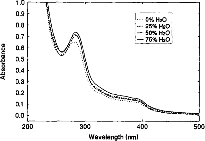
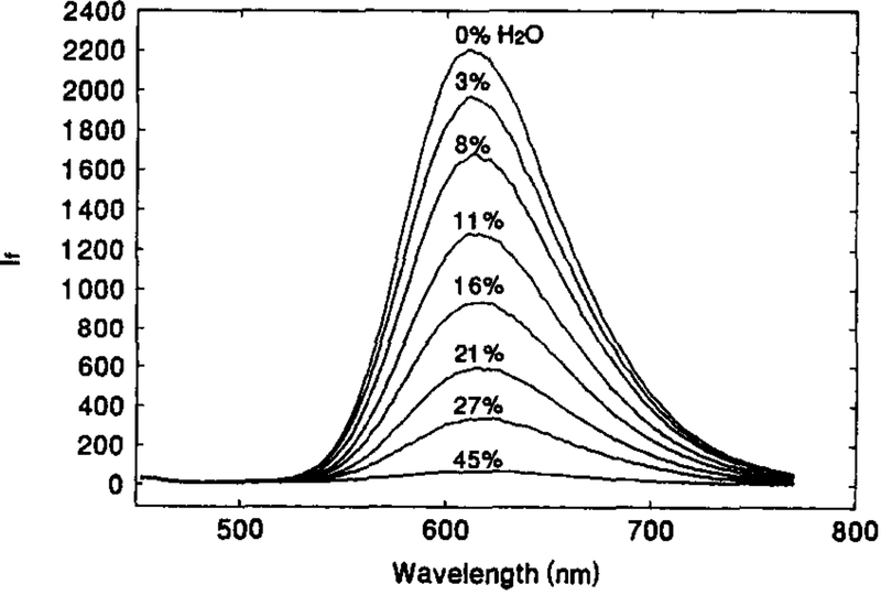
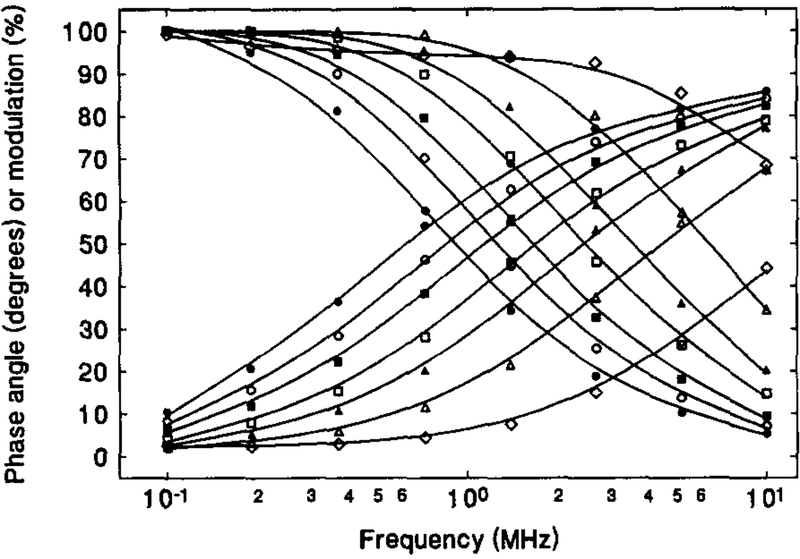
Fig. 1 shows the absorption spectra of 1.1 × 10⁻⁵ M solution of [Os(dppz)(dppe)2](PF6)2 in acetonitrile containing various amount of water. Absorption peaks are observed at around 284 nm, with broad shoulders in between 300 to 400 nm. In the range of 0–75% water, neither the peak position nor the absorbance are found to practically be water-sensitive. In contrast, the emission spectra of the OS compound solution are highly water-dependent. Fig. 2 illustrates the change in emission spectra with the change in water content of an acetone solution. Though the emission peak at 610 nm remains constant, the peak intensity drops dramatically with increasing water content, i.e. the fluorescence intensity from the solution containing 45% water was only some 4% of that from the water-free solution. This significant water quenching effect can also be seen in the phase-modulation measurements (Fig. 3). As the water content increases, the phase angle values decrease and modulation values increase. This is an indication of reduction in the fluorescence lifetime of the OS compound. At 2 MHz where the maximum phase angle changes are achieved, an increase in water content from 0% to 43% causes a decrease of 59° in phase angle and an increase of about 65% in modulation. This indicates that the compound is a very good water-sensitive indicator, and suitable for constructing a water sensor.
Fig. 1.
Absorption spectra of 1.1 × 10⁻⁵ M [Os(dppz)(dppe)2](PF6)2 in acetonitrile containing different amount of water.
Fig. 2.
Water-dependent emission spectra of 1.1 × 10⁻⁵ M [Os(dppz)(dppe)2](PF6)2 in acetone with various amount water.
Fig. 3.
Variation of phase-modulation with water content for 1.1 × 10⁻⁵ M [Os(dppz)(dppe)2](PF6)2 in acetone-water mixtures. The water contents are: 0% (•), 8% (○), 12% (■), 17% (□), 21.5% (▲), 29 (△) and 43% (◊).
3.2. Characterization of the sensing film
The sensing film was characterized in six common organic solvents containing various amount of water. The solvents used included acetone, acetonitrile, 1,4-dioxane, ethanol, ethyl acetate and methanol, which are listed in Table 1 along with their values of empirical solvent polarity parameter, , in an increasing order (where, is normalized ET(30)-the empirical parameter of solvent polarity, defined as the molar electronic transition energy of the negatively solvatochromic dye, pyridinium N-phenolate betaine, dissolved in a desired solvent [5]). For each solvent, we identified the modulation frequency where the phase angle exhibited a maximum change. Then, the phase angle change was calibrated against water content, and the response and recovery behavior of the sensing film in the water-containing and water-free solvent was examined. The results of using acetone as the solvent are presented in figures, while those for the remaining solvents are summarized in Table 1.
Table 1.
Characteristics of the sensing film in six organic solvents containing various amount of water
| Solvent | a | Δϕ(°)b | Detection limit (%,v/v)c | Response time (s)d | Recovery time (s)e |
|---|---|---|---|---|---|
| 1,4-Dioxane | 0.164 | 24.7 | 0.10 | 6 | 10 |
| Ethyl acetate | 0.228 | 35.5 | 0.02 | 7 | 10 |
| Acetone | 0.355 | 39.6 | 0.13 | 4 | 11 |
| Acetonitrile | 0.460 | 37.4 | 0.06 | 6 | 7 |
| Ethanol | 0.654 | 28.0 | 0.31 | 6 | 8 |
| Methanol | 0.762 | 26.1 | 0.68 | 13 | 10 |
| Water | 1.000 | — | — | — | — |
, where ET(30) of a solvent is the molar electronic transition energy of pyridinium N-phenolate betaine dissolved in it. values are from [5].
For a change in water content from 0% to 20%. Measured at 1 or 2 MHz.
Values are estimated from the calibration curves for each solvent at the signal level of three times of the noise level (i.e. 3×0.2°).
Time for a 90% of the total signal change when water content increases from 0% to 20%.
Time for a 90% of the total signal change when water content decreases from 20% to 0%.
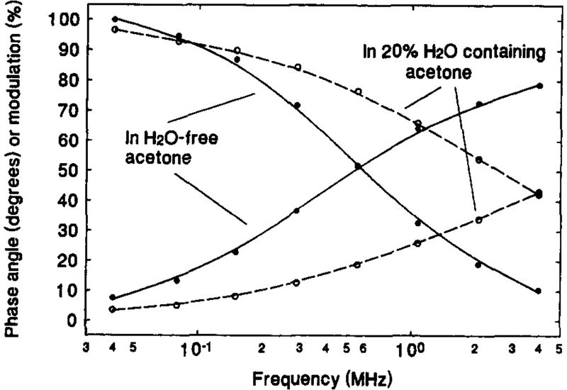
Fig. 4 shows the dependence of the phase angle and modulation (and therefore, the lifetime) on the concentration of water in acetone for the OS compound in the sensing film. Similar to the results shown in Fig. 3 for the OS compound in solution, the phase angle and modulation curves significantly shifted to higher frequency as the solvent was changed from water-free acetone to 20% water in acetone. This behavior of the sensing film was also found when other solvents were used in place of acetone. For all six solvents, the frequency where the phase angle displayed maximum change fell between 1 and 2 MHz, at which the LED may be conveniently modulated [7]. Table 1 gives the phase angle change, Δϕ, for each solvent for an increase in the water content from 0 to 20%. A maximum of 39.6° and minimum of 24.7° change in phase angle were observed when acetone and 1,4-dioxane were used as the solvents, respectively. As the solvent polarity, , of the solvents used ranges broadly from 0.164 to 0.762, one may predict that the sensor is useful for measuring water in most organic solvents.
Fig. 4.
Variation of phase-modulation with water content for [Os(dppz)(dppe)2](PF6)2 film sensor in water-free acetone (solid lines) and 20% water in acetone (dashed lines).
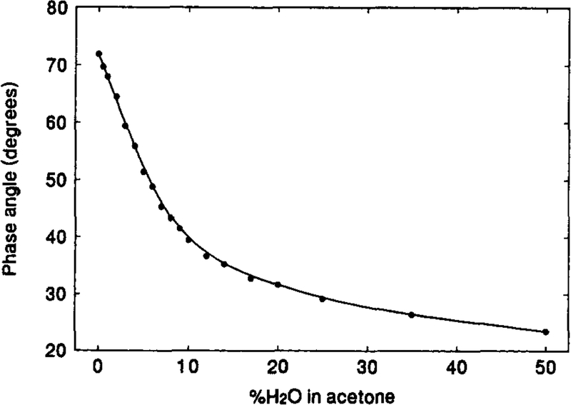
Fig. 5 represents the calibration curve of the phase angle against the water content in acetone. The sensor shows the greatest equilibrium-response in the range of 0%–10% of water. As the noise level of the measurements is about 0.2° [7], a detection limit (three times of the noise level) of approximate 0.13% of water can be estimated from the calibration curve at the water concentration corresponding to the initial 0.6° drop in phase angle. Similarly, the detection limits of water in the other solvents are obtained, which are given in Table 1. The lowest detection limit is 0.02% of water in ethyl acetate. It seems that the detection limit is lower in the less polar solvents.
Fig. 5.
Calibration curve of phase angle against water content for the [Os(dppz)(dppe)2](PF6)2 film sensor in acetone-water mixture.
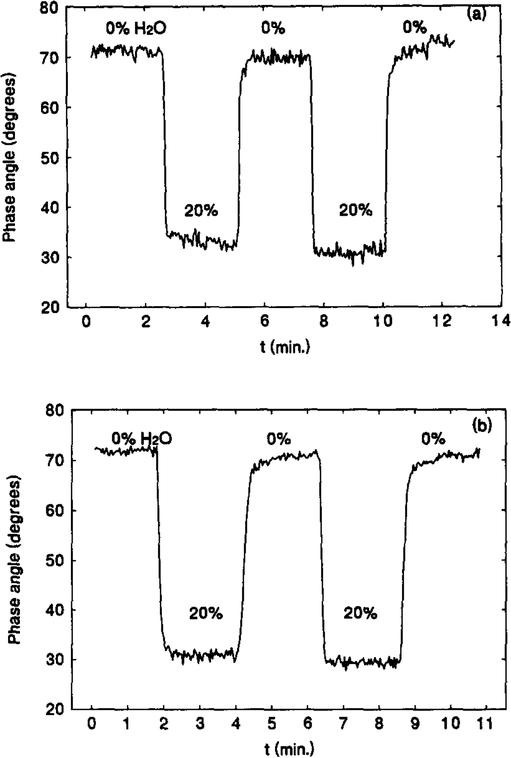
Fig. 6(a) is a typical time-dependent response and recovery profile displayed by a freshly prepared sensor in water-free acetone and a 20% water-containing acetone solution. When exposed to the 20% water-containing acetone solution, the sensor showed a sharp drop in phase angle of 40°, and this was fully recoverable upon re-exposure to the water-free acetone. The processes of response and recovery are very fast – both are completed in seconds. Table 1 lists the values of t90% s, the response and recovery times for a 90% of the total signal change, for the six solvents. Most of the values are within 10 s. These response and recovery characteristics of the sensor appear to remain for months. This is seen from Fig. 6(b). Fig. 6(b) represents the response and recovery profile measured using a two month old sensing film stored in a normal lab environment without any special treatment. After washing several times with a water-free acetone, the measurements were performed. The margined difference between Fig. 6(a) and (b) indicates excellent stability of the sensing film over the long term. The only drawback found so far is the gradual wash-off of the loaded CM23 particles from the matrix, due to degradation of the sol-gel matrix. Though it does not affect the use of the film as a lifetime-based sensor because phase angle measurement is intensity-insensitive, it may limit the usable lifetime of the sensor when the intensity becomes too low for the signal to be efficiently collected. Changing of a sol-gel system which has less shrinkage effect may provide a solution for this problem.
Fig. 6.
(a) Time-dependent response and recovery of a fresh [Os(dppz)(dppe)2](PF6)2 film sensor in water-free and 20% water-containing acetone solution. (b) Time-dependent response and recovery of a two-month-old [Os(dppz)(dppe)2](PF6)2 film sensor in water-free and 20% water-containing acetone solution.
4. Conclusion
A lifetime-based fluorescence water sensor was developed by immobilizing the metal-ligand fluorophore, [Os(dppz)(dppe)2](PF6)2, onto an ion-exchange resin, CM23, which was covered with a sol-gel thin layer. The lifetime decay of the sensor in water-containing media can be monitored in frequency domain, using a low cost blue LED as the excitation light source. This sensor exhibited a 39.6 degrees phase angle decrease at 2 MHz when placed from a water-free acetone into a mixture of 20% water in acetone. Phase angle decreases were also found for another five organic solvents which contained water. The response and recovery was completed in seconds. The measurement of the response and recovery profile of a two months old sensing film showed little difference from that of freshly prepared film, indicating the sensor is very stable. The detection limit depends on the solvent used. It can be as low as 0.02% of water in ethyl acetate. The sensor can be used to measure the water content in a blend of water with a less polar organic solvent, especially when water content is between 0 and 20%.
Acknowledgements
Financial support for this research from the National Science Foundation (grants: BES-9413262 and BCS-9157852), the National Institute of Health (grants: RR-08119 and RR-07510), and Genentech, Inc. is gratefully acknowledged. The authors also thank Dr. J. J. Cannon of Pfizer for his encouragement, and Mr. Michael Frizzell for his excellent work on modifying the stopped-flow system.
References
- [1].Wolfbeis OS (Ed.), Fiber Optic Chemical Sensors and Biosensors, Vols. I and II, CRC Press, Boca Raton, FL, 1991. [Google Scholar]
- [2].Lakowicz JR (Ed.), Topics in Fluorescence Spectroscopy, Vol. 4: Probe Design and Chemical Sensing, Plenum Press, New York, 1994. [Google Scholar]
- [3].Seitz WR, CRC Crit. Rev. Anal. Chem, 19 (1988) 135. [Google Scholar]
- [4].Rao G, Bambot SB, Kwong CW, Szmacinski H, Sipior J, Holavanahali R and Carter G, in: Lakowicz JR (Ed.), Topics in Fluorescence Spectroscopy, Vol. 4: Probe Design and Chemical Sensing, Plenum Press, New York, 1994, pp. 417–448. [Google Scholar]
- [5].Reichardt C, Chem. Rev, 94 (1994) 2319. [Google Scholar]
- [6].Dickinson TA, White J, Kauer JS and Walt DR, Nature, 382 (1996) 697. [DOI] [PubMed] [Google Scholar]
- [7].Chang Q, Lakowicz JR and Rao G, Analyst (London), 122 (1997) 173. [Google Scholar]
- [8].Hubert C, Fichou D, Valat P and Gamier E, Polymer, 36 (1995) 2663. [Google Scholar]
- [9].Orellana G, Gomez-Cameros AM, de Dios C, Garcia-Martinez AA and Moreno-Bondi MC, Anal. Chem, 67 (1995) 2231. [Google Scholar]
- [10].Rottman C, Grader GS, de Hazan Y and Avnir D, Langmuir, 12 (1996) 5505. [Google Scholar]
- [11].Kessler MA, Gailar JG and Wolfbeis OS, Sens. Actuators (B), 3 (1991) 267. [Google Scholar]
- [12].Garcia-Golding F, Giallorenzo M, Moreno N and Chang V, Sens. Actuators A, 46–47 (1995) 337. [Google Scholar]
- [13].Liu R, Xi X and Liang C, SPIE, 1572 (1991) 399. [Google Scholar]
- [14].Bai M and Seitz WR, Talanta, 41 (1994) 993. [DOI] [PubMed] [Google Scholar]
- [15].Blyth J, Millington RB, Mayes AG, Frears ER and Lowe CR, Anal. Chem, 68 (1996) 1089. [DOI] [PubMed] [Google Scholar]
- [16].Tomita S, Tachino H and Kasahara N, J. Lightwave Technol, 8 (1990) 1829. [Google Scholar]
- [17].Clough AE, Anal. Chim. Acta, 315 (1995) 15. [Google Scholar]
- [18].Hishikari I, Myauchi K and Shimizu T, Japanese Patent JP 08159965 (1996).
- [19].Szmacinski HS and Lakowicz JR, Anal. Chem, 65 (1993) 1668. [DOI] [PMC free article] [PubMed] [Google Scholar]
- [20].Sipior J, Bambot S, Romauld M, Carter GM, Lakowicz JR and Rao G, Anal. Biochem, 227 (1995) 309. [DOI] [PMC free article] [PubMed] [Google Scholar]
- [21].Chang Q, Sipior J, Lakowicz JR and Rao G, Anal. Biochem, 232 (1995) 92. [DOI] [PMC free article] [PubMed] [Google Scholar]
- [22].Lakowicz JR and Maliwal BP, Anal. Chim. Acta, 271 (1993) 155. [Google Scholar]
- [23].Lakowicz JR, Principles of Fluorescence Spectroscopy, Plenum Press, New York, 1983. [Google Scholar]
- [24].Jenkins Y, Friedman AE, Turro NJ and Barton JK, Biochem, 31 (1992) 10809. [DOI] [PubMed] [Google Scholar]
- [25].Murtaza Z and Lakowicz JR, unpublished observations.
- [26].Klein LC (Ed.), Sol-gel Technology for Thin Films, Fibers, Preforms, Electronics, and Specialty Shapes, Noyes Pub, Park Ridge, NJ, 1988, p. 202. [Google Scholar]
- [27].Hench LL and West JK, Chem. Rev, 90 (1990) 33. [Google Scholar]
- [28].Sipior J, Carter GM, Lakowicz JR and Rao G, Rev. Sci. Instrum, 67 (1996) 3795. [Google Scholar]


