Abstract
Multi-element high-intensity focused ultrasound phased arrays in the shape of hemispheres are currently used in clinics for thermal lesioning in deep brain structures. Certain side effects of overheating non-targeted tissues and skull bones have been revealed. Here, an approach is developed to mitigate these effects. A specific design of a fully populated 256-element 1-MHz array shaped as a spherical segment (F-number, F# = 1) and filled by randomly distributed equal-area polygonal elements is proposed. Capability of the array to generate high-amplitude shock fronts at the focus is tested in simulations by combining three numerical algorithms for linear and nonlinear field modeling and aberration correction. The algorithms are based on the combination of the Rayleigh integral, a linear pseudo-spectral time domain Kelvin–Voigt model, and nonlinear Westervelt model to account for the effects of inhomogeneities, aberrations, reflections, absorption, nonlinearity, and shear waves in the skull. It is shown that the proposed array can generate nonlinear waveforms with shock amplitudes >60 MPa at the focus deep inside the brain without exceeding the existing technical limitation on the intensity of 40 W/cm2 at the array elements. Such shock amplitudes are sufficient for mechanical ablation of brain tissues using the boiling histotripsy approach and implementation of other shock-based therapies.
I. INTRODUCTION
Development of noninvasive methods for irradiating deep brain structures through an intact skull using high-intensity focused ultrasound (HIFU) has been the subject of intensive studies during the last several decades. In transcranial HIFU surgery, an ultrasound beam is focused through skull bones to predetermined brain sites and induces local heating and subsequent thermal destruction of the brain tissue (Hynynen and Jolesz, 1998). This method has been successfully applied clinically, in particular for treating intracerebral tumors (McDannold et al., 2010), chronic neuropathic pain (Jeanmonod et al., 2012), essential tremor (Elias et al., 2013), and trigeminal neuralgia (Monteith et al., 2013). The majority of treatments were conducted using ultrasound arrays of the magnetic resonance (MR)-guided ExAblate clinical systems (InSightec Ltd., Tirat Carmel, Israel), which comprise 1024 elements distributed evenly at the surface of hemispherical transducers of 300 mm diameter positioned over the head of a patient (Hynynen and Jones, 2016).
Despite undoubted advantages of this approach, certain drawbacks in its clinical application have been revealed. In clinical settings, the array is fixed relative to the head of a patient so that its center of curvature is located close to the center of the skull. A hemispherical array design does not allow for mechanical displacement of its focus of more than 2 cm from the center of the head. For the existing array geometry and clinically used frequencies of 650–710 kHz, electronic steering of the focus by changing phases at the array elements provides satisfactory focusing quality only in a relative proximity to the geometrical focus of the array. Therefore, only relatively small brain volumes located in the central part of the head with a radius of approximately 25 mm can be treated. New array designs, due to smaller focusing angle, would potentially allow an enlargement of the HIFU treatment volume in the brain by moving and rotating the transducer. In addition, for such arrays pulsed exposures with higher peak power and low duty cycle would provide nonlinear enhancement of heat deposition at the focus, thus diminishing diffusion effects and skull heating.
The boiling histotripsy approach for mechanical tissue ablation, which relies on nonlinear propagation effects, has a potential to diminish the existing side effects of thermal HIFU in the brain (Khokhlova et al., 2011). However, it has been recently shown that with a hemispherically shaped acoustic source and clinically relevant power outputs of the system (<800 W), the nonlinear effects are negligible (Sapozhnikov et al., 2016). The major factors for weakening nonlinear effects are the relatively low frequency and short length of the focal lobe (about 4 mm) of the arrays. For comparison, the length of the main focal lobe of HIFU transducers with frequencies typically higher than 1 MHz and F# of about one is much larger (about 20–30 mm; Rosnitskiy et al., 2017a). Therefore, novel therapeutic approaches that utilize formation of shocks cannot be realized with the hemispherical array geometry.
Ultrasound arrays shaped as a spherical segment with smaller angle of convergence have been also used as clinical prototypes for HIFU treatments in the brain. A 512-element array with aperture of about 230 mm, circular elements of 6 mm diameter, and frequency bandwidth of 0.8–1.3 MHz has been used in developing linear thermal sonication protocols when irradiating through cadaver skulls with aberration correction (Marsac et al., 2017; Chauvet et al., 2013). A 1.2-MHz array of the clinical Sonalleve V1 system (Philips Healthcare, Vantaa, Finland) has been successfully used for boiling histotripsy (BH) mechanical ablation in the brain of piglets with the skull bone removed (Looi et al., 2016). The feasibility of cavitation histotripsy in agarose tissue phantoms and ex vivo canine liver through an intact human skull immersed in water has been demonstrated in laboratory experiments using 250 kHz and 500 kHz frequencies (Kim et al., 2014). This approach relied on using low frequencies for reaching very high negative pressures without shock formation, corresponding nonlinear saturation effects, and aberrations of the generated high frequencies. Cavitational histotripsy was also realized in vivo in porcine cortex after a craniectomy, i.e., without propagation through the skull (Sukovich et al., 2018).
Recently, capabilities of arrays having relatively small aperture angles, similar to the Sonalleve V1 and V2 systems (Philips Healthcare, Vantaa, Finland), for generating nonlinear fields in transcranial applications were examined in simulations (Rosnitskiy et al., 2017a). A model of a 1-MHz array in the shape of a spherical segment with a diameter and radius of curvature of 200 mm (F# = 1) was proposed. The array aperture is 33% smaller, and the convergence angle is three times smaller than those of the 300 mm diameter hemispherical arrays of the ExAblate systems (InSightec Ltd., Tirat Carmel, Israel). The proposed array can be moved mechanically toward or away from the skull, as well as turned around the patient's head providing the potential for significant enlargement of the volume for treatments inside the head. It was shown that taking into account current intensity limitations at the array elements and acoustic energy losses in the skull, such an array can generate shocks at the focus in the brain if skull-induced aberrations are corrected. The presence of high-amplitude shocks at the focus while having much lower amplitude and less distorted waveforms close to the skull would significantly enhance the thermal effect on the brain locally at the focus, and thus reduce the risk of overheating the skull. In addition, pulsed HIFU sequences with high peak pressure in combination with a corresponding lower duty cycle can be used to generate thermal lesions in brain tissues closer to the skull than currently possible. Moreover, at very low duty cycle, the boiling histotripsy approach can be applied to mechanically disintegrate the desired tissue volumes with high precision, practically without thermal effects or side effects related to overheating overlaying tissues (Khokhlova et al., 2015). Therefore, the approach of using relatively small aperture angles proposed in Rosnitskiy et al. (2017a) has a potential for expanding the possibilities of transcranial ultrasound surgery.
However, these recent numerical studies have also shown that generation of shocks at the focus in brain without exceeding safe intensity levels at the array surface and assuming that skull aberrations were corrected is feasible only for tightly packed arrays with a filling factor of >80% (Rosnitskiy et al., 2017a). Here, the filling factor is defined as the ratio of the total area of all elements of the array and the area of the array shell on which the elements are positioned. In addition, distribution of the elements in such arrays should be non-periodic to avoid formation of side lobes when electronic focus steering is used (Gavrilov and Hand, 2000).
Various models of non-periodic tightly packed arrays have been developed recently (Raju et al., 2011; Stephens et al., 2011; Pinton et al., 2012; Gavrilov et al., 2015; Morrison et al., 2014; Khokhlova et al., 2016; Ramaekers et al., 2017a; Ramaekers et al., 2017b; Hand et al., 2009; Gavrilov and Hand, 2014). Designs with different spiral layout and geometry of the elements have been proposed (Stephens et al., 2011; Pinton et al., 2012; Gavrilov et al., 2015; Morrison et al., 2014; Khokhlova et al., 2016). An array model with very high filling factor using the elements shaped as Voronoi tessellation cells and positioned at Fermat's spiral was developed (Ramaekers et al., 2017a; Ramaekers et al., 2017b). However, the filling factors of such arrays with necessary technological gaps between the elements were still less than 80%. Recently, a random array with the maximum possible filling factor (100% if no gaps between elements needed in practice were introduced) was proposed (Rosnitskiy et al., 2018). The array is comprised of spherically curved elements shaped as polygons of equal area and randomly distributed in a mosaic pattern using the method of capacity-constrained tessellation (Balzer et al., 2009).
Before practical implementation of the proposed array and shock-based treatment design, a feasibility of realizing shock-forming conditions deep inside the brain should be demonstrated. Nonlinear simulations of trans-skull HIFU beams based on the use of a realistic model of the human head should be performed. A full acoustic model requires simulations of focused ultrasound beams propagating through the skin, skull, and brain tissues and inclusion of effects, such as reflection, aberration, absorption, and generation of shear waves, in the skull. Previously, various simulation approaches of differing complexity have been developed considering the skull as an attenuating liquid-type homogeneous layer of various thickness (Vyas and Christensen, 2012), taking into account shear waves (Treeby and Cox, 2014a; Treeby et al., 2014b) and internal structure of the bone (Aubry et al., 2003). The full nonlinear wave propagation problem has been simulated only for quasi-linear waveform distortion at the focus (IEC, 2007; Rosnitskiy et al., 2017b) using a graphics processing unit (GPU) implementation with 8 points per wavelength (Jing et al., 2012) and using parallel computing on several thousand cores with 16 points per wavelength (Jaros et al., 2016).
Various attempts have been undertaken to perform weakly nonlinear simulations (Sapozhnikov et al., 2016; Pinton et al., 2012). However, no algorithm exists that would enable modeling propagation through a realistic three-dimensional (3D) skull with strong nonlinear effects that result in formation of shocks at the focus.
In the present study, a method of combining various linear and nonlinear physical models in different regions of the HIFU beam is proposed and tested. The main idea of such a method is to use the most suitable and fast simulation models in the spatial regions with different acoustic properties. Specifically, the Rayleigh integral method and nonlinear Westervelt model were used in water outside the head, a linear pseudo-spectral time domain Kelvin–Voigt model—inside the skull and adjacent tissues (Treeby and Cox, 2014a) and a nonlinear Westervelt model—inside the homogeneous absorptive brain tissue. This approach was implemented for evaluating the distortion effect of the skull on shock formation and applying an aberration correction to compensate for such distortions.
The problem of compensating aberrations induced by the geometrical and acoustic characteristics of skull bones, which are patient specific, have been addressed in simulation studies using time reversal (Fink, 1992, 1997; Tanter et al., 1998; Aubry et al., 2003; Pernot et al., 2003) and phase conjugation methods (Hynynen and Jolesz, 1998; Hynynen and Sun, 1999; Clement and Hynynen, 2002). Experimental verification of the simulation data has been reported (Hynynen and Sun, 1999). Acoustic properties of the skull were reconstructed from magnetic resonance imaging (MRI; Hynynen and Sun, 1999) or computed tomography (CT; Aubry et al., 2003; Clement and Hynynen, 2002) scans. In the present study, the MRI data of the human head were used to set acoustic properties of the medium for modeling HIFU propagation through the intact skull and correcting aberrations induced by the skull. The study proposes a new aberration correction method that takes into account the pattern of the array, the shape of the head, and propagation of elastic waves in the skull.
The main goal of the paper is to demonstrate the feasibility of achieving formation of shocks in deep brain structures when focusing through the skull using a fully populated random array and introducing aberration correction. A simulation algorithm was developed that accounts for reflections from the skull bones, absorption and generation of shear waves in the skull, and nonlinear propagation effects in water and the brain. A new design of a fully populated array with random distribution of its elements (Rosnitskiy et al., 2018) was used in simulations. Field distortion effects were evaluated, and an aberration correction method was proposed and implemented in the modeling.
II. MATERIALS AND METHODS
A. Acoustic model of the human head
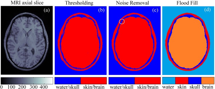
A realistic 3D model of the human head for acoustic simulations was created using a set of axial MRI images from an open database.1 The set contains 192 × 256-pixel axial MRI slices [Fig. 1(a)] for 91 different transverse planes passing through the head at different heights. The image has a spatial resolution (voxel size) of 1 mm × 1 mm × 1 mm, and the MR intensity scale ranges from 0 to 500 units. To partition the images into four segments (skin, skull, brain, and outer space filled with water), the following simple segmentation technique was used. First, a grayscale image was turned into a binary one using a thresholding method.
FIG. 1.
(Color online) Segmentation of the magnetic resonance imaging (MRI) data of the human head to construct a three-dimensional (3D) model of the propagation medium for acoustic simulation. (a) An example of an axial MRI slice. (b) Binary thresholding segmentation of the slice. (c) The result of noise removal. (d) Final segmentation of the slice into different types of tissues.
Pixels with MR scale values less than 80 were assigned to the type 1 “water/skull” and the rest to the type 2 “skin/brain” [Fig. 1(b)]. Then, the noise was removed from the images using an iterative algorithm. At each iteration, all the pixels of the image [Fig. 1(b)] were evaluated for the presence of more than two of four neighboring pixels (above, below, left, and right) of different type. If such presence was found, then the pixel was declared noisy and reassigned to the opposite type and repainted accordingly.
Then this process was repeated until no repaint actions were undertaken by either removing all noisy pixels or concentrating them as four-pixel clusters [circled in Fig. 1(c)] that can be automatically detected and removed [Fig. 1(c)]. Finally, the outer (a start node is in the upper-right corner of the image) and inner (a start node is in the center of the image) spaces were flood-filled with different colors to obtain the segmented image [Fig. 1(d)]. After segmentation, all 91 axial slices were combined to obtain the 3D model.
Different segments representing a human head surrounded by water (skin, skull, and brain) were considered homogeneous in this model (Treeby and Cox, 2014a). The acoustic parameters of the segments are listed in Table I. For viscoelastic simulations, the sound speeds , , absorption coefficients , for compressional and shear waves, densities ρ0, and nonlinearity coefficients β are also given in Table I.
TABLE I.
Acoustic parameters for linear and nonlinear simulations.
| Acoustic parameter | Water | Skin | Skull | Brain |
|---|---|---|---|---|
| Sound speed compressional cp (m/s; Van Dongen and Verweij, 2008; White et al., 2006; Duck, 1990) | 1500 | 1624 | 2820 | 1550 |
| Sound speed shear wave cs (m/s; White et al., 2006) | 0 | 0 | 1500 | 0 |
| Density ρ0 (kg/m3; Van Dongen and Verweij, 2008; White et al., 2006; Duck, 1990) | 1000 | 1109 | 1732 | 1030 |
| Absorption coefficient compressional for 1 MHz αp (dB/cm; Van Dongen and Verweij, 2008; White et al., 2006; Goss et al., 1979) | 0 | 1.84 | 8.83 | 0.21 |
| Absorption coefficient shear wave for 1 MHz αs (dB/cm; White et al., 2006) | 0 | 0 | 19.5 | 0 |
| Nonlinearity coefficient β (Duck, 1990) | 3.5 | — | — | 4.3 |
B. Array transducer model
Geometrical parameters of the multi-element ultrasound transducer were chosen in accordance with the previous study for a single-element transducer (Rosnitskiy et al., 2017a): radius of curvature F = 200 mm, aperture D = 200 mm, operating frequency f = 1 MHz. In this previous study it was shown that computationally economic evaluation of the level of nonlinear waveform distortion can be performed using the Khokhlov-Zabolotskaya-Kuznetsov (KZK) equation under assumption of the axial symmetry of the beam. The KZK-based modeler has been applied to the chosen transducer and it was found that the transducer with the proposed geometry, and tight packing of the elements (filling factor >80%) can provide shock amplitudes at the focus sufficient for mechanical tissue disintegration.
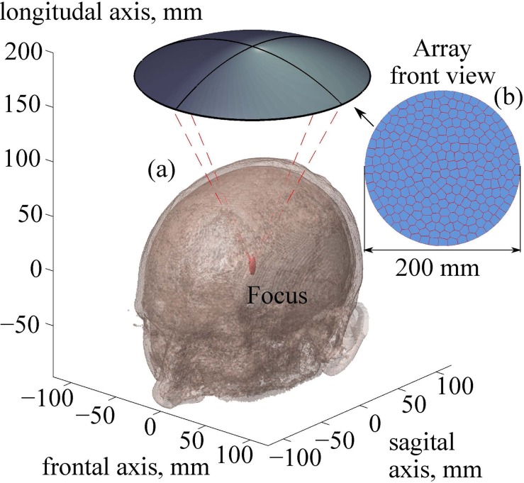
Here, a specific array with desired filling factor is designed based on the approach described in Rosnitskiy et al. (2018). The transducer contains N = 256 elements, which is a typical number for currently used multi-element HIFU arrays. Polygonal elements of equal area are distributed in a fully populated random pattern [Fig. 2(b)]. The algorithm for the distribution of the elements is based on the capacity-constrained tessellation and provides the maximum possible filling of the array surface with the elements (100% if no gaps between elements needed in practice are introduced), while ensuring their non-periodic arrangement (Balzer et al., 2009; Rosnitskiy et al., 2018). To avoid an electrical breakdown between the elements, 0.5-mm gaps between the neighboring elements are introduced. With this technological limitation, the filling factor of the array surface decreases from 100% to 92%, still having the highest achievable value for a given geometry of the transducer and the number of elements.
FIG. 2.
(Color online) (a) Geometry of the ultrasound beam from a fully populated array focused through an intact skull into the thalamus region. (b) A front view sketch of the array. Parameters of the array: number of elements, N = 256; frequency, f = 1 MHz; radius of curvature, F = 200 mm; aperture, D = 200 mm.
C. Modeling of linear propagation
In HIFU fields, effects of acoustic nonlinearity may be strongly pronounced not only in the focal region but also on the way to the focus. Therefore, in the general case, the acoustic field modeling should be performed using nonlinear algorithms, which usually require considerable computational resources. However, to perform such nonlinear modeling, it is necessary to set a boundary condition at the array elements that provides correction of aberrations introduced by the skull. This task also requires wave propagation modeling, but that problem is computationally simpler and can be solved using more economic linear algorithms. Modeling of wave propagation in the linear approximation also helps evaluating the effect of the inhomogeneities on the focusing and the quality of aberration correction. Two algorithms are considered here for the linear simulations: the Rayleigh integral method and the more complex approach, which is based on the wave equation for viscoelastic medium.
It is assumed that the region between the array surface and the top of the head is filled with a non-absorptive homogeneous coupling liquid (water; Fig. 3). In this region the modeling is based on the analytical solution provided by the Rayleigh integral for the complex acoustic pressure amplitude of each element of the array
| (1) |
with time dependence described as . Here, i is the imaginary unit, is the angular frequency of the array, is the wavenumber, is the sound speed, is the density of the medium, S is the surface area of the array element, is the complex amplitude of the normal component of the vibration velocity at the surface of the array, and is the distance from the surface element dS′ to the observation point.
FIG. 3.
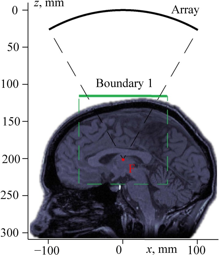
(Color online) Setting a boundary condition for modeling the propagation of a linear beam through a human head. “Array” is the surface of the transducer; boundary 1 is the plane of setting the boundary condition for pseudo-spectral time domain numerical simulation of the beam propagation through the skin, skull, and brain; and “F” is the focal point.
For the considered problem, the distance from each of the array elements to the region of interest (the vicinity of the skull) is much larger than the extent of the element's near field. Therefore, near the skull, the field of the array with the polygonal elements can be calculated with high accuracy as a sum of the analytical solutions for the far-field of each element (Ilyin et al., 2015),
| (2) |
Here and are the radius vectors of the observation point and the center of the kth array element, respectively, N is the total number of elements, is the complex amplitude of vibrational velocity at the kth element, and are the corresponding real amplitude and phase. Each element is assumed to vibrate uniformly, i.e., as a piston source. The coefficient is a known analytic function calculated using a far-field solution for a piston source in the shape of the right triangle (Rosnitskiy et al., 2018).
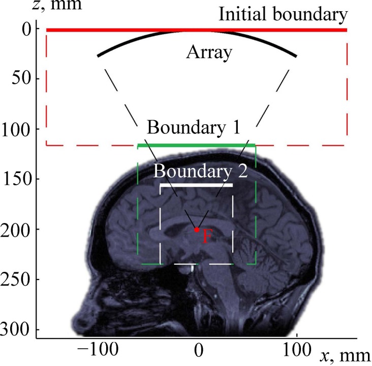
Using the described analytical method, the complex acoustic pressure amplitude was calculated in a square region of the xy-plane, denoted as boundary 1 in Fig. 3. This plane is perpendicular to the array axis and located above the head. For precise calculations, the dimensions of the simulation window were chosen 20% wider than the cone formed by rays emitted from the array edges to the focal point (Fig. 3).
The Rayleigh integral is applicable only to wave propagation in a homogeneous medium. Once the wave reaches the closest location on the skull, more sophisticated modeling has to be used. To do so, the surface region boundary 1 was used for setting a boundary condition to the next linear model, which is based on the following wave equation (Treeby and Cox, 2014a):
| (3) |
Here, and are the jth components of the particle displacement and radius vector, respectively, and are the Lame parameters, is the shear modulus, and are the compressional and shear viscosity coefficients, respectively, and the Einstein summation notation is used. Equation (3) describes acoustic wave propagation with account for the effect of viscoelasticity in accordance with the Kelvin–Voigt rheological model.
The shear modulus and Lame parameters in Eq. (3) are uniquely related to the sound speeds and of the compressional and shear waves (Table I): , . Similarly, the absorption coefficients and are related to the viscosity coefficients in the low frequency limit for power law exponent equal to 2 as and . To implement this model, the open-source k-Wave matlab Toolbox was used.2 The numerical algorithm of this software is based on the pseudo-spectral time domain method and accounts for reflection from the interfaces, generation of shear waves in the skull bones, and inhomogeneities of the sound speed, density, and absorption coefficient of the propagation medium (Treeby and Cox, 2014a; Treeby et al., 2014b). For water, skin, and brain tissues, where only compressional waves exist, the values of the shear modulus and shear viscosity were set to zero.
While the 3D numerical scheme used in the k-Wave toolbox is quite time and memory consuming, dividing the entire domain into specific subregions allows k-Wave simulations to be performed in a relatively small region only (shown by the dashed rectangular contour in Fig. 3), which can be implemented using an ordinary personal computer.
The following parameters of the computational grid were used in simulations using the k-Wave toolbox: 256 × 256 × 256 number of points in the x, y, and z directions with grid point spacing of = = = 0.5 mm. The spatial step was chosen in accordance with a convergence test performed for a smaller single-element source of the same frequency and focusing angle as the considered array. It was shown that for a twice smaller spatial grid step the simulated pressure amplitude field differs by less than 10% as compared to the maximum value. Such accuracy was considered sufficient for the aims of this study. To upsample the head model, each MRI voxel with a size of 1 × 1 × 1 mm was replaced by eight 0.5 × 0.5 × 0.5 mm sized sub-voxels by dividing it in half in each spatial direction. The sub-voxels had the same type (“water,” “skin,” “skull,” or “brain”) as the parent voxel. Then, the resulting 3D image was smoothed using the corresponding function of the k-Wave toolbox (Treeby and Cox, 2014a; Treeby et al., 2014b), which uses a 3D frequency domain filter based on the Blackman window.
A perfectly matched layer (PML) occupied 10 points around each edge of the domain, thus the actual size of the spatial grid was 236 × 236 × 236 points. The time step was based on the Courant–Friedrichs–Lewy (CFL) number of 0.1, where , and is the maximum sound speed.
D. Aberration correction
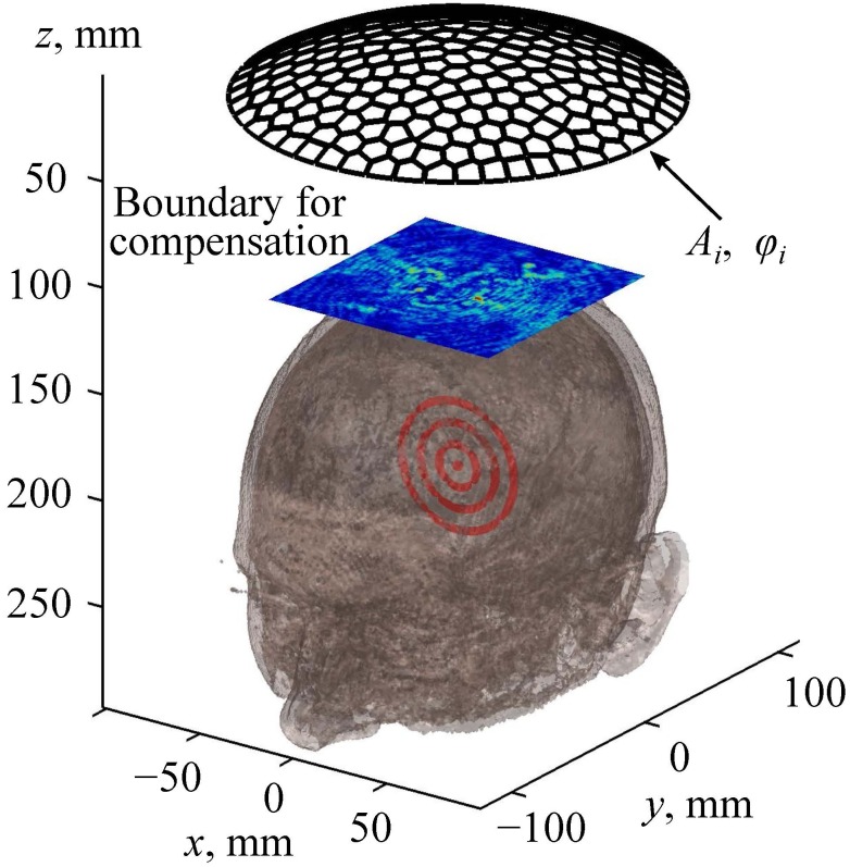
To compensate for the wavefront distortion induced by the skin, skull bones, and brain, a new method of aberration correction based on the linear propagation algorithms described above is proposed and used here. Instead of modeling ultrasound propagation from the source to the focus, as it was presented in Sec. II C, the aberration correction procedure requires solution of the inverse problem, i.e., the Rayleigh-integral and k-Wave methods now are used in the reverse order. First, propagation of the spherical viscoelastic wave was simulated emerging from the focal point and passing through the brain, skull, and skin to the plane xy region “boundary for compensation” (Fig. 4). This boundary is, in fact, the same as the boundary 1 used in Sec. II C (Fig. 3). Next, to compensate for the aberrations, complex amplitudes of the vibrational velocity at the array elements were determined that reproduce the distribution of the complex pressure amplitude in the boundary for compensation (Fig. 4). This problem was solved using the analytical method presented by Eq. (2), which is valid because the boundary for compensation region is located in water outside the head. Note that the complex amplitude distribution in the rectangular boundary for compensation is obtained numerically and thus can be represented as a discrete L × M matrix of complex numbers given at the nodes of a square spatial grid. Here L and M are numbers of the grid points in the x and y directions. This matrix can be reshaped into the vector of complex amplitudes where j = 1,2,…,L × M. Each value can be represented as an analytical solution (2) for the array field
| (4) |
where and are the radius vectors of the jth grid point in the boundary for compensation and kth array element's center, respectively, and is the complex amplitude of the vibrational velocity at the kth element, respectively. Denoting and rewriting Eq. (4) with the use of the Einstein summation notation yield a set of linear equations for the unknown
| (5) |
This set of equations (5) is overdetermined: the number of unknowns is N = 256 and the number of equations (or number of grid points in the boundary of compensation) is typically L × M > 104. An approximate solution of Eq. (5) can be found using the method of ordinary least squares (OLS) as a minimum of the function
| (6) |
where the matrices , and C represent , and , and the superscript T indicates a matrix transpose (Goldberger, 1964).
FIG. 4.
(Color online) An illustration of the method for aberration correction. Here Ai and φi are the amplitudes and phases, respectively, at the array elements.
Based on the OLS-solution of Eq. (6), the vibrational velocity amplitudes are found that would be generated in the centers of the array elements when the acoustic field is radiated by a point source in the brain. The aberration correction is then performed based on the principle of phase conjugation (or its analog in the time domain, time reversal; Zel'dovich et al., 1985; Jackson and Dowling, 1991; Fink, 1992). To do so, the array elements are excited with the conjugated phase: . As for the amplitudes at the elements, with the exact approach of the phase conjugation they should be the same as in the incident test wave from a point source. However, since the wavefront is primarily determined by the phases at the elements, it can be expected that the quality of the correction of aberrations after phase conjugation will be high even with equal amplitudes at the elements. Equalizing the amplitudes allows maximizing the power output of the array, which is beneficial for both thermal and mechanical HIFU applications.
E. Modeling of nonlinear propagation
Once the aberration corrections are introduced, nonlinear ultrasound propagation from the array through the water, skin, skull bones, and brain tissues can be simulated. Nonlinear modeling of HIFU in such extended 3D volume with account for hundreds of harmonics is a challenging problem, which, however, can be solved using appropriate assumptions.
Note that in the whole wave propagation region only a thin layer is essentially inhomogeneous, which includes the skin and skull. At the same time, the skull bones induce very strong frequency-dependent ultrasound transmission losses. Estimations based on the experimental data yield a 12 dB loss at 1 MHz with correction for aberrations, and for the frequencies higher than 1.3 MHz the transmission coefficient becomes almost negligible: loss of about 20 dB already for 1.3 MHz frequency (Marsac et al., 2017; Pinton et al., 2011). It is therefore reasonable to assume that the contribution of nonlinear effects in the skull is insignificant compared with very strong absorption and reflection. Moreover, the latter effects almost completely dampen the higher harmonics, i.e., the skin and skull serve as an acoustic low-pass filter that only passes the fundamental harmonic. If this is the case, then transmission through the skin and skull can be modeled using the k-Wave algorithm only for the first harmonic, while higher harmonics can be dropped during the transmission.
On the contrary, acoustic propagation in the water-filled region between the array and the skin, and in the brain-tissue region on the way from the skull to focus, is essentially nonlinear, resulting in strong nonlinear waveform distortion even in the near field of the array. These two regions are homogeneous (water) or contain only smooth inhomogeneities (brain), and therefore back-scattering does not play a role there, which allows employing efficient “one-way” nonlinear propagation algorithms.
To account for nonlinear effects in those two regions, the 3D Westervelt equation is used,
| (7) |
Here p is the acoustic pressure, is the retarded time, is Laplacian, and denote nonlinearity coefficient and diffusivity of sound of the medium, respectively.
For the nonlinear modeling in the water-filled region outside the head, the boundary condition is set in the plane xy at the apex of the array (“initial boundary” in Fig. 5). Details of the numerical algorithm for solving the Westervelt equation and transferring the boundary condition from the array surface to the tangent plane have been described in the earlier papers (Yuldashev and Khokhlova, 2011; Kreider et al., 2013). The values for all simulation constants in water and inside the brain are listed in Table I. The absorption coefficient is related to the diffusivity of sound as .
FIG. 5.
(Color online) Setting the boundary condition for modeling the propagation of a nonlinear beam through the human head. The array is the surface of the FPA. Boundary 1 and boundary 2 are the planes of setting the boundary condition for the Westervelt and pseudo-spectral time domain simulations, respectively, of the wave propagation through the water, skin, skull, and brain to boundary 2. Boundary 2 is the plane of setting the boundary condition for nonlinear modeling in deep brain structures using the Westervelt equation. “F” is the focal point.
At high-power outputs, when ultrasound propagates in water in the near field of the array, nonlinear effects may already be present, and therefore the acoustic beam incident on the skull may contain higher harmonics. Further modeling of the acoustic field in an inhomogeneous medium (skin, skull, and brain) is performed based on the aforementioned assumption that the skull behaves as a linear low-pass filter. With this in mind, higher harmonics are omitted (Marsac et al., 2017; Pinton et al., 2011), and the results for the first harmonic, obtained from the Westervelt equation modeling, are used to set the boundary condition in the plane boundary 1 and perform the linear k-Wave viscoelastic simulations for the beam propagation through the skull and adjacent tissues (over the distance from boundary 1 to “boundary 2”—see Fig. 5). As the first harmonic is also strongly attenuated in the skull, nonlinear effects over a short distance between the skull and boundary 2 are also neglected. Then, the acoustic pressure calculated by the k-Wave algorithm in the plane boundary 2 is used as a new boundary condition for the Westervelt-equation modeling of nonlinear propagation inside the homogeneous absorptive brain tissue (Fig. 5).
For the k-Wave part of simulation, the same grid steps and parameters of the propagation medium are used as in Sec. II C.
For the Westervelt modeling the spatial grid is ten times finer: = = 0.05 mm, from 0.05 mm to 0.1 mm. The time step is chosen as = 0.5 ns, and up to 1000 harmonics are used in the simulation depending on the level of nonlinear distortion of the waveform.
III. RESULTS
A. Acoustic model of the human head
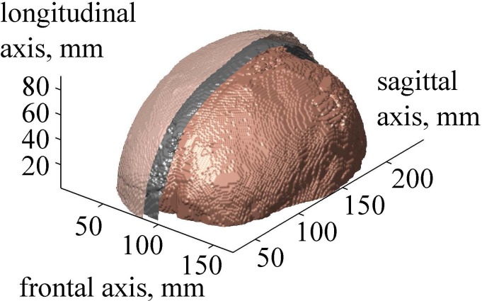
After segmentation of all two-dimensional (2D) axial slices described in Sec. II A, a 3D acoustic model of the head was obtained (Fig. 6). The developed layered model has the following thickness parameters at the top of the head close to the beam axis: skin thickness is 5 mm, including layers of epidermis, dermis, and hypodermis, and skull thickness is 6.5 mm. The center of curvature of the transducer was positioned in the thalamus region at the depth of 70 mm in the brain (Fig. 2).
FIG. 6.
(Color online) The result of 3D segmentation of the human head. Surfaces of the skin, skull, and brain are shown. Skin and skull are partially removed for visualizing the surface of the brain.
B. Linear simulation with and without aberration correction
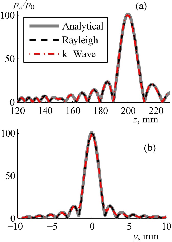
To test the accuracy of the proposed combined modeling method, the array field was calculated assuming that the acoustic parameters of skin, skull bones, and brain tissues are equal to the parameters of water. In this case of propagation entirely in water the pressure field was simulated using three independent models: fast analytical method (thick curve in Fig. 7), direct numerical calculation of the Rayleigh integral (dashed curve), and k-Wave simulation with a boundary condition set in the plane boundary 1 (dashed-dotted curve). These three solutions for the pressure amplitude normalized to the initial pressure at the array elements agree very well in both axial [Fig. 7(a)] and radial [Fig. 7(b)] directions: the maximum difference between the results is less than 1%. This test also showed that the width of the spatial window for setting the boundary condition in the plane boundary 1 was sufficient: the results of the k-Wave simulation (boundary condition in the plane boundary 1) and analytical method (boundary condition at the array surface) agree very well [Fig. 7(a)].
FIG. 7.
(Color online) Validation of the numerical algorithm for calculating the linear field generated by the array in water. Pressure amplitude distributions pA/p0 normalized to the initial pressure p0 at the array elements (a) along and (b) transverse the array axis in the focal plane. “Analytical” denotes the use of the analytical method for simulating the array field within the far-field approximation of each element, “Rayleigh” is the direct calculation of the Rayleigh integral, and “k-Wave” is the pseudo-spectral time domain simulation from boundary 1 (Fig. 4).
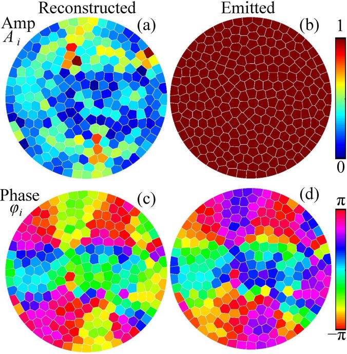
After verifying the linear simulation method in water, the amplitudes and phases at the elements of the proposed array were chosen to correct for the aberrations when propagation through the skull. The solution [Eq. (6)] to the system [Eq. (5)] is presented in Figs. 8(a) and 8(c) for the amplitudes and phases of the reconstructed complex vibrational velocity amplitudes at the elements of the array, k = 1,…,256. It is seen that the distribution of the amplitude is non-uniform. However, the shape of the wavefront is mostly determined by the phases, while the amplitude values affect the magnitude of the focal pressure. Thus, for the emitted field all the amplitudes at the array elements were set to the same maximum value [Fig. 8(b)] while the phases were inverted, [Fig. 8(d)]. This approach of keeping the same amplitude at the elements is used clinically to reach the maximum intensity at the focus.
FIG. 8.
(Color online) Distributions of the (a) vibrational velocity amplitudes Ai and (c) phases φi at the elements of the array that provide the best reconstruction of the complex pressure amplitude at the boundary of compensation. The boundary condition to the modeling is set by choosing the uniform amplitude (b) and inverted phase (d) distributions at the array elements.
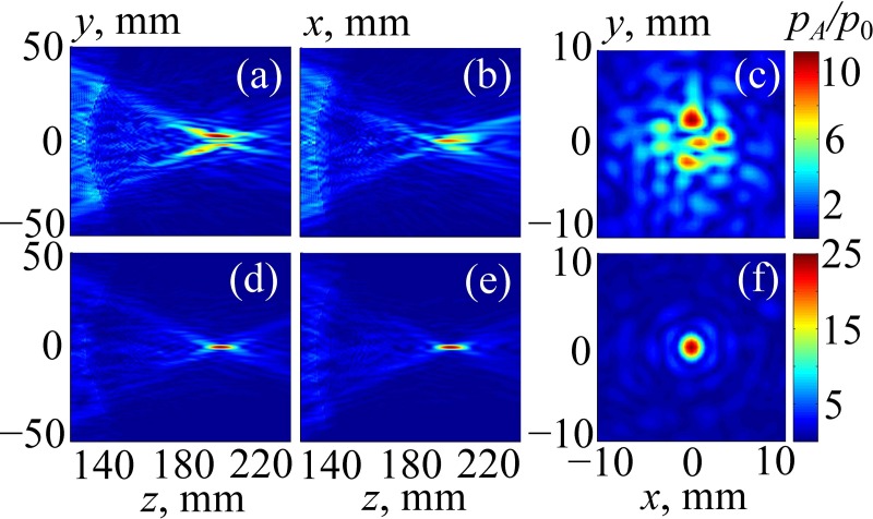
Figure 9 illustrates the results of simulating the linear beam propagation through the human head without Figs. 9(a)–9(c) and with Figs. 9(d)–9(f) aberration correction. First, no phase delays were introduced, and the array field was calculated using the method from Sec. II C. Then, aberration compensation was performed as described in Sec. II D, and the calculations were performed again. Pressure amplitude distributions, , normalized to the initial pressure at the array elements are presented: Figs. 9(a) and 9(d), in the sagittal plane zy (x = 0); Figs. 9(b) and 9(e), in the frontal plane zx (y = 0); and Figs. 9(c) and 9(f), in the transverse plane xy passing through the focal point. The geometry of the sagittal plane zy is shown in Fig. 3 by dashed lines.
FIG. 9.
(Color online) Linearly simulated 2D distributions of the pressure amplitude inside the human head in (a),(d) the sagittal plane zy; (b),(e) the frontal plane zx; and (c),(f) the transverse plane passing through the focal point. Results are normalized to the pressure amplitude p0 at the array elements. In (a)–(c) the results are obtained without aberration correction, and in (d)–(f) the results are obtained with aberration correction.
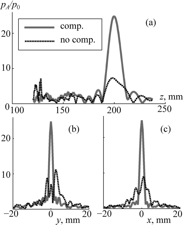
The field pattern for sonication without aberration correction is strongly distorted: the main focal lobe is split into several parts, and the side field maxima appear near the skull. The maximum pressure in the field is shifted from the center of curvature of the array, its normalized amplitude is 12, and the amplitude of the focal pressure is 7 [Figs. 9(a)–9(c)]. The level of the side lobes (the maximum absolute value of the acoustic pressure amplitude out of the focal region) is about = 7, which is equal to the focal pressure.
After aberration correction, the field pattern is improved significantly: the main focal lobe is tight, and the level of side maxima is relatively low [Figs. 9(d)–9(f)]: = 3 as compared to focal pressure amplitude = 25. A more detailed comparison of these two cases is shown in Fig. 10. Again, after corrections were done (solid curve), the maximum pressure amplitude at the focus is at least four times higher than without aberration correction. Furthermore, significant decrease of the side maxima near the skull is evident: is four times lower than without correction [Fig. 10(a)].
FIG. 10.
Linear simulation of the pressure amplitude inside the human head (a) along the array axis and (b),(c) transverse the axis in the focal plane. Distributions pA/p0 are normalized to the initial pressure p0 at the array elements. “comp.” and “no comp.” are the results obtained with and without compensation for aberrations.
C. Nonlinear simulation with aberration correction
The results of nonlinear modeling of the beam focusing performed in three steps as described in Sec. II E (Fig. 5) are presented here. Initial phase delays at the array elements for aberration correction were introduced using linear modeling [Figs. 8(b) and 8(d)].
Then, at the first step, nonlinear simulations performed in water using the Westervelt model (Fig. 5 from initial boundary to boundary 1) showed that for the maximum initial intensity, = 40 W/cm2, the peak positive and peak negative pressures at the array axis did not exceed 3.5 MPa and −3.3 MPa, correspondingly. In terms of the power distribution between harmonics, an estimate based on the angular spectrum method (Sapozhnikov and Bailey, 2013) showed that 22% of the initial total acoustical power was transferred from the first harmonic into higher harmonics. Despite the presence of nonlinear distortion of the pressure waveforms in water near the head (the maximum amplitude of the second harmonics is 40% as compared to the first harmonic), such peak-rarefactional pressure is close to the diagnostic level and is below the cavitation threshold of about −8 MPa that was found to cause mechanical tissue disruption in recent drug delivery studies (Nightingale et al., 2015; Li et al., 2015). For other positions of the focus, as well as a more complex model of a heterogeneous skull, further investigation is needed to verify the safety of the treatment.
At the second step, linear viscoelastic k-Wave simulations were performed for propagation through the skin, skull, and brain tissues from boundary 1 to boundary 2 (Fig. 5, Sec. II E). At the third step, for propagation from boundary 2 to the focus (Fig. 5), the results were obtained for both the linearized () and nonlinear () Westervelt equation (7).
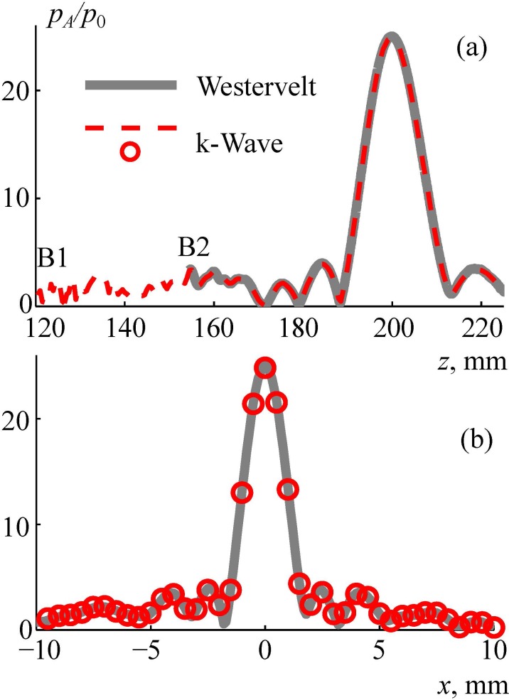
The linearized Westervelt equation was considered for comparison with the linear k-Wave equation (3) to validate the simulation method. The results of validation are shown in Fig. 11. The axial [Fig. 11(a)] and radial [Fig. 11(b)] distributions of the pressure amplitude , normalized to the initial pressure at the array elements, are compared for the two models. The dashed curves and circles represent a k-Wave solution with the boundary condition set in the plane boundary 1, and the thick line represents the solution of the linearized Westervelt model with the boundary condition set in the plane boundary 2. A good agreement between the models is demonstrated. After validation, the third step of simulations was performed inside the brain based on the nonlinear Westervelt equation (Sec. II E). Three values of the initial intensity at the array elements were chosen: 30 W/cm2, 35 W/cm2, and 40 W/cm2 (the latter is considered as a characteristic technological maximum; Cathignol, 2002; Rosnitskiy et al., 2018).
FIG. 11.
(Color online) Comparison of numerical algorithms for calculating the linear ultrasound field generated by the array inside the human head. Pressure amplitude distributions pA/p0 normalized to the initial pressure at the array element p0 (a) along and (b) transverse the array axis. “Westervelt” is the linearized Westervelt numerical model with boundary condition set at boundary 2, k-Wave is the numerical pseudo-spectral time domain simulation with boundary condition set at boundary 1.
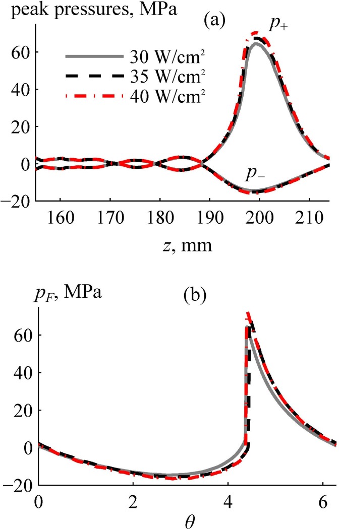
Figure 12 shows the results of nonlinear modeling inside the brain for three different values of the initial intensities at the array elements: solid line, 30 W/cm2; dashed line, 35 W/cm2; dashed-dotted line, 40 W/cm2. Figure 12(a) depicts the peak positive and negative pressures along the beam axis z. There is a strong asymmetry in peak pressures: peak positive pressures are 4–5 times higher than the peak negative pressures.
FIG. 12.
(Color online) Results of nonlinear simulation of the ultrasound pressure field inside the human head. (a) Axial distributions of the peak positive and negative pressures for different initial intensities at the array elements. (b) One cycle of the focal waveforms pF(θ) simulated for given initial intensities. Here, θ is the dimensionless time.
Figure 12(b) shows the pressure waveforms at the focus, where is the dimensionless retarded time. The waveforms contain shocks with amplitudes greater than 60 MPa. The shock amplitudes for the cases of the initial intensities at the array elements of 30 W/cm2, 35 W/cm2, 40 W/cm2 are 60 MPa, 65 MPa, and 71 MPa, respectively, from which the one of 65 MPa represents a developed shock. The definition of the developed shock has been introduced in our earlier publications to serve as a metric for characteristic shock amplitude that can be reached at the focus of a transducer with certain focusing angle (Rosnitskiy et al., 2017b). It can be determined visually by the coincidence of its lower boundary with the zero-pressure level. These shock amplitudes are applicable for mechanical tissue disintegration using the BH method (Khokhlova et al., 2015). Peak pressure values outside the main focal lobe [Fig. 12(a)] did not exceed 5 MPa.
IV. DISCUSSION AND CONCLUSIONS
In this paper, a novel approach for trans-skull HIFU focusing deep inside the brain is proposed as an alternative to the existing clinically used one. The approach is aimed for achieving shock-forming conditions at the focus by using a new design of fully populated random phased arrays with a smaller focusing angle and higher frequency.
The main features of the considered approach include the specific design of the ultrasound array with proper correction for aberrations caused by the skull. It is proposed to use a fully populated 256-element array in the form of a spherical segment with a diameter and radius of curvature of 200 mm. This array is more compact than the existing ExAblate arrays (InSightec Ltd., Tirat Carmel, Israel), which have the shape of 300 mm-diameter hemispheres. The use of such less focused array with an F# close to 1 would allow expanding the HIFU treatment volume by mechanically moving the array to or from the skull and turning it relative to the patient's head. Another advantage of such a compact array as compared to the existing hemispherical arrays is elongation of the focal region, which facilitates formation of shocks at the focus.
A novel method of creating a fully populated random pattern of the elements (filling factor 92% taking into account 0.5 mm spacing between the elements) was used to provide the highest possible focal intensity for a given transducer geometry and diminish formation of side lobes with electronic focus steering related to the regular element distributions (Rosnitskiy et al., 2018). The proposed array configuration opens ways for further modifications and improvements. Higher shock amplitudes can be achieved at the focus by increasing the focusing angle of the array. In addition, decreasing the focal length of the array can help to reduce nonlinear effects near the skull (Rosnitskiy et al., 2017b). Note that the number of elements in the proposed array is four times lower as compared to the existing 1024-element ExAblate arrays. This simplifies the construction and reduces the price of the driving system but still provides good aberration correction. However, the number of elements can be increased to expand focus steering and aberration correction capabilities.
The proposed approach was implemented in simulations using a specific 3D acoustic model of a human head. The model was created using segmentation of MRI images of the human head taken from an open database. The head was partitioned into four segments (skin, skull, brain, and outer space filled with water). All segments were considered homogeneous. In further studies, the proposed segmentation algorithm can be improved by using high-resolution MR or CT images for reconstructing acoustic properties of the head taking into account small scale inhomogeneities of the skull.
To demonstrate the feasibility of realizing shock-forming conditions when focusing through the skin, skull, and brain tissues, 3D ultrasound beam simulations were performed. None of the existing algorithms for simulating ultrasound propagation through the skull can be directly applied for the considered case of strongly nonlinear focusing when hundreds of harmonics are generated and shocks are formed. To overcome this challenge, a multi-model numerical algorithm was developed to perform the simulation. It combines different physical models that are the most suitable and allow fast calculations of the wave propagation in the regions with different acoustic properties. The proposed approach allows for accounting for the effects of absorption, reflections, inhomogeneities in a form of layered tissues, shock formation, and generation of shear waves in the skull bones. The algorithm was implemented on an ordinary personal computer (Intel Core i7–6700 K, 4 cores, 3.4 GHz, 32 GB RAM, Intel Corporation, Santa Clara, CA).
An important feature of the proposed approach is the numerical procedure developed for the aberration correction. This method of aberration correction, similar to that previously considered in publications describing transcranial HIFU, is based on the phase conjugation method: simulating the field of a spherical wave diverging from the focal point to the plane surface outside the head (Hynynen et al., 1998; Fink, 1992). In the current study the phase conjugation technique was not applied in a direct way; instead, a system of linear equations in the matrix form was solved to find complex vibrational velocity amplitudes at the array elements that can reconstruct the field in the plane surface. The first part of the method allows for accounting the effects of inhomogeneities inside the head and generating shear waves in the skull bone. The second mathematical part uses the OLS method to obtain an analytical solution for optimal phase delays at the elements. This approach provided tight focusing and significant improvement of the field pattern. Note that the method proposed in this study differs from conventional time reversal approach when a spherical acoustic wave propagates from the geometrical center of the multi-element array to the array elements (Thomas and Fink, 1996; Fink, 1992, 1997; Marsac et al., 2017). In contrast, the approach developed here first simulates a spherical wave from the focal point to the plane outside the head and then uses analytical relation [Eq. (5)] in water to find complex amplitudes at the array elements directly. This allows avoiding numerical errors, related to the discrete computational grid and the vibrational velocity phase oscillations at the array elements.
Linear simulations with aberration correction demonstrated that the focal pressure inside the brain is 12 dB lower than when focusing in water [ = 25 vs 100; see Figs. 7(a) and 10(a)]. The simulation results are consistent with the experiment performed in (Marsac et al., 2017). This experiment showed a −12 dB attenuation in the skull for 1 MHz with aberration correction. Taking into account a 0.21 dB/cm absorption inside the brain at a depth of 7 cm, the total attenuation is −13.4 dB, which in order of magnitude corresponds to a loss of −12 dB obtained from the simulation.
An important simulation result is that the designed array can generate nonlinear waveforms at the focus with shock amplitudes >60 MPa for the initial intensity at the array elements of 30 W/cm2, which is 25% smaller than the typical technological maximum for operating the array (40 W/cm2). These shock amplitudes are sufficient to produce enhanced heating and mechanical tissue ablation using the mechanism of boiling histotripsy (Khokhlova et al., 2015). Concerning the safety of the proposed approach, the simulations showed that the peak positive and peak negative pressures near the skull did not exceed 3.5 MPa and −3.3 MPa at the highest power level of the array. While mechanical effects of cavitation at these levels should be evaluated in experiments, recent data showed that tissue permeabilization necessary for drug delivery was achieved with ms-long pulses at much higher pressure levels of 8–9 MPa (Li et al., 2015). Even for diagnostic purposes, feasibility of using ms-long pulses with mechanical index ∼ 4 has been discussed (Nightingale et al., 2015). In addition, reduction in the initial intensity and peak pressures near the skull could be achieved by the slight increase of frequency and augmenting the focusing angle (Rosnitskiy et al., 2017b).
In conclusion, a new array design for nonlinear trans-skull exposures in brain is proposed. Feasibility of achieving shock-forming conditions at the focus sufficient for enhancement of thermal and boiling histotripsy in the brain was demonstrated in simulations. The proposed array design has a potential for enlarging the capabilities of transcranial ultrasound surgery.
ACKNOWLEDGMENTS
This study was supported by the National Institutes of Health (NIH) Grant Nos. EB007643 and EB025187, RFBR Grant No. 19-02-00035, Ph.D. student stipend from “Basis” Foundation No. 17-21-114-1, and the stipend of the President of Russia SP-2644.2018.4. The part on developing the aberration correction algorithm was supported by the Russian Science Foundation (RSF) Grant No. 19-12-00148. The authors are very grateful to Professor J. Hand for productive discussion of the obtained results and editorial comments and Dr. B. Treeby for detailed answers to our questions about the k-Wave toolbox.
Footnotes
See https://wiki.idoimaging.com (Last viewed 13 September 2019).
See http://www.k-wave.org (Last viewed 13 September 2019).
References
- 1. Aubry, J.-F. , Tanter, M. , Pernot, M. , Thomas, J.-L. , and Fink, M. (2003). “ Experimental demonstration of non invasive transskull adaptive focusing based on prior CT scans,” J. Acoust. Soc. Am. 113, 84–93. 10.1121/1.1529663 [DOI] [PubMed] [Google Scholar]
- 2. Balzer, M. , Schlömer, T. , and Deussen, O. (2009). “ Capacity-constrained point distributions: A variant of Lloyd's method,” ACM Trans. Graph. 28(3), article 86, 1–8. 10.1145/1531326.1531392 [DOI] [Google Scholar]
- 3. Cathignol, D. (2002). “ High intensity piezoelectric sources for medical applications: Technical aspects,” in Nonlinear Acoustics at the Beginning of the 21st Century ( Faculty of Physics, Moscow State University, Moscow, Russia: ), pp. 371–378. [Google Scholar]
- 4. Chauvet, D. , Marsac, L. , Pernot, M. , Boch, A. L. , Guillevin, R. , Salameh, N. , Souris, L. , Darrasse, L. , Fink, M. , Tanter, M. , and Aubry, J. F. (2013). “ Targeting accuracy of transcranial magnetic resonance-guided high-intensity focused ultrasound brain therapy: A fresh cadaver model,” J. Neurosurg. 118(5), 1046–1052. 10.3171/2013.1.JNS12559 [DOI] [PubMed] [Google Scholar]
- 5. Clement, G. T. , and Hynynen, K. (2002). “ A non-invasive method for focusing ultrasound through the human skull,” Phys. Med. Biol. 47(8), 1219–1236. 10.1088/0031-9155/47/8/301 [DOI] [PubMed] [Google Scholar]
- 6. Duck, F. A. (1990). Physical Properties of Tissue: A Comprehensive Reference Book ( Academic, London, 346 pp. [Google Scholar]
- 7. Elias, W. J. , Huss, D. , Voss, T. , Loomba, J. , Khaled, M. , Zadicario, E. , Frysinger, R. C. , Sperling, S. A. , Wylie, S. , Monteith, S. J. , Druzgalm, J. , Shahm, B. B. , Harrison, M. , and Wintermark, M. (2013). “ A pilot study of focused ultrasound thalamotomy for essential tremor,” N. Engl. J. Med. 369(7), 640–648. 10.1056/NEJMoa1300962 [DOI] [PubMed] [Google Scholar]
- 8. Fink, M. (1992). “ Time reversal of ultrasonic fields—Part I: Basic principles,” IEEE Trans. Ultrason. Ferroelect. Freq. Control 39(5), 555–566. 10.1109/58.156174 [DOI] [PubMed] [Google Scholar]
- 9. Fink, M. (1997). “ Time reversed acoustics,” Phys. Today 50(3), 34–40. 10.1063/1.881692 [DOI] [Google Scholar]
- 10. Gavrilov, L. R. , and Hand, J. W. (2000). “ A theoretical assessment of the relative performance of spherical phased arrays for ultrasound surgery,” IEEE Trans. Ultrason. Ferroelect. Freq. Control 47(1), 125–139. 10.1109/58.818755 [DOI] [PubMed] [Google Scholar]
- 11. Gavrilov, L. R. , and Hand, J. W. (2014). High-Power Ultrasound Phased Arrays for Medical Applications ( Nova Science, Hauppauge, NY: ), 200 pp. [Google Scholar]
- 12. Gavrilov, L. R. , Sapozhnikov, O. A. , and Khokhlova, V. A. (2015). “ Spiral arrangement of elements of two-dimensional ultrasonic therapeutic arrays as a way of increasing the intensity at the focus,” Bull. Russ. Acad. Sci. Phys. 79(10), 1232–1237. 10.3103/S106287381510010X [DOI] [Google Scholar]
- 13. Goldberger, A. S. (1964). “ Classical linear regression,” in Econometric Theory ( Wiley, New York: ), pp. 156–212. [Google Scholar]
- 14. Goss, S. A. , Frizzell, L. A. , and Dunn, F. (1979). “ Ultrasonic absorption and attenuation in mammalian tissues,” Ultrasound Med. Biol. 5(2), 181–186. 10.1016/0301-5629(79)90086-3 [DOI] [PubMed] [Google Scholar]
- 15. Hand, J. W. , Shaw, A. , Sadhoo, N. , Rajagopal, S. , Dickinson, R. J. , and Gavrilov, L. R. (2009). “ A random phased array device for delivery of high intensity focused ultrasound,” Phys. Med. Biol. 54(19), 5675–5693. 10.1088/0031-9155/54/19/002 [DOI] [PubMed] [Google Scholar]
- 16. Hynynen, K. , and Jolesz, F. A. (1998). “ Demonstration of potential noninvasive ultrasound brain therapy through an intact skull,” Ultrasound Med. Biol. 24(2), 275–283. 10.1016/S0301-5629(97)00269-X [DOI] [PubMed] [Google Scholar]
- 17. Hynynen, K. , and Jones, R. M. (2016). “ Image-guided ultrasound phased arrays are a disruptive technology for non-invasive therapy,” Phys. Med. Biol. 61, 206–248. 10.1088/0031-9155/61/17/R206 [DOI] [PMC free article] [PubMed] [Google Scholar]
- 18. Hynynen, K. , and Sun, J. (1999). “ Trans-skull ultrasound therapy: The feasibility of using image-derived skull thickness information to correct the phase distortion,” IEEE Trans. Ultrason. Ferroelectr. Freq. Control 46(3), 752–755. 10.1109/58.764862 [DOI] [PubMed] [Google Scholar]
- 19.IEC (2007). TS 61949, Ultrasonics—Field Characterization—In Situ Exposure Estimation in Finite-Amplitude Ultrasonic Beams ( International Electrotechnical Commission, Geneva, Switzerland: ). [Google Scholar]
- 20. Ilyin, S. A. , Yuldashev, P. V. , Khokhlova, V. A. , Gavrilov, L. R. , Rosnitskiy, P. B. , and Sapozhnikov, O. A. (2015). “ Analytical method for evaluating the quality of acoustic fields radiated by a multielement therapeutic array with electronic focus steering,” Acoust. Phys. 61(1), 52–59. 10.1134/S1063771015010042 [DOI] [Google Scholar]
- 21. Jackson, D. R. , and Dowling, D. R. (1991). “ Phase conjugation in underwater acoustics,” J. Acoust. Soc. Am. 89(1), 171–181. 10.1121/1.400496 [DOI] [Google Scholar]
- 22. Jaros, J. , Rendell, A. P. , and Treeby, B. E. (2016). “ Full-wave nonlinear ultrasound simulation on distributed clusters with applications in high-intensity focused ultrasound,” Int. J. High Perform. C. 30(2), 137–155. 10.1177/1094342015581024 [DOI] [Google Scholar]
- 23. Jeanmonod, D. , Werner, B. , Morel, A. , Michels, L. , Zadicario, E. , Schiff, G. , and Martin, E. (2012). “ Transcranial magnetic resonance imaging–guided focused ultrasound: Noninvasive central lateral thalamotomy for chronic neuropathic pain,” Neurosurg. Focus. 32(1), E1. 10.3171/2011.10.FOCUS11248 [DOI] [PubMed] [Google Scholar]
- 24. Jing, Y. , Wang, T. , and Clement, G. T. (2012). “ A k-space method for moderately nonlinear wave propagation,” IEEE Trans. Ultrason. Ferroelect. Freq. Control 59(8), 1664–1673. 10.1109/TUFFC.2012.2372 [DOI] [PMC free article] [PubMed] [Google Scholar]
- 25. Khokhlova, T. D. , Canney, M. S. , Khokhlova, V. A. , Sapozhnikov, O. A. , Crum, L. A. , and Bailey, M. R. (2011). “ Controlled tissue emulsification produced by high intensity focused ultrasound shock waves and millisecond boiling,” J. Acoust. Soc. Am. 130(5), 3498–3510. 10.1121/1.3626152 [DOI] [PMC free article] [PubMed] [Google Scholar]
- 26. Khokhlova, V. A. , Fowlkes, J. B. , Roberts, W. W. , Schade, G. R. , Xu, Z. , Khokhlova, T. D. , Hall, T. L. , Maxwell, A. D. , Wang, Y. N. , and Cain, C. A. (2015). “ Histotripsy methods in mechanical disintegration of tissue: Towards clinical applications,” Int. J. Hyperthermia 31(2), 145–162. 10.3109/02656736.2015.1007538 [DOI] [PMC free article] [PubMed] [Google Scholar]
- 27. Khokhlova, V. A. , Yuldashev, P. V. , Rosnitskiy, P. B. , Maxwell, A. D. , Kreider, W. , Bailey, M. R. , and Sapozhnikov, O. A. (2016). “ Design of HIFU transducers to generate specific nonlinear ultrasound fields,” Phys. Procedia 87, 132–138. 10.1016/j.phpro.2016.12.020 [DOI] [PMC free article] [PubMed] [Google Scholar]
- 28. Kim, Y. , Hall, T. L. , Xu, Z. , and Cain, C. A. (2014). “ Transcranial histotripsy therapy: A feasibility study,” IEEE Trans. Ultrason. Ferroelectr. Freq. Control 61(4), 582–593. 10.1109/TUFFC.2014.2947 [DOI] [Google Scholar]
- 29. Kreider, W. , Yuldashev, P. V. , Sapozhnikov, O. A. , Farr, N. , Partanen, A. , Bailey, M. R. , and Khokhlova, V. A. (2013). “ Characterization of a multi-element clinical HIFU system using acoustic holography and nonlinear modeling,” IEEE Trans. Ultrason. Ferroelectr. Freq. Control 60(8), 1683–1698. 10.1109/TUFFC.2013.2750 [DOI] [PMC free article] [PubMed] [Google Scholar]
- 30. Li, T. , Wang, Y. N. , Khokhlova, T. D. , D'Andrea, S. , Starr, F. , Chen, H. , McCune, J. S. , Risler, L. J. , Mashadi-Hossein, A. , Hingorani, S. R. , Chang, A. , and Hwang, J. H. (2015). “ Pulsed high intensity focused ultrasound (pHIFU) enhances delivery of doxorubicin in a preclinical model of pancreatic cancer,” Cancer Res. 75(18), 3738–3746. 10.1158/0008-5472.CAN-15-0296 [DOI] [PMC free article] [PubMed] [Google Scholar]
- 31. Looi, T. , Khokhlova, V. A. , Mougenot, C. , Hynynen, K. , and Drake, J. (2016). “ In vivo feasibility study of boiling histotripsy with clinical Sonalleve system in a neurological porcine model,” in Program Booklet of the 16th Int. Symp. Therapeutic Ultrasound, Tel Aviv, Israel (March 14–16), pp. 64–66. [Google Scholar]
- 32. Marsac, L. , Chauvet, D. , La Greca, R. , Boch, A. L. , Chaumoitre, K. , Tanter, M. , and Aubry, J. F. (2017). “ Ex vivo optimisation of a heterogeneous speed of sound model of the human skull for non-invasive transcranial focused ultrasound at 1 MHz,” Int. J. Hyperthermia 33(6), 635–645. 10.1080/02656736.2017.1295322 [DOI] [PubMed] [Google Scholar]
- 33. McDannold, N. , Clement, G. , Black, P. , Jolesz, F. , and Hynynen, K. (2010). “ Transcranial MRI-guided focused ultrasound surgery of brain tumors: Initial findings in three patients,” Neurosurgery 66(2), 323–332. 10.1227/01.NEU.0000360379.95800.2F [DOI] [PMC free article] [PubMed] [Google Scholar]
- 34. Monteith, S. , Medel, R. , Kassell, N. F. , Wintermark, W. , Eames, M. , Snell, J. , Zadicario, E. , Grinfeld, J. , Sheehan, J. P. , and Elias, W. J. (2013). “ Transcranial magnetic resonance-guided focused ultrasound surgery for trigeminal neuralgia: A cadaveric and laboratory feasibility study,” J. Neurosurg. 118(2), 319–328. 10.3171/2012.10.JNS12186 [DOI] [PubMed] [Google Scholar]
- 35. Morrison, K. P. , Keilman, G. W. , and Kaczkowski, P. J. (2014). “ Single Archimedean spiral close packed phased array HIFU,” in 2014 IEEE International Ultrasonics Symposium, pp. 400–404. [Google Scholar]
- 36. Nightingale, K. R. , Church, C. C. , Harris, G. , Wear, K. A. , Bailey, M. R. , Carson, P. L. , Jiang, H. , Sandstrom, K. L. , Szabo, T. L. , and Ziskin, M. C. (2015). “ Conditionally increased acoustic pressures in nonfetal diagnostic ultrasound examinations without contrast agents: A preliminary assessment,” J. Ultrasound Med. 34(7), 1–41. 10.7863/ultra.34.7.15.13.0001 [DOI] [PMC free article] [PubMed] [Google Scholar]
- 37. Pernot, M. , Aubry, J.-F. , Tanter, M. , Thomas, J.-L. , and Fink, M. (2003). “ High power transcranial beam steering for ultrasonic brain therapy,” Phys. Med. Biol. 48(16), 2577–2589. 10.1088/0031-9155/48/16/301 [DOI] [PMC free article] [PubMed] [Google Scholar]
- 38. Pinton, G. , Aubry, J.-F. , Fink, M. , and Tanter, M. (2011). “ Effects of nonlinear ultrasound propagation on high intensity brain therapy,” Med. Phys. 38(3), 1207–1216. 10.1118/1.3531553 [DOI] [PubMed] [Google Scholar]
- 39. Pinton, G. , Aubry, J.-F. , and Tanter, M. (2012). “ Direct phase projection and transcranial focusing of ultrasound for brain therapy,” IEEE Trans. Ultrason. Ferroelectr. Freq. Control 59(6), 1149–1159. 10.1109/TUFFC.2012.2305 [DOI] [PubMed] [Google Scholar]
- 40. Raju, B. I. , Hall, C. S. , and Seip, R. (2011). “ Ultrasound therapy transducers with space-filling non-periodic arrays,” IEEE Trans. Ultrason. Ferroelect. Freq. Control 58(5), 944–954. 10.1109/TUFFC.2011.1895 [DOI] [PubMed] [Google Scholar]
- 41. Ramaekers, P. , de Greef, M. , Berriet, R. , Moonen, C. T. W. , and Ries, M. (2017a). “ Evaluation of a novel therapeutic focused ultrasound transducer based on Fermat's spiral,” Phys. Med. Biol. 62(12), 5021–5045. 10.1088/1361-6560/aa716c [DOI] [PubMed] [Google Scholar]
- 42. Ramaekers, P. , Ries, M. , Moonen, C. T. W. , and de Greef, M. (2017b). “ Improved intercostal HIFU ablation using a phased array transducer based on Fermat's spiral and Voronoi tessellation: A numerical evaluation,” Med. Phys. 44(3), 1071–1088. 10.1002/mp.12082 [DOI] [PubMed] [Google Scholar]
- 43. Rosnitskiy, P. B. , Gavrilov, L. R. , Yuldashev, P. B. , Sapozhnikov, O. A. , and Khokhlova, V. A. (2017a). “ On the possibility of using multi-element phased arrays for shock-wave action on deep brain structures,” Acoust. Phys. 63(5), 531–541. 10.1134/S1063771017050104 [DOI] [Google Scholar]
- 44. Rosnitskiy, P. , Vysokanov, B. , Sapozhnikov, O. , Gavrilov, L. , and Khokhlova, V. (2018). “ Method for designing multi-element fully populated random phased arrays for ultrasound surgery applications,” IEEE Trans. Ultrason. Ferroelectr. Freq. Control 65(4), 630–637. 10.1109/TUFFC.2018.2800160 [DOI] [PMC free article] [PubMed] [Google Scholar]
- 45. Rosnitskiy, P. B. , Yuldashev, P. V. , Sapozhnikov, O. A. , Maxwell, A. D. , Kreider, W. , Bailey, M. R. , and Khokhlova, V. A. (2017b). “ Design of HIFU transducers for generating specified nonlinear ultrasound fields,” IEEE Trans. Ultrason., Ferroelectr. Freq. Control 64(2), 374–390. 10.1109/TUFFC.2016.2619913 [DOI] [PMC free article] [PubMed] [Google Scholar]
- 46. Sapozhnikov, O. A. , and Bailey, M. R. (2013). “ Radiation force of an arbitrary acoustic beam on an elastic sphere in a fluid,” J. Acoust. Soc. Am. 133(2), 661–676. 10.1121/1.4773924 [DOI] [PMC free article] [PubMed] [Google Scholar]
- 47. Sapozhnikov, O. A. , Rosnitskiy, P. B. , and Khokhlova, V. A. (2016). “ Evaluation of nonlinear effects at the focus of a hemispherical acoustic source,” J. Acoust. Soc. Am. 140(4), 3435. 10.1121/1.4971068 [DOI] [Google Scholar]
- 48. Stephens, D. N. , Kruse, D. E. , Qin, S. , and Ferrara, K. W. (2011). “ Design aspects of focal beams from high-intensity arrays,” IEEE Trans. Ultrason. Ferroelectr. Freq. Control 58(8), 1590–1602. 10.1109/TUFFC.2011.1986 [DOI] [PMC free article] [PubMed] [Google Scholar]
- 49. Sukovich, J. R. , Cain, C. A. , Pandey, A. S. , Chaudhary, N. , Camelo-Piragua, S. , Allen, S. P. , Hall, T. L. , Snell, J. , Xu, Z. , Cannata, J. M. , Teofilovic, D. , Bertolina, J. A. , Kassell, N. , and Xu, Z. (2018). “ In vivo histotripsy brain treatment,” J. Neurosurg. (published online). 10.3171/2018.4.JNS172652 [DOI] [PMC free article] [PubMed] [Google Scholar]
- 50. Tanter, M. , Thomas, J.-L. , and Fink, M. A. (1998). “ Focusing and steering through absorbing and aberrating layers: Application to ultrasonic propagation through the skull,” J. Acoust. Soc. Am. 103(3), 2403–2410. 10.1121/1.422759 [DOI] [PubMed] [Google Scholar]
- 51. Thomas, J.-L. , and Fink, M. A. (1996). “ Ultrasonic beam focusing through tissue inhomogeneities with a time reversal mirror: Application to transskull therapy,” IEEE Trans. Ultrason. Ferroelectr. Freq. Control 43(6), 1122–1129. 10.1109/58.542055 [DOI] [Google Scholar]
- 52. Treeby, B. E. , and Cox, B. T. (2014a). “ Modeling power law absorption and dispersion in viscoelastic solids using a split-field and the fractional Laplacian,” J. Acoust. Soc. Am. 136(4), 1499–1510. 10.1121/1.4894790 [DOI] [PubMed] [Google Scholar]
- 53. Treeby, B. E. , Jaros, J. , Rohrbach, D. , and Cox, B. T. (2014b). “ Modelling elastic wave propagation using the k-Wave MATLAB toolbox,” in 2014 IEEE International Ultrasonics Symposium, pp. 146–149. [Google Scholar]
- 54. Van Dongen, K. W. , and Verweij, M. D. (2008). “ Sensitivity study of the acoustic nonlinearity parameter for measuring temperatures during high intensity focused ultrasound treatment,” J. Acoust. Soc. Am. 123(5), 3225. 10.1121/1.2933437 [DOI] [Google Scholar]
- 55. Vyas, U. , and Christensen, D. (2012). “ Ultrasound beam simulations in inhomogeneous tissue geometries using the hybrid angular spectrum method,” IEEE Trans. Ultrason. Ferroelect. Freq. Control 59(6), 1093–1100. 10.1109/TUFFC.2012.2300 [DOI] [PubMed] [Google Scholar]
- 56. White, P. J. , Clement, G. T. , and Hynynen, K. (2006). “ Longitudinal and shear mode ultrasound propagation in human skull bone,” Ultrasound Med. Biol. 32(7), 1085–1096. 10.1016/j.ultrasmedbio.2006.03.015 [DOI] [PMC free article] [PubMed] [Google Scholar]
- 57. Yuldashev, P. V. , and Khokhlova, V. A. (2011). “ Simulation of three-dimensional nonlinear fields of ultrasound therapeutic arrays,” Acoust. Phys. 57(3), 334–343. 10.1134/S1063771011030213 [DOI] [PMC free article] [PubMed] [Google Scholar]
- 58. Zel'dovich, B. Y. , Pilipetsky, N. F. , and Shkunov, V. V. (1985). Principles of Phase Conjugation ( Springer, Berlin: ), 262 pp. [Google Scholar]


