

Abstract
A soft and highly directive, proximity-coupled split-ring resonator fabricated with a liquid alloy, copper and polydimethylsiloxane (PDMS) is presented. The same was designed for sensing osteogenesis of calvarial bone. As dielectric properties of bone grafts in ossifying calvarial defects should change during the osteogenesis process, devices like this could monitor the gradual transformation of the defect into bone by differentiating changes in the dielectric properties as shifts in the resonance frequency. Computational Software Technology (CST) Microwave Studio®-based simulation results on computational head models were in good agreement with laboratory results on head phantom models, which also included the comparison with an in-vivo measurement on the human head. A discussion based on an inductive reasoning regarding dynamics’ considerations is provided as well. Since the skin elasticity of newborn children is high, stretching and crumpling could be significant. In addition, due to typical head curvatures in newborn children, bending should not be a significant issue, and can provide higher energy focus in the defect area and improve conformability. The present concept could support the development of soft, cheap and portable follow-up monitoring systems to use in outpatient hospital and home care settings for post-operative monitoring of bone healing after reconstructive surgical procedures.
Keywords: bone, phantoms, surgery, skin, elasticity, bending, biomechanics, paediatrics, split ring resonators, microstrip resonators, patient monitoring, liquid alloys, microwave resonators, biomedical equipment
Keywords: bone grafts, calvarial defects, osteogenesis process, dielectric properties, resonance frequency, computational head models, head phantom models, human head, newborn children, defect area, monitoring systems, post-operative monitoring, bone healing, head-compliant microstrip split ring resonator, noninvasive healing monitoring, craniosynostosis-based surgery, soft proximity-coupled split-ring resonator, highly directive proximity-coupled split-ring resonator, copper, polydimethylsiloxane, liquid alloy, calvarial bone osteogenesis, computational software technology microwave studio-based simulation, head curvatures, skin elasticity, reconstructive surgical procedures, bending
1. Introduction
About 44,500 worldwide births could have developed craniosynostosis so far this year 2018 [1, 2]. If not properly treated, this medical condition can lead to vision impairment, headaches, head and facial malformations, behavioural change and declining in the school performance with the consequent socio-economic impact [3, 4]. Studies on patients with malformations show improvement after surgical treatment [4], principally on earlier treatments (children of less than 6 or 12 months old) [5, 6].
Proper healing of the skull after a craniosynostosis-based craniotomy is crucial but difficult to assess. Computer tomography (CT) is the preferred cost-effective technology but concerns and debates regarding its utilisation in newborns exist because they could be much more radiosensitive than adults are and have a longer expected lifetime for any adverse effects to rise, such as cancer [7–10]. Therefore, its utilisation is very limited. The common medical practice is one CT scan for a complete diagnosis of the medical condition and another CT scan taken in no less than one year after the surgical treatment, and in some cases after three years. Nevertheless, because of the lack of knowledge on the dynamic of the osteogenesis and the bone remodelling after a reconstructive surgery [11], it is difficult to assess the proper bone healing. Therefore, an assistant tool is needed that can bridge that gap in a less harmful way.
As a response to this clinical need, the Microwaves in Medical Engineering Group (Department of Engineering Sciences, Uppsala University, Sweden) proposed two new methods. One method is based on the loading effect on the near fields that in-vivo tissues of the new-born infant's head (skin, bone etc.) could have in a planar resonator with poor radiation efficiency working at the IEEE microwave S-band. This method consists in a compact microstrip split-ring resonator in direct contact with the skin, through a superstrate, and optimised so that its main resonance falls down between 2 and 3 GHz and enough energy arrive in the tissues to keep a reasonable sensitivity. The resonant frequencies are highly dependent on the effective dielectric constant of the surrounding regions [12]. By analysing the resonant frequencies, the gradual change of grafted to normal bone could be determined. This would allow distinguishing between bone grafting, bone neoformation and healing. The initial design and optimisation in both simulation and laboratory were reported by Raman et al. [13]. There, the potential of this method was highlighted and a preliminary clinical campaign which consisted of 21 new-born infants was carried out later [14, 15]. A variant of this method, which consisted in the resonance perturbation of an open-ended circular cavity, was also investigated in simulation [16]. The other method is based on short pulsed radar techniques and has been investigated in both simulation and laboratory trials with very interesting results, principally for the reconstruction of 2D images, but it needs to be further improved and has not yet been tried in clinical trials [17–19].
Wearable devices, which are usually made of rigid materials, have also seen a transformation to flexible and stretchable materials [20]. Transformation could include a better compliance of the employed model assumptions. For those devices that are mostly in contact with the skin, it is very important that the device is compliantly attached to the skin, following its quadratic curved surfaces. That was one of the issues with the previously designed sensor in [13]. This limited its placement on the skull, which is a spheroidal surface. Since the resonator was rigid, it could not be properly attached to the skin and had risks of trapping air between the antenna and the skin, which was affecting the results in the clinical trials.
A solution for this was to re-design the sensor with flexible and stretchable materials. Soft sensors provide comfort when compared to rigid sensors, weigh less, are more proper for skin injury and carry a lower risk for tissue disturbance [20, 21]. In [22], a liquid metal unbalanced loop flexible and stretchable antenna for wireless local area network was designed using polydimethylsiloxane (PDMS) and liquid alloy. In [23, 24], a flexible and stretchable patch antenna was designed using PDMS and silver nanowires. These antennas can be applied as strain or force sensors. A flexible antenna was also designed with carbon nanotube and polymer substrates [25].
In this work, we propose a soft and stretchable substrate material made of PDMS and a liquid alloy (Galinstan) to improve the comfort and conformity to the skin of a microwave sensor integrated directly as a patch or into a garment, and optimised for non-invasive in-vivo bone healing monitoring. The proposed concept is tested using static approaches, but dynamics’ considerations are discussed as well.
2. Materials
The mechanical softness and stretchability of this new resonator structure were achieved thanks to liquid alloy conductors and layers of elastomer dielectrics embedded into an SMA connector. The soft sensor, thus considered, was fabricated with a gallium-based, non-toxic metal liquid alloy (Galinstan, Geratherm Medical, AG) [26] and PDMS (Elastosil RT601, Wacker Chemie) [27] by layer-by-layer processing of liquid alloy conductor patterns and PDMS dielectric layers [28]. The fabrication process is shown later in this manuscript.
The relative permittivity of the PDMS ranges from 2.67 to 3.00 and the loss tangent does from 0.01–0.05 over an operating frequency range of 1.0–5.0 GHz [23]. Galinstan contains 68 wt% Ga, 22 wt% In and 10 wt% Sn. Galinstan can remain in liquid state from −19 to 1300 °C. The conductivity of Galinstan is 3.46 × S/m [22].
3. Design
The design of the microwave sensor used the concept of a microstrip ring resonator with a single split (a.k.a. a microstrip gap) as shown in Fig. 1a. This split ring resonator structure, SRR, has been proved to have a penetration between 10 and 20 mm when applied on the surface of the skin in distal and thigh positions (upper part of the leg – femur) as shown by Redzwan et al. [29] on human volunteers. In that situation, the human model consisted prevalently of skin, fat, muscle and bone. From the electromagnetic point of view, this is analogous to the head since the contrast in the dielectric properties of skin and fat in the leg are similar to that of skin and brain tissue in the head.
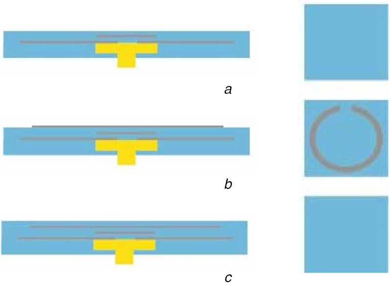
Fig. 1.
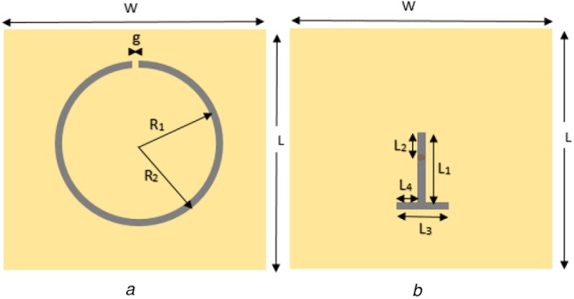
Diagrams showing two sections of the sensor
a Microstrip ring resonator with a single split
b T-shape microstrip line for magnetic feeding
The signal connection was chosen to be perpendicular to the ring's plane and at the centre of the ring's projection on the ground plane. This provided a simple manipulability and robustness of the probe. Therefore, a SMA connector was employed and the signal's transition to a microstrip line was done from the bottom (ground) in the centre of ring's projection, marked by a red spot, and to the extreme wing of the ring opposing the split (microstrip gap) through a T-shape microstrip line section as shown in Fig. 1b. Since there was no direct contact between the T-shape microstrip line and the SRR, this ensured a magnetic excitation opposite to the split of the ring. This is because the split represents a capacitance and the opposite side an inductance.
The sensor consists in three layers of PDMS material: (1) the T-shape microstrip line, (2) the SRR line and (3) a superstrate. The thicknesses of layer numbers 1, 2 and 3 are h2, h3 and h4, respectively. The h1 accounts for a layer of PDMS below the ground plane, as part of an encapsulation of the whole sensor with the superstrate layer closing it. The superstrate physically connects to the head or to the head phantom, which will be explained in the next subsection.
4. Phantom
The main goal of the head phantom is to mimic the dielectric properties of real human head tissues, to reproduce a similar response, which can be used to validate the sensor response. For simplicity, the head has been modelled to have three main homogenous materials whose dielectric properties at the microwave range are comparative to that of the skin, bone and brain. The associated electromagnetic fields have to be confined in the defect region in the bone layer and the signal penetration depth is smaller compared to the total size of the head. Only a significant part of the head phantom was designed. This also saved computation time. The head phantom was modelled as a rectangle with the three essential layers of skin, skull and brain with thicknesses of h5, h6 and h7, respectively, and sizes of W1 × W2. The dielectric property of these head tissues at 2.4 GHz frequency was provided from [30]. In the skull, we assumed that there was a defect. In the head phantom model, the top layer was the skin with a depth of 1 mm and below the skin was the skull with a depth of 6.5 mm, length and width of 51 mm2. A defect of 20 × 20 × 6.5 mm3 was made in the skull, which was filled with bone morphogenetic protein (BMP) bone fillers of the same size. Below the skull layer was the brain. The brain dimensions were length and width 51 mm2, and height 10 mm.
To make phantoms for a unique frequency, the water content and dielectric property must be considered, given that human tissues are composed mostly of water. To maintain this property, agar-based phantoms were chosen for skin, brain and BMP phantom fillers.
For the bone phantom, a harder and durable material was chosen to avoid damage during physical stress. Therefore, gypsum was used to create the skull phantom (bone material). A defect was facilitated in the skull by creating a cubic cavity, which was filled with different samples of BMP bone fillers with varying dielectric constants, from 68 to 18 as shown in Fig. 2, to analyse and validate the transition stages of BMP bone healing. In Fig. 3, the fabricated phantom is shown.
Fig. 2.
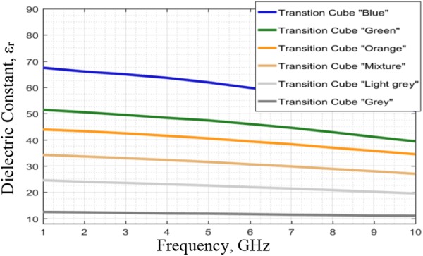
Dielectric constants at different frequencies for BMP bone fillers
Fig. 3.
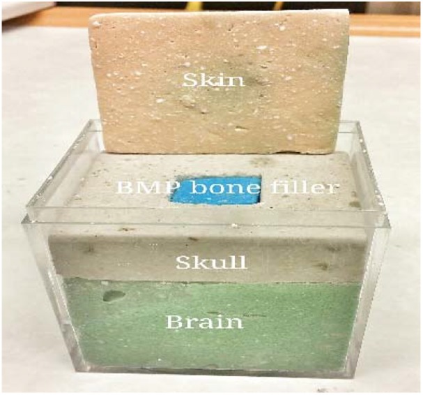
Fabricated phantom
5. Simulation and optimisation
In this work, Computational Software Technology (CST) Microwave Studio™ version 2016 was chosen as the simulation tool and as computer assisting design (CAD) tool. The simulation solver was the frequency domain one and the mesh unit was small enough to include at least five units per object's dimension and maximum simulation wavelength. Open and Open-add-space were the considered simulation boundaries. For simplicity, it was considered a relative permittivity of 3 and a loss tangent of as 0.01 for the PDMS layers for simulations [23]. For the human model, a three-layer model including skin, skull and brain, the biological database from the CAD were employed, while for the defect, frequency-constant materials from a value similar to bone to values close to water were employed. Most of the parameters were optimised so that the resonance frequency could be between 2 and 4 GHz from the extreme cases of air and a high permittivity material on the top of the superstrate. The only predefined parameters were the following, with their respective values in mm: h5 = 1, h6 = 6.5, h7 = 10. W1 = 20 and W2 = 51.
6. Fabrication
The liquid alloy was sprayed with a tape stencil mask to pattern the antenna on a semi-cured PDMS layer. The dielectric PDMS layers were laminated with a film applicator after curing a base-PDMS packaging layer with an embedded SMA connector. Fig. 4 shows the fabrication process in detail.
Fig. 4.
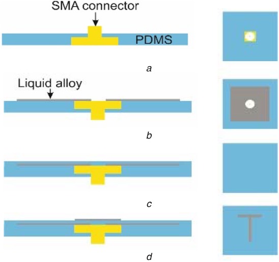
Process schematics (side view to the left and top view to the right) of the fabricated soft electromagnetic antenna, patterned with liquid-alloy-spraying and tape-transfer-masking
a Embedding of SMA connector in PDMS
b Ground layer with liquid alloy
c Layer of PDMS
d Microstrip T-section
First, an SMA connector was moulded in a PDMS layer in a petri-dish as shown in Fig. 4a. Then, on the PDMS layer, the ground layer of the liquid alloy was sprayed with a tape transfer mask to make a square pattern (Fig. 4b). The fabrication process with atomisation patterning of liquid alloys is explained by Joeng et al. [28]. The first dielectric PDMS layer was laminated on the liquid alloy-square pattern with the film applicator and spacers (a supporting structure for the sample and a supporting structure for the film applicator) to have the designed thickness (Fig. 4c). Then, a hole was punched with a flat tip needle through the whole layers to give electrical connection to the SMA pin with the following patterning of the T-section of the liquid alloy. The T-section was patterned with the same process as with the ground plate (Fig. 4d). Then, the second dielectric PDMS layer was laminated with the same process to the first substrate using a different spacer thickness during film application (Fig. 5a).
Fig. 5.
Continued schematics of the process (side view to the left and top view to the right) of the fabricated soft electromagnetic antenna, patterned with liquid-alloy-spraying and tape-transfer-masking
a Layer of PDMS
b Microstrip ring with gap
c Layer of PDMS
Finally, the ring-section was patterned with the same process (Fig. 5b) and the pattern was encapsulated with a final PDMS layer by a film applicator (Fig. 5c). Every PDMS layers were semi-cured at 75°C for a certain time depending on the thickness of the PDMS layer. This is to create a good bonding with the next layer and to make good wetting to the liquid alloy pattern. After all layer fabrication, the whole structure was fully cured at 75°C for 12 h. The thickness of each liquid alloy layer was chosen to be 100 μm.
7. Result and discussion
7.1. Optimisation
As a result of the sensor optimisation using CST Microwave Studio™, the following parameters were obtained (values in mm): L1 = 10, L2 = 1.6, L3 = 4, L4 = 1.6, g = 0.8, R1 = 8.7, R2 = 9.5, h2 = 1, h3 = 0.5 and h4 = 0.2. The sensor was then fabricated trying to meet these values.
7.2. Simulation results
The simulation of the sensor and the phantom model (skin, skull + defect and brain) done with CST Microwave Studio™ showed a poor radiation pattern as expected (typical of a near-field device) and a good portion of the electric field distribution in the defect (target) area (Fig. 6). The skull has permittivity values lower than the skin and the brain. In addition, since the ring resonates at half-wavelengths, between two opposite sides of the ring the polarity is inverse. This suggests that a possible path is through the bone and fillers area.
Fig. 6.
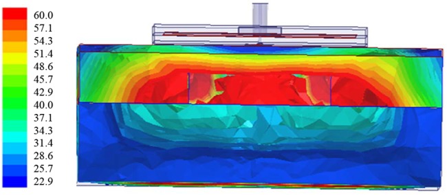
Distribution of electric field after simulation of sensor on phantom with CST Microwave Studio™
The standalone sensor had a resonance frequency of 3.328 GHz with a reflection coefficient of −4.2 dB (Fig. 7). The antenna was simulated again together with three-layer head models incorporating a different filler in the defect areas. The initial relative permittivity of the skull bone fillers was 68 [13]. These skull bone fillers in course of time transform into healthy normal bone, which then will have a relative permittivity around 18.
Fig. 7.
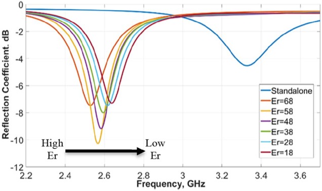
Simulated resonance frequency of antenna with head phantom, with variation in dielectric constant from 18 to 68
In simulations the relative permittivity of the skull bone fillers was varied from 68 to 18. 18 is the normal dielectric constant of the bone. A constant smooth variation in resonance frequency was obtained for the dielectric constant variation from 68 to 18 with 87 MHz frequency separation between the two extremes 18 and 68, as shown in Fig. 7. This demonstrates the device is sensitive to the variations in the defect (target area), specially permittivity variations, which are translated as frequency and amplitude variations of the resonance.
7.3. Measurement results
The measurements were taken by an Agilent E8364B, vector network analyser connected to the SMA connector in the antenna through a coaxial probe (Fig. 8a). The fabricated antenna at standalone had a resonance frequency of −7.3 dB at 3.08 GHz. The difference in the simulated and measured standalone resonance frequency was because of fabrication error. The fabrication was done manually and there is limitation in controlling the thickness of the PDMS and Galinstan layers. The achieved dimensions were (values in mm): W = 30, L = 30 and h1 = 1.1. The fabricated sensor without the SMA connector is shown in Fig. 9. Its overall thickness was about 2.8 mm. The measurements were taken by placing the antenna on the phantom and exerting a constant pressure (Fig. 8a). The bone fillers with different dielectric constants 68, 50, 42 and 18 were placed in the skull cavity and a corresponding shift in resonance frequency was obtained from left to right for each one of these different dielectric constants (Fig. 10). By monitoring this shift in resonance frequency, it is possible to determine the transition of BMP bone fillers to normal skull. Measurements were also taken on a healthy human head for comparison (Fig. 8b). We can see that the measurements on the healthy human head and on the skull phantom with no defect were quite similar. This validated the skull phantom as a control reference.
Fig. 8.
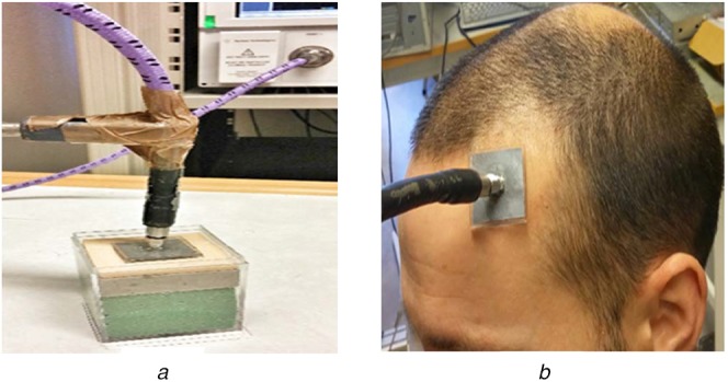
Implementation of soft antenna on human head
a Human head phantom
b Real human head
Fig. 9.
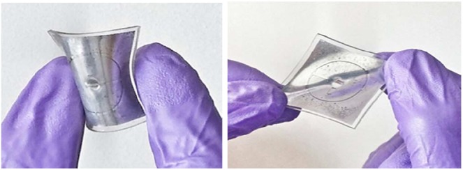
Soft antenna sample showing flexibility and stretchability
Fig. 10.
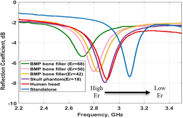
Measured reflection coefficient at different resonance frequencies under various dielectric constant conditions
An aspect to highlight is that these sensors can be fabricated at very low costs. The one fabricated for this work lasted only a few times before it became useless. The connection with the SMA was one of the main issues compromising its durability. Therefore, they should be used as disposables. The aspect to solve is how to do a strong feeding connection, which is also cheap.
7.4. Dynamics' considerations
As stated previously, the present work provides only with static analyses, which approximately considers the different healing stages of a skull bone defect, assuming that both the head phantom and the sensor models are statics.
We neglected the dynamics regarding the head's physiology as changes in the permittivity and geometry of involved tissues should be insignificant at the considered range of frequencies because the changes in their electrical dimensions are much shorter than the minimum considered wavelength.
Dynamics regarding the sensor, mainly mechanical deformations such as stretching, bending and crumpling could produce a significant effect in the electric performance of the sensor [31–33]. These deformations could take place in the head of a less-than-12-month-old child. In fact, skin was found to be very elastic, achieving a mean ultimate skin deformation before bursting of about 75% in newborn children according to Vogel [34] in 1987. Recently, Joodaki and Panzer in a review work [35] confirmed this finding and showed that in general skin elasticity properties are higher, the younger one is, and discussed the anisotropic properties of skin's elasticity referring mainly to Langer's lines. Assuming that maximum deformation stretching of our structure should probably occur along these lines, we expect that, due to the circular geometry of our resonant structure, any deformation will shape the structure to an ellipse. A foreseen effect should be a decrease in the resonance frequency due to a physical enlargement of the ring perimeter, similarly as shown by Rashid et al. [31] in 5.8 GHz microstrip monopoles under certain percentages of stretching. However, in our case an enlargement in the gap width of the microstrip gap capacitor (gap ‘g’ in Fig. 1a) could produce an opposite and compensating effect, increasing the resonance frequency of the resonator. Studies on the effect of bending deformations on the resonance's characteristics were done by Ullah et al. [33] and Elias et al. [32]. The former covered curvature radii from few mm to 35 mm, while the later radii above 50 mm. Findings in [32] show that crumpling is more significant than bending when curvature radii are above 50 mm, and, in addition, support our approach, as both deformations could increase the penetration of the electromagnetic energy into the targeted area, with the cost of implementing a proper measurement protocol. Findings in [33] show that the resonance frequency decreases as the curvature radius decreases as well below 35 mm, whose case presents the smallest difference in the resonance frequency with respect to the flat case. Recalling the third percentile curve in this WHO's chart [36], the minimum estimate for the head circumference in a recently born children could be about 320 mm, therefore, we could estimate that the maximum possible curvature that could exist in newborn children could be about 39 mm, therefore, the detuning produced by bending should not be so significant with respect to crumpling.
8. Conclusion
We presented a head-compliant microstrip split-ring resonator for sensing osteogenesis of calvarial bone after reconstructive procedures from the perspective of craniosynostosis-based craniotomy, which affects mostly newborn children. The head conformability was achieved thanks to the use of the PDMS silicone and a liquid alloy (Galinstan) to fabricate the soft and stretchable printed circuit board. This resonator was studied using CST Microwave Studio®-based and laboratory simulations in a hypothetical scenario conformed by a multi-tissue-layer head phantom emulating different healing stages of a bone defect. Since the conducted simulations were static, a discussion based on an inductive reasoning regarding dynamics’ considerations consisting on physiological and mechanical aspects was also considered in this work.
The computational simulations showed poor radiation pattern as expected (typical of a near-field device) and a good portion of the electric field distribution in the defect (target) area. A fabricated prototype was simulated and analysed, showing a sensitivity similar to the simulated cases. This demonstrated that the device was sensitive to the variations in the defect (target area), specially permittivity variations, which were translated as frequency and amplitude variations of the resonance. An accurate study of the sensitivity and selectivity of the device needs to be addressed.
Regarding the physiological and mechanical considerations, we neglected the former, arguing that most changes would be insignificant due to the involved electrical dimensions and giving some assumptions, and discussed the latter. Newborn children have high skin elasticity, meaning that the device should be easy to stretch and crumple. Due to the circular nature and the presence of the gap capacitor, we believe that a compensation mechanism could take place when stretching, which needs to be studied further. Crumpling should also be taken in consideration in future studies because we believe it could affect significantly the device performance. Under the maximum head curvature in the target children group, no significant changes should occur in the performance characteristics of the device. Moreover, due to bending, more energy could be focused to the defect improving the device sensitivity. This also needs to be further studied in future works.
Our concept could help in devising a novel follow-up monitoring system of the ossification after craniosynostosis-based craniotomy. Such a system would assist the clinician in predicting re-synostosis (a new premature fusion of the sutures) and in giving other useful feedback. This would reduce the use of ionising radiation, which is a concern for new-born paediatric patients. This technological concept could also be applicable to other craniofacial, neurosurgical and orthopaedic conditions where monitoring of bone healing is important.
9. Acknowledgments
The authors thank Paul John Babu for his contribution to the data collection during his Master thesis. This work was partially supported by the Eurostars project under grant E-9655-COMFORT, Indo-Swedish VINNOVA/DST project under grant BDAS (2015-04159), Swedish Research Council (Vetenskaprådet, VR) project Osteodiagnosis (2017-04644), Horizon 2020 Framework Programme (European Union) project 824984-SINTEC and the UGC (Government of India) that provided financial assistance under UGC-FRP program.
10 References
- 1.‘Worldometers’, worldometers.info, accessed 19 August 2018
- 2.Greenwood J., Flodman P., Osann K., et al. : ‘Familial incidence and associated symptoms in a population of individuals with nonsyndromic craniosynostosis’, Genet. Med., 2014, 16, (4), pp. 302–310, (doi: 10.1038/gim.2013.134) [DOI] [PMC free article] [PubMed] [Google Scholar]
- 3.Johnson D., Wilkie A.O.M.: ‘Craniosynostosis’, Eur. J. Hum. Genet., 2011, 19, (4), p. 369–76, (doi: 10.1038/ejhg.2010.235) [DOI] [PMC free article] [PubMed] [Google Scholar]
- 4.Tahiri Y., Bartlett S.P., Gilardino M.S.: ‘Evidence-based medicine: nonsyndromic craniosynostosis’, Plast. Reconstr. Surg., 2017, 140, (1), pp. 177–191, (doi: 10.1097/PRS.0000000000003473) [DOI] [PubMed] [Google Scholar]
- 5.Grau N., Daw J.L., Patel R., et al. : ‘Nanostructural and nanomechanical properties of synostosed postnatal human cranial sutures’, J. Craniofac. Surg., 2006, 17, (1), pp. 91–98 (doi: 10.1097/01.scs.0000179754.52154.42) [DOI] [PubMed] [Google Scholar]
- 6.Arnaud E., Capon-Degardin N., Michienzi J., et al. : ‘Scaphocephaly part II: secondary coronal synostosis after scaphocephalic surgical correction’, J. Craniofac. Surg., 2009, 20, (Suppl 2), pp. 1843–1850, (doi: 10.1097/SCS.0b013e3181b6c4c3) [DOI] [PubMed] [Google Scholar]
- 7.Isaevska E., Manasievska M., Alessi D., et al. : ‘Cancer incidence rates and trends among children and adolescents in piedmont, 1967–2011’, PLoS ONE, 2017, 12, (7), p e0181805, (doi: 10.1371/journal.pone.0181805) [DOI] [PMC free article] [PubMed] [Google Scholar]
- 8.Applegate K.E., Cost N.G.: ‘Image gently: A campaign to reduce children's and adolescents’ risk for cancer during adulthood’, J. Adolescent Health, 2013, 52, (5 Suppl), pp. S93–S97, (doi: 10.1016/j.jadohealth.2013.03.006) [DOI] [PubMed] [Google Scholar]
- 9.Siegel J.A., Sacks B., Pennington B., et al. : ‘Dose optimization to minimize radiation risk for children undergoing CT and nuclear medicine imaging Is misguided and detrimental’, J. Nucl. Med., 2017, 58, pp. 865–868, (doi: 10.2967/jnumed.117.195263) [DOI] [PubMed] [Google Scholar]
- 10.Ideguchi R., Yoshida K., Ohtsuru A., et al. : ‘The present state of radiation exposure from pediatric CT examinations in Japan—what do we have to do?’, J. Radiat. Res., 2018, 59, pp. ii130–ii136, (doi: 10.1093/jrr/rrx095) [DOI] [PMC free article] [PubMed] [Google Scholar]
- 11.Binning M., Ragel B., Brockmeyer D.L., et al. : ‘Evaluation of the necessity of postoperative imaging after craniosynostosis surgery’, J. Neurosurg., 2007, 107, (Suppl 1), pp. 43–45 [DOI] [PubMed] [Google Scholar]
- 12.Augustine R., Alves R., Sarrebourse T., et al. : ‘Polymeric ferrite sheets for SAR reduction of wearable antennas’, Electron. Lett., 2010, 46, pp. 197–198, (doi: 10.1049/el.2010.3246) [Google Scholar]
- 13.Raman S., Augustine R., Rydberg A., et al. : ‘Noninvasive osseointegration analysis of skull implants with proximity coupled split ring resonator antenna’, IEEE Trans. Antennas Propag., 2014, 62, pp. 5431–5436, (doi: 10.1109/TAP.2014.2350522) [Google Scholar]
- 14.Perez M.D., Thomas G.G., Redzwan S.M.S., et al. : ‘Preliminary study on microwave sensor for bone healing follow-up after cranial surgery in newborns’. Proc., 2018 EUCAP, 12th European Conf. on Antennas and Propagation, London, April 2018, DOI: 10.1049/cp.2018.1250 [Google Scholar]
- 15.Perez M.D., Mattsson V., Redzwan S.M.S., et al. : ‘New approach for clinical data analysis of microwave sensor based bone healing monitoring system in craniosynostosis treated pediatric patients’. Proceeding, 2018 IEEE CAMA - Conf. on Antenna Measurement and Applications, Västerås, September 2018, DOI: 10.1109/CAMA.2018.8530485 [Google Scholar]
- 16.Mathur P., Kurup D.G., Augustine R.: ‘Design of open-ended circular waveguide for non-invasive monitoring of cranial healing in pediatric craniosynostosis’. Proc., 2017 First IEEE MTT-S Int. Microwave Bio Conf. (IMBIOC), Gothenburg, Sweden, May 15–17, 2017, DOI: 10.1109/IMBIOC.2017.7965784 [Google Scholar]
- 17.Augustine R., Kurup D.G., Redzwan S.M.S., et al. : ‘Microwave reflectivity analysis of bone mineral density using ultra wideband antenna’, Microw. Opt. Technol. Lett., 2017, 59, pp. 21–26, (doi: 10.1002/mop.30210) [Google Scholar]
- 18.Lee D., Nowinski D., Augustine R.: ‘Preliminary research on skull healing utilizing short pulsed radar technique on layered cranial surgery phantom models’, Progr. Electromagn. Res C, 2018, 84, pp. 1–9, (doi: 10.2528/PIERC18022604) [Google Scholar]
- 19.Lee D., Nowinski D., Augustine R.: ‘A UWB sensor based on resistively-loaded dipole antenna for skull healing on cranial surgery phantom models’, Microw. Opt. Technol. Lett., 2018, 60, pp. 897–905, (doi: 10.1002/mop.31077) [Google Scholar]
- 20.Wu Z., Hjort K., Jeong S.H.: ‘Microfluidic stretchable radio-frequency devices’, Proc. IEEE, 2015, 103, pp. 1211–1225, (doi: 10.1109/JPROC.2015.2395716) [Google Scholar]
- 21.Brand J., Kok M., Sridhar A., et al. : ‘Flexible and stretchable electronics for wearable healthcare’. 2014 44th European Solid State Device Research Conf. (ESSDERC), Venice Lido, Italy, September 22–26, 2014, DOI: 10.1109/ESSDERC.2014.6948796 [Google Scholar]
- 22.Cheng S., Rydberg A., Hjort K., et al. : ‘Liquid metal stretchable unbalanced loop antenna’, Appl. Phys. Lett., 2009, 94, p. 144103, (doi: 10.1063/1.3114381) [Google Scholar]
- 23.Song L., Myers A.C., Adams J. J., et al. : ‘Stretchable and reversibly deformable radio frequency antennas based on silver nanowires’, ACS Appl. Mater. Interfaces, 2014, 6, pp. 4248–4253, (doi: 10.1021/am405972e) [DOI] [PubMed] [Google Scholar]
- 24.Rai T., Dantes P., Bahreyni B., et al. : ‘A stretchable RF antenna with silver nanowires’, IEEE Electron Device Lett., 2013, 34, pp. 544–546, (doi: 10.1109/LED.2013.2245626) [Google Scholar]
- 25.Zhou Y., Bayram Y., Du F., et al. : ‘Polymer-Carbon nanotube sheets for conformal load bearing antennas’, IEEE Trans. Antennas Propag., 2010, 58, pp. 2169–2175, (doi: 10.1109/TAP.2010.2048852) [Google Scholar]
- 26.Liu T., Sen P., Kim C.: ‘Characterization of nontoxic liquid-metal alloy Galinstan for applications in microdevices’, J. Microelectromech. Syst., 2012, 21, pp. 443–450, (doi: 10.1109/JMEMS.2011.2174421) [Google Scholar]
- 27.Mata A., Fleischman A.J., Roy S.: ‘Characterization of polydimethylsiloxane (PDMS) properties for biomedical micro/nanosystems’, Biomed. Microdevices, 2005, 7, (4), pp. 281–293, (doi: 10.1007/s10544-005-6070-2) [DOI] [PubMed] [Google Scholar]
- 28.Jeong S.H., Hjort K., Wu K.: ‘Tape transfer atomization patterning of liquid alloys for microfluidic stretchable wireless power transfer’, Sci. Rep., 2015, 5, p. 8419, (doi: 10.1038/srep08419) [DOI] [PMC free article] [PubMed] [Google Scholar]
- 29.Shah S.R.M., Velander J., Mathur P., et al. : ‘Split-ring resonator sensor penetration depth assessment using In vivo microwave reflectivity and ultrasound measurements for lower extremity trauma rehabilitation’, Sensors, 2018, 18, (2), p. 636, (doi: 10.3390/s18020636) [DOI] [PMC free article] [PubMed] [Google Scholar]
- 30.‘Calculation of the dielectric properties of body tissues in the frequency range 10 Hz - 100 GHz’, IFAC-CNR, accessed 24 August 2018, available at http://niremf.ifac.cnr.it/tissprop/htmlclie/htmlclie.php
- 31.Rashid T., Noghanian S., Fazel-Rezai R., et al. ‘Stretching effect on textile antenna for spacesuit'. 2016 IEEE Int. Symp. on Antennas and Propagation (APSURSI), Fajardo, 2016, pp. 995–996. doi: 10.1109/APS.2016.7696206 [Google Scholar]
- 32.Elias N.A., Samsuri N.A., Kamal M., et al. : ‘Bending and crumpling deformation study of the resonant characteristic and SAR for a 2.4 GHZ textile antenna’, J. Teknol., 2015, 77, (10), pp. 17–23. Available at 10.11113/jt.v77.6278 [DOI] [Google Scholar]
- 33.Ullah M.A., Islam M.T., Alam T., et al. : ‘Paper-based flexible antenna for wearable telemedicine applications at 2.4 GHz ISM Band', Sensors, 2018, 18, (12), p. 4214. (doi: 10.3390/s18124214) [DOI] [PMC free article] [PubMed] [Google Scholar]
- 34.Vogel H.G.: ‘Age dependence of mechanical and biochemical properties of human skin. Part I. Stress-strain experiments, skin thickness and biochemical analysis', Bioeng. Skin, 1987, 3, pp. 67–91 [Google Scholar]
- 35.Joodaki H., Panzer M.B.: ‘Skin mechanical properties and modeling: A review', Proc. Inst. Mech. Eng., Part H: J. Eng. Med., 2018, 232, (4), pp. 323–343. Available at 10.1177/0954411918759801 [DOI] [PubMed] [Google Scholar]
- 36.World Health Organization: ‘Head circumference for age: boys, birth to 5 years (percentiles)', accessed on 17 August 2019, available at URL: https://bit.ly/2EU0Wli