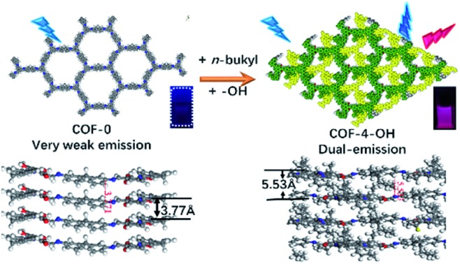
 The introduction of hydroxyl groups and n-butyl groups into COF-4-OH for the construction of COFs with strong dual emission was demonstrated.
Abstract
Here we reveal the effects of hydrogen bonds and alkyl groups on the structure and emission of covalent organic frameworks (COFs). Hydrogen bonds improve molecular rigidity leading to high crystallinity and restrict intramolecular rotation to enhance the emission of COFs. An excited-state intramolecular proton transfer (ESIPT) effect for dual emission is achieved via the intramolecular hydrogen bonds between hydroxyl groups and imine bonds. Alkyl groups increase interlayer spacing as a natural “scaffold” and achieve a staggered AB stacking mode to decrease aggregation-caused quenching. Based on the above guidance, COF-4-OH with strong emission is prepared with 2,4,6-triformylphloroglucinol (TFP) and 9,9-dibutyl-2,7-diaminofluorene (DDAF). Strong dual emission is observed and used to differentiate organic solvents with different polarities, to determine the water content in organic solvents, and to detect different pH levels. Our work serves as a guide for the rational design of functional monomers for the preparation of emissive COFs.
Introduction
Covalent organic frameworks (COFs) are a class of porous polymers prepared from organic building blocks with designable structures.1 Abundant monomers enable the realization of a wide range of applications of COFs.2–6 The properties of COFs can be designed and regulated at the atomic level by selecting appropriate monomers.7–9 Thus, COFs are expected to be supplementary molecular luminophores owing to their natural π-conjugated structure. Chromophore and aggregation-induced emission (AIE) cores have been used to prepare emissive COFs.10–16 3-Dimensional COFs are a good platform for the preparation of emissive COFs, but the available molecular building blocks are limited.10,17 The main obstacles of fluorescent 2-dimensional COFs are non-radiative relaxation induced from intramolecular rotation and π–π stacking self-quenching.18
Hydrogen bonds can enhance the emission of COFs by restriction of the intramolecular rotation (RIR). 2,4-Dihydroxybenzene-1,3,5-tricarbaldehyde and anthracene-2,6-diamine were used to prepare emissive COFs by the formation of intramolecular hydrogen bonds.19 The emission was improved for the COFs prepared with 1,6-diaminopyrene and 1,3,5-triformilfloroglucionol with intramolecular hydrogen bonds for RIR.8 Interlayer and intralayer hydrogen bonds were confirmed to restrict intramolecular rotation with an eclipsed stacking mode to enhance the emission of COFs.20
Aggregation-caused quenching (ACQ) is another factor that disturbs the emission of COFs because of the π–π stacking self-quenching. Mechanical exfoliation of nanosheets improves the emission of COFs by reducing π–π stacking, but it is energy- and time-consuming.12,21 Fluorescent COF nanosheets have been obtained through self-exfoliation.22 Steric hindrance of the side chains in monomers reduces the π–π stacking and regulates the stacking mode of COFs to overcome ACQ.23–25 Pang et al. introduced ethyl or butyl groups into monomers to prepare COFs from 2,5-diethoxyterephthalaldehyde and 4,4′,4′′,4′′′-(ethene-1,1,2,2-tetrayl)tetraaniline.26 A different COF topology was realized. The various topologies and stacking modes may regulate the π–π stacking to improve the emission, but the authors did not study the emission properties of their COFs.
Guidance on how to decrease intramolecular rotation and ACQ for emissive COFs is still limited. Intramolecular rotation of COFs increases thermal decay, which leads to a low quantum yield.27 Large interlayer spacing decreases ACQ but increases molecular rotation; thus, ACQ and intramolecular rotation are a dilemma. Intramolecular hydrogen bonds increase molecular rigidity and decrease intramolecular rotation.28 The interlayer spacing and stacking mode govern the interlayer interaction.29 Thus, intramolecular rotation, interlayer spacing, and stacking mode are the critical keys for the emission of COFs. In addition to emission intensity, multiple emission and a large Stokes shift are also attractive for real applications.30–32 Multiple emission enables ratiometric fluorescence sensing and visual detection.33,34 A large Stokes shift decreases the interference from the excitation light.
Herein, we reveal the role of hydroxyl and alkyl groups in the preparation of emissive COFs with careful design of monomers. As the optimal structure, COF-4-OH (“4” and “OH” represent n-butyl and hydroxyl groups, respectively) was prepared with 2,4,6-triformylphloroglucinol (TFP) and 9,9-dibutyl-2,7-diaminofluorene (DDAF) through the Schiff base reaction. Intramolecular hydrogen bonds form between hydroxyl groups and imine nitrogen to induce RIR. Moreover, the hydrogen bond achieves excited-state intramolecular proton transfer (ESIPT) for dual emission at 400 and 590 nm under single excitation at 280 nm with a large Stokes shift. The n-butyl groups act as a natural “scaffold” to increase the interlayer spacing and achieve a staggered AB mode to decrease the interlayer stacking in traditional COFs. The dilemmatic ACQ and intramolecular rotation are simultaneously eliminated. The strong dual emission, in combination with multi-active sites, such as the hydroxyl, alkyl, and imine groups in COF-4-OH, is used to differentiate solvents with different polarities, to determine the water content in organic solvents, and to detect pH. We trust that the results could serve as guidance for preparing fluorescent COFs with strong dual emission by the rational introduction of functional groups into the monomers.
Results and discussion
COFs design to reveal the effect of hydroxyl and alkyl groups
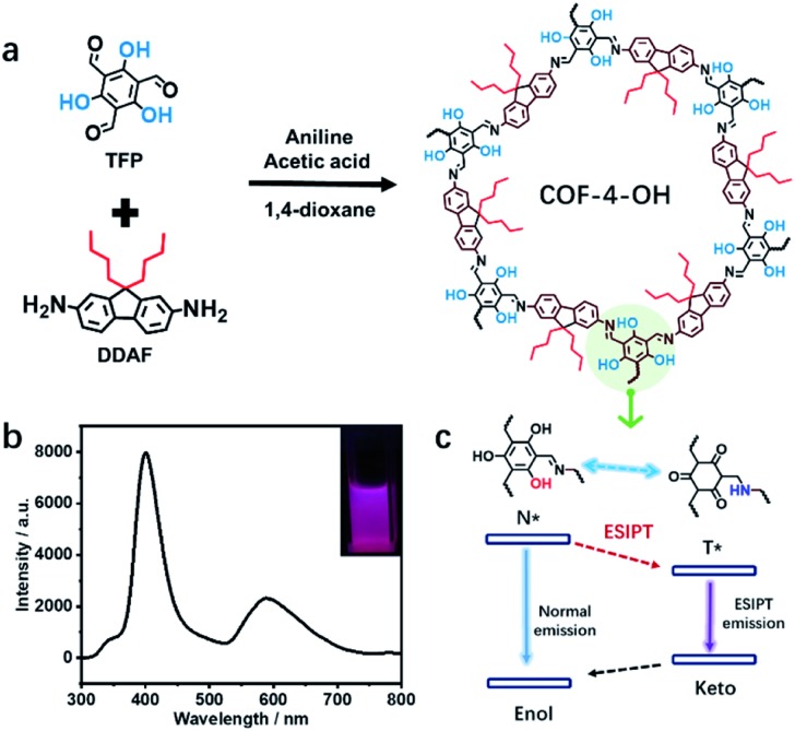
How to obtain highly fluorescent COFs still lacks guidance. The introduction of hydroxyl groups into the precursors is simple and practical for the preparation of emissive COFs.8,19,20 Alkyl groups with different sizes influence the stacking mode and interlayer spacing of COFs to regulate their luminescence. Thus, TFP and 1,3,5-triformylbenzene (TFB) without hydroxyl groups are selected as aldehyde group-containing monomers. 2,7-Diaminofluorene (DAF) with two R groups (R = H, n-butyl, or n-octyl) on the same side is used as the amino-group-containing monomers (Fig. S1a†). The Schiff base reaction between the aldehyde and amino groups enables the formation of different COFs (Fig. S1b†). Therefore, the effect of hydroxyl and alkyl groups on the structure and emission of COFs is revealed (Scheme 1a). The n-butyl groups overcome ACQ, while –OH groups are used to form hydrogen bonds with imine nitrogen to induce RIR and realize ESIPT for dual emission under single excitation (Scheme 1b). Thus, strong dual emission is observed. The mechanism of ESIPT for dual emission is also revealed (Scheme 1c).
Scheme 1. (a) The design of COFs to reveal the effects of hydroxyl and alkyl groups and the ESIPT procedure, showing hydroxyl-functional TFP and alkyl groups-containing DDAF for the preparation of COF-4-OH. (b) Dual emission from COF-4-OH under 280 nm excitation; inset: a picture of COF-4-OH under 280 nm illumination. (c) The ESIPT dual emission mechanism of hydroxyl-containing COF-4-OH.
Effects of hydroxyl and alkyl groups on the structure of COFs
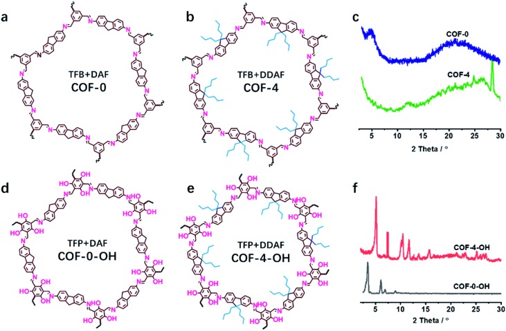
The effect of a hydroxyl group on the structure of COFs was firstly tested. COF-0 was prepared with DAF and TFB as monomers (Fig. 1a),35 whereas COF-4 was prepared with TFB and DDAF as monomers (Fig. 1b). No characteristic peak was observed in their PXRD patterns (Fig. 1c) with a spherical structure (Fig. S2a and b†). As a comparison, TFP was selected to react with DDAF or DAF to prepare COF-4-OH or COF-0-OH, respectively (Fig. 1d and e). Characteristic peaks were observed from their PXRD patterns (Fig. 1f) to illustrate their higher crystallinity than COF-0 and COF-4. Intramolecular hydrogen bonds formed between imine nitrogen and hydroxyl groups, so intramolecular rotation decreased and the single layers of the COFs became rigid. The rigid layers stacked together regularly to produce crystalline COF-0-OH and COF-4-OH with a rod-like structure (Fig. S2c and d†). Intramolecular hydrogen bonds act as a “lock” for RIR to achieve high crystallinity. The higher rigidity of the single layer may not result in a better PXRD pattern, but the good pattern clearly indicates that there is less intramolecular rotation. Thus, the intractable non-radiative decay induced by intramolecular rotation is overcome by the introduction of hydroxyl groups. However, interlayer stacking may occur, so stacking quenching or ACQ can still happen in COFs.
Fig. 1. The structures of (a) COF-0 and (b) COF-4, and (c) their PXRD patterns. The structures of (d) COF-0-OH and (e) COF-4-OH, and (f) their PXRD patterns.
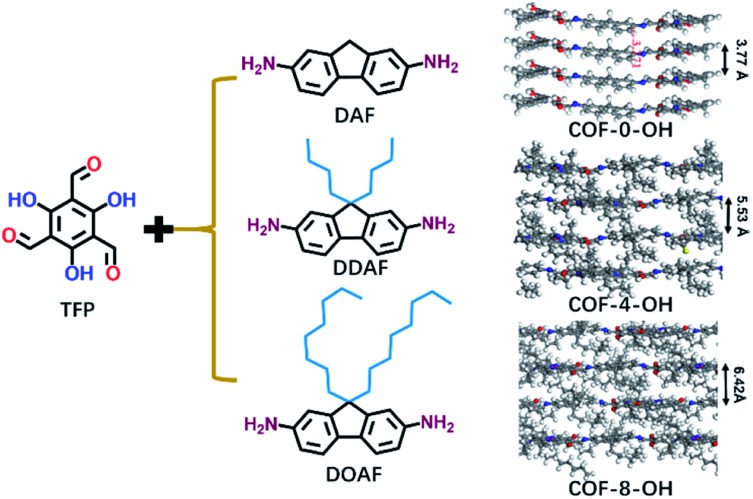
Alkyl groups with different lengths were tested to determine the interlayer spacing that can be utilized to overcome π–π stacking. The following COFs with different alkyl groups were prepared: COF-0-OH, COF-4-OH, and COF-8-OH (where “0”, “4”, and “8” represent no alkyl groups, n-butyl groups, and n-octyl groups, respectively). A gradual increase in the interlayer spacing was observed with 3.77, 5.53, and 6.42 Å for COF-0-OH, COF-4-OH, and COF-8-OH, respectively (Fig. 2; more details are listed in Fig. S3–S5†). Generally, when the interlayer spacing is larger than 3.8 Å, the energy transfer from stacking interaction can be ignored.36,37 Therefore, ACQ from π–π stacking is eliminated in COF-4-OH and COF-8-OH because the alkyl groups act as “scaffold” to prop up the layers. However, the interlayer spacing of the COFs increased nonlinearly. COF-4-OH with n-butyl groups showed a 1.76 Å improvement over COF-0-OH, whereas a difference of 0.89 Å was observed between COF-8-OH and COF-4-OH. The enfoldment and twisting of long n-octyl groups are responsible for the low interlayer spacing improvement.
Fig. 2. The formation of COF-0-OH, COF-4-OH, and COF-8-OH to reveal the effects of alkyl groups on the interlayer spacings of different COFs.
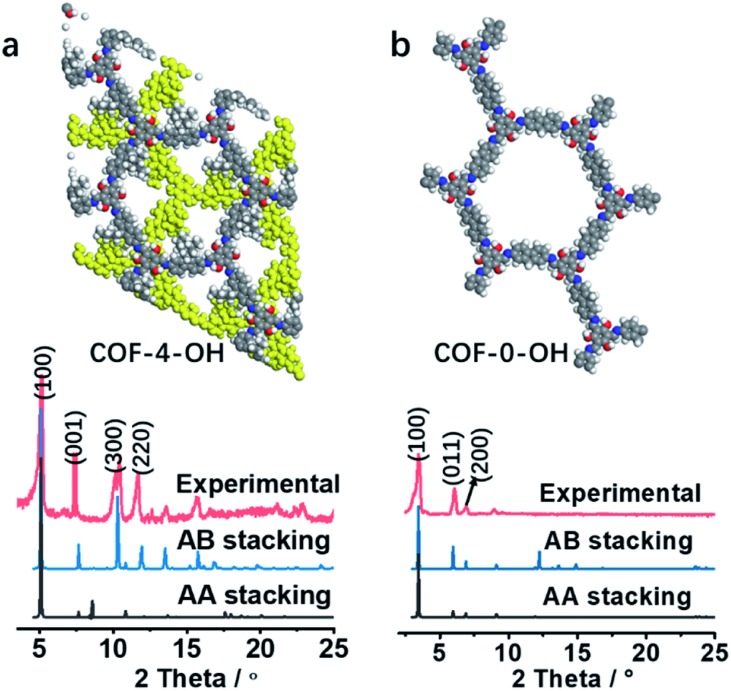
The stacking mode is another factor that influences the structure and fluorescence of COFs. The PXRD patterns were recorded to reveal the influence of the alkyl and –OH groups on the stacking mode and crystallinity of COFs. As shown in Fig. 3a, the AB model was consistent with the experimental PXRD pattern of COF-4-OH with an Rwp value of 9.45% and an Rp value of 6.53% after Pawley refinement. The strong PXRD peaks at 5.03°, 7.62°, 10.50°, and 11.68° in COF-4-OH were assigned to the (100), (001), (300), and (220) facets, respectively (Fig. 3a). COF-0-OH exhibited a classical AA stacking with PXRD peaks at 3.45°, 5.94° and 6.89° for the (100), (011), and (200) facets, respectively (Fig. 3b). Meanwhile, both COF-4-OH and COF-0-OH, with the help of –OH for the intramolecular hydrogen bonds, showed good PXRD patterns and thus high crystallinity. However, no obvious characteristic peaks were observed from the pattern of COF-8-OH because of the enfoldment and twisting of the long and soft n-octyl groups (Fig. S6†). Thus, overlong alkyl groups do not ensure the high crystallinity of COFs. COF-4 with soft n-butyl groups also exhibited a poor PXRD pattern because of intramolecular rotation without the help of –OH (Fig. S7†). As a conclusion, –OH groups induce RIR to improve the rigidness of the single layer and thus realize COFs with high crystallinity. Larger alkyl groups result in a poorer PXRD pattern and lower crystallinity of the COFs because of the loose layer-by-layer stacking. Appropriate alkyl groups, such as n-butyl groups, allow COF-4-OH AB stacking.
Fig. 3. (a) The experimental PXRD and refined PXRD patterns, and the AB staggered stacking mode of COF-4-OH. (b) The experimental PXRD and refined PXRD patterns, and the AA eclipsed stacking mode of COF-0-OH.
Characterization of COFs
Fourier transform-infrared (FTIR) spectra were recorded to reveal the formation and structure of the COFs. For DDAF, the characteristic peak of C N appeared at 1614 cm–1 and N–H peaks at about 3300 cm–1 disappeared to illustrate the occurrence of the Schiff base reaction (Fig. S8†). The n-butyl groups were observed in the FTIR spectra of COF-4-OH and DDAF. The peak of the imine bond was observed at 1614 cm–1 for both COF-4 and COF-0-OH (Fig. S9 and S10†). The carbon peak of C N was observed at 138 ppm by 13C solid-state nuclear magnetic resonance (NMR) spectroscopy, indicating the successful formation of the imine bond (Fig. S11†). Signals between 13 and 25 ppm were related to the n-butyl groups in COF-4-OH and COF-4.
The keto and enol states were confirmed by FTIR and NMR spectra after COF-4-OH was soaked in methanol and n-hexane, respectively. The wide absorption around 3300–3700 cm–1 in the FTIR spectra was regarded as –OH groups for the enol state of COF-4-OH in methanol; the characteristic peak of C O was clearly observed at 1715 cm–1 from COF-4-OH in hexane solution to reveal the existence of the keto state (Fig. S12†). The keto and enol states were also identified from the NMR spectra of COF-4-OH. The peak of C–OH at 153 ppm is related to the enol state and that of C O at 147 ppm is observed for the keto state (Fig. S13†).
The permanent porosity and Brunauer–Emmett–Teller (BET) surface areas of COF-4-OH and COF-0-OH were characterized via N2 adsorption–desorption analysis at 77 K (Fig. S14†). The surface area of COF-4-OH was 34 m2 g–1 with a total pore volume of 0.11 cm3 g–1, whereas that of COF-0-OH was 339 m2 g–1 with a total pore volume of 0.50 cm3 g–1 at P/P0 = 0.99. The alkyl groups reduced the pore volume and surface area of COF-4-OH, so the porosity of COF-4-OH was lower than that of COF-0-OH. The BET specific surface area of COF-4-OH is quite low, which is similar to many other reported COFs with alkyl groups or guest molecules blocking their pores.24,35 The pore size of COF-4-OH is 5.0 Å obtained from BET analysis and is less than the simulated result of about 7.3 Å obtained with Material Studio (Fig. S15†). As a comparison, the pore size of COF-0-OH obtained from the BET analysis and the simulation is 20.1 Å and 27.7 Å, respectively (Fig. S16†). No remarkable weight loss was observed from COF-4-OH and COF-0-OH up to 380 °C; meanwhile, COF-4 was stable up to 300 °C, as indicated by thermogravimetric analysis (Fig. S17–S19†). We also tested the chemical stability of COF-4-OH by dispersing it in tetrahydrofuran, water, ethanol, HCl (pH 1), and NaOH (pH 14) solutions at 25 °C for 24 h. The characteristic absorption bands of C N were still observed in the FTIR spectra (Fig. S20†) so COF-4-OH was sufficiently stable for practical application.
Optical properties
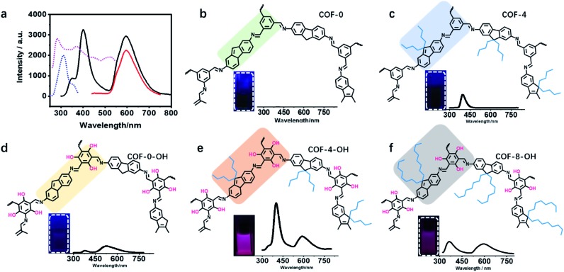
The UV-vis absorption spectra of the monomers and COF-4-OH were investigated. TFP exhibited two absorption peaks at 270 and 370 nm, whereas DDAF showed an absorption peak at 300 nm (Fig. S21†). After the formation of COF-4-OH, the main absorption band was red-shifted to 440 nm by the formation of the π-conjugated system. Intramolecular hydrogen bonds were evidenced by the shoulder peak at approximately 510 nm. DDAF showed stronger fluorescence than DAF; meanwhile, the emission of TFP was red-shifted to 500 nm compared with that of TFB (Fig. S22†). COF-4-OH owns two emission bands at 400 and 590 nm. While the emission at 590 nm was efficiently excited from 280 to 500 nm, that at 400 nm was excited from 270 to 350 nm (Fig. 4a). On the basis of the 3D fluorescence mapping of COF-4-OH (Fig. S23†), under 280 nm excitation, equal dual emission was obtained. Hence, we selected 280 nm as the optimal excitation.
Fig. 4. The fluorescence properties of different COFs. (a) The fluorescence excitation and emission spectra of COF-4-OH; the dashed lines are excitation spectra; blue: 400 nm as emission; purple: 590 nm as emission; solid lines are emission spectra; black: under excitation of 280 nm; red: under excitation of 400 nm. Part structures of different COFs and pictures of COFs in DMF and their fluorescence profiles under 280 nm excitation: (b) COF-0, (c) COF-4, (d) COF-0-OH, (e) COF-4-OH, and (f) COF-8-OH.
The luminescence of different COFs is recorded and discussed in terms of their structure, such as layer rigidity, interlayer spacing, and stacking mode. Nearly no emission was observed from COF-0 because of interlayer stacking and intramolecular rotation (Fig. 4b). Single emission was observed at 400 nm from COF-4 and the fluorescence quantum yield was about 0.1% (Fig. 4c). Although intramolecular rotation still exists, interlayer spacing is increased by the introduction of n-butyl groups, so the fluorescence is slightly enhanced for COF-4. After the introduction of hydroxyl groups, intramolecular hydrogen bonds formed, so dual emission with ESIPT effect is observed from COF-0-OH. However, the emission is weak with a quantum yield of 0.3% because of π–π stacking (Fig. 4d). After hydroxyl groups and n-butyl were synergistically introduced, strong dual emission was observed from COF-4-OH and the quantum yield increased to 10.7% (Fig. 4e). COF-8-OH exhibits dual emission but the intensity is weaker than that of COF-4-OH with blue-shift (Fig. 4f). The low crystallinity of COF-8-OH is responsible for its low fluorescence intensity. The enfoldment and twisting of long and soft n-octyl groups led to irregular stacking in COF-8-OH. Thus, the non-radiative relaxation was enhanced, which decreased the emission of COF-8-OH.
Table S1† illustrates the emission wavelengths and quantum yields of different COFs. Fig. S24† provides the dual emission fluorescence profiles, where COF-4-OH showed the highest quantum yield. Two emissions were observed at 400 and 590 nm under single excitation of 280 nm. The Stokes shifts were 120 nm (83 333 cm–1) and 310 nm (32 258 cm–1), respectively, to avoid interference from the excitation light. Dual emission with a wavelength difference of 190 nm (80 075 cm–1) is useful for ratiometric fluorescence sensing without interfering with each other. Thus, COF-4-OH was selected for further study in terms of its strong dual emission, large Stokes shift, and big gap between the two emissions.
ESIPT mechanism
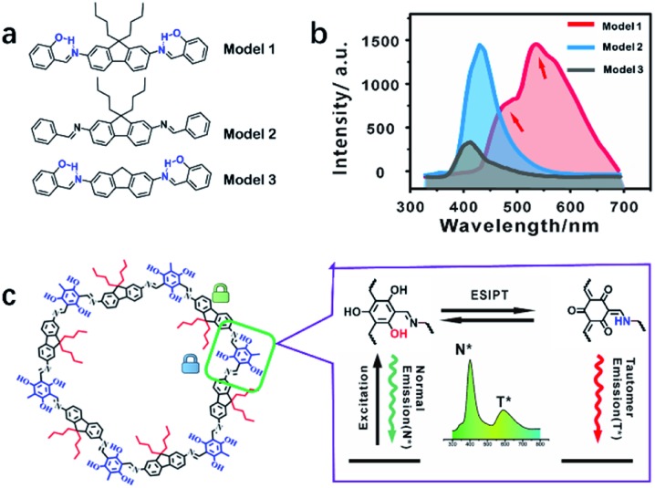
The emission mechanism was explored using three molecular models (Fig. 5a and S25–27†). Model 1 showed dual emission to illustrate that both the alkyl and hydroxyl groups were essential (Fig. 5b and S28†). Model 2 only exhibited single fluorescence because of the absence of an ESIPT structure without a hydroxyl group (Fig. S29†). Model 3 showed weak dual emission: the normal emission and the tail peak as ESIPT emission. Without the supporting effect of n-butyl groups, Model 3 molecules stack together and suffer from self-quenching for the lowest emission among the three models (Fig. 5b and S30†). The emission centers and quantum yields of the models are listed in Table S1.† COF-4-OH showed a larger wavelength gap than Model 1 because the π-conjugated system resulted in the two emissions shifting in opposite directions (Fig. S31†).38
Fig. 5. (a) The structures of the three models: Model 1 vs. COF-4-OH, Model 2 vs. COF-4, and Model 3 vs. COF-0-OH. (b) Fluorescence spectra of the three models. (c) COF-4-OH fragment (left) and hydrogen bonding between the hydroxyl group and the nitrogen of imine realizes the ESIPT procedure for dual emission in COF-4-OH (right).
Fig. 5c illustrates the ESIPT process for the dual emission of COF-4-OH. The blue emission at 400 nm was normal fluorescence from the enol state, whereas that at 590 nm with a larger Stokes shift was the ESIPT emission. The n-butyl groups and intramolecular hydrogen bonds act as dual locks for RIR to enhance the dual emission. The lifetime is 0.8 ns and 1.2 ns for the emissions from COF-4-OH at 400 and 590 nm, respectively (Fig. S32†). The lifetime of the ESIPT emission is a little longer than that of the normal emission.
Time-dependent density functional theory (TD-DFT) calculation was used to determine the barrier gap between the enol and keto states (Fig. S33†). The barrier gap is 3.7 kcal mol–1, indicating that ESIPT happened in the COF-4-OH system.39 The strong dual emission was convenient for further use of COF-4-OH as a probe because of the large Stokes shift and the big gap between the dual emissions.
The fluorescence profiles during the formation of COF-4-OH were recorded to further validate the ESIPT effect. The intensity at about 410 nm decreased, whereas that at 550 nm increased gradually (Fig. S34†). Moreover, the emission at 410 nm blue-shifted, whereas that at 550 nm red-shifted along with the reaction. The two emissions shifted in opposite directions after the formation of the π-conjugated system. It is an important property of ESIPT structures to validate the gradual formation of COF-4-OH. ESIPT emission occurs from intramolecular proton transfer in the excited state of COF-4-OH, so single excitation achieves dual emission and COF-4-OH is expected to be applied as a probe in ratiometric fluorescence sensing.
Multi-target detection with COF-4-OH as a probe
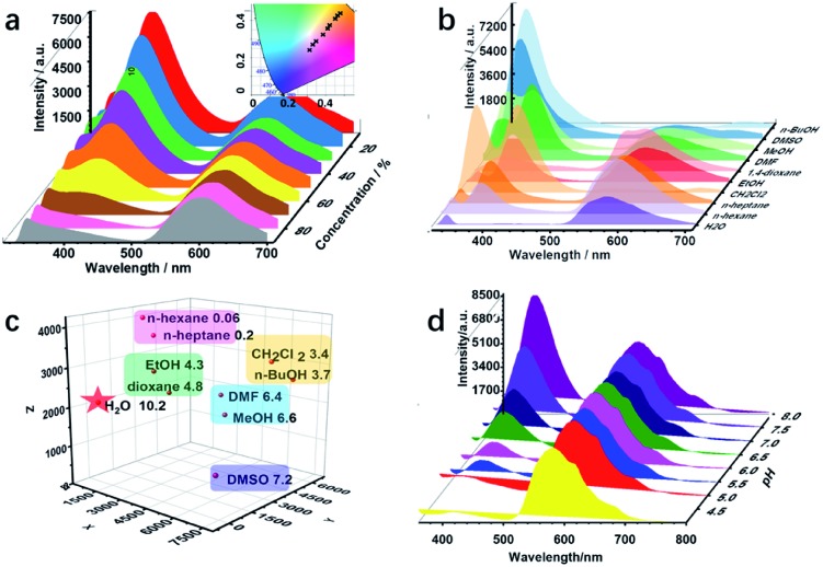
Various active sites, such as imine, hydroxyl, and alkyl groups, exist in COF-4-OH and encourage us to explore multiple recognition. Water is often considered as a contaminant in organic solvents, and even trace amounts of water may cause failure in some chemical laboratories and industries.40 Thus, there is an urgent requirement to develop a simple water detection strategy. COF-4-OH is sensitive to water content in organic solvents with its intramolecular hydrogen bonds. The fluorescence intensity at 400 nm decreased, whereas that at 590 nm remained stable in ethanol with increased water content (Fig. 6a). The ratio of the two emissions decreased linearly for ratiometric sensing of water content (Fig. S35†). A color change from blue to red was clearly observed from the CIE chromaticity coordinates (inset in Fig. 6a). The limit of detection (3σ, v/v) for water content in ethanol was 0.03%, which is equal to or less than that of other fluorescent strategies.28,41,42 The dual emission response to water content in methanol, N,N′-dimethylformamide, and dimethyl sulfoxide was used to validate the universality of COF-4-OH (Fig. S36†). Intermolecular hydrogen bonds form between hydroxyl groups and water molecules, so the structure of the enol form changes for less normal emission. However, the structure of the keto C O is relatively stable in aqueous conditions, so the ESIPT emission keeps stable.
Fig. 6. (a) The fluorescence profiles of COF-4-OH in ethanol with different water content from 10 to 90% (inset: CIE chromaticity coordinates of the emission from COF-4-OH in response to the water content). (b) Fluorescence spectra of COF-4-OH in solvents with different polarities. (c) 3-Dimensional coordinate fingerprint mapping of the solvents (the X, Y, and Z axes represent the emission intensities of the peaks at about 335, 400, and 590 nm in (b); the polarities are shown behind the solvents). (d) Fluorescence response of COF-4-OH to different pH values.
ESIPT materials often show different fluorescence behaviours in different solvents,43 so we further used COF-4-OH as a probe to differentiate solvents with different polarities. As shown in Fig. 6b, the emission at 400 nm was enhanced in polar solvents, except for water, and the 590 nm emission decreased because less proton transfer occurs to transfer enol to keto forms in polar solvents.44 The emission intensity at different wavelengths was used for clustering analysis of the solvents. Obvious clustering was observed according to their polarity (Fig. 6c). Thus, COF-4-OH could be utilized to differentiate solvents with fingerprint mapping of fluorescence intensities and wavelengths.
COF-4-OH was also used to detect pH because of the existing intramolecular hydrogen bonds. As shown in Fig. 6d, the emission at 400 nm was obviously enhanced with the increase in pH, whereas that at 590 nm stayed stable. Ratiometric sensing of pH was achieved; meanwhile, the CIE coordinates illustrated the visual detection of pH variation (Fig. S37†). We proposed that a hydrogen bond forms between the –OH group of the enol state and H+ to form –OH2+, so the normal emission decreases in acid solution. With the increased pH, –OH2+ recovers to –OH and the normal emission is improved. The keto state of COF-4-OH was relatively stable for the invariable ESIPT emission.
Conclusions
In conclusion, the effects of the hydroxyl and alkyl groups in the monomers on the structure and emission of COFs were revealed. Correspondingly, COF-4-OH was prepared with strong dual emission and a large Stokes shift via the rational introduction of n-butyl and hydroxyl groups into the monomers. Intramolecular hydrogen bonding provides the ESIPT structure for dual emission. The large interlayer spacing, combined with the AB stacking mode, efficiently decreased thermal decay from π–π stacking to enhance the emission. The n-butyl groups and hydrogen bonds restricted the intramolecular rotation synergistically. Thus, dilemmatic ACQ and intramolecular rotation were simultaneously eliminated to endow COF-4-OH with strong dual emission. The two emissions showed different colors, allowing ratiometric sensing for the differentiation of solvents of different polarities, the measuring of water content in organic solvents, and the determination of pH response. We provide guidance for the design of highly emissive COFs via the rational introduction of functional groups to overcome π–π stacking and hydroxyl groups to decrease thermal decay from intramolecular rotation.
Conflicts of interest
There are no conflicts to declare.
Supplementary Material
Acknowledgments
This work was supported by the National Natural Science Foundation of China (Grants 21874074, 21675090, and 21435001) and the China Scholarship Council (20183101).
Footnotes
†Electronic supplementary information (ESI) available: Synthesis details and additional figures. See DOI: 10.1039/c9sc03040a
References
- Ma T., Kapustin E. A., Yin S. X., Liang L., Zhou Z., Niu J., Li L. H., Wang Y., Su J., Li J., Wang X., Wang W. D., Wang W., Sun J., Yaghi O. M. Science. 2018;361:48–52. doi: 10.1126/science.aat7679. [DOI] [PubMed] [Google Scholar]
- Kandambeth S., Dey K., Banerjee R. J. Am. Chem. Soc. 2018;141:1807–1822. doi: 10.1021/jacs.8b10334. [DOI] [PubMed] [Google Scholar]
- Segura J. L., Mancheno M. J., Zamora F. Chem. Soc. Rev. 2016;45:5635–5671. doi: 10.1039/c5cs00878f. [DOI] [PubMed] [Google Scholar]
- Diercks C. S., Yaghi O. M. Science. 2017;355:1–8. doi: 10.1126/science.aal1585. [DOI] [PubMed] [Google Scholar]
- Co A. P., Benin A. I., Ockwig N. W., O'Keeffe M., Matzger A. J., Yaghi O. M. Science. 2005;310:1166–1170. doi: 10.1126/science.1120411. [DOI] [PubMed] [Google Scholar]
- Bertrand G. H., Michaelis V. K., Ong T. C., Griffin R. G., Dinca M. Proc. Natl. Acad. Sci. U. S. A. 2013;110:4923–4928. doi: 10.1073/pnas.1221824110. [DOI] [PMC free article] [PubMed] [Google Scholar]
- Li Z., Huang N., Lee K. H., Feng Y., Tao S., Jiang Q., Nagao Y., Irle S., Jiang D. J. Am. Chem. Soc. 2018;140:12374–12377. doi: 10.1021/jacs.8b08380. [DOI] [PubMed] [Google Scholar]
- Albacete P., Martinez J. I., Li X., Lopez-Moreno A., Mena-Hernando S. A., Platero-Prats A. E., Montoro C., Loh K. P., Perez E. M., Zamora F. J. Am. Chem. Soc. 2018;140:12922–12929. doi: 10.1021/jacs.8b07450. [DOI] [PubMed] [Google Scholar]
- Vitaku E., Dichtel W. R. J. Am. Chem. Soc. 2017;139:12911–12914. doi: 10.1021/jacs.7b06913. [DOI] [PubMed] [Google Scholar]
- Ding H., Li J., Xie G., Lin G., Chen R., Peng Z., Yang C., Wang B., Sun J., Wang C. Nat. Commun. 2018;9:5234. doi: 10.1038/s41467-018-07670-4. [DOI] [PMC free article] [PubMed] [Google Scholar]
- Dalapati S., Jin E., Addicoat M., Heine T., Jiang D. J. Am. Chem. Soc. 2016;138:5797–5800. doi: 10.1021/jacs.6b02700. [DOI] [PubMed] [Google Scholar]
- Dong J., Li X., Zhang K., Di Yuan Y., Wang Y., Zhai L., Liu G., Yuan D., Jiang J., Zhao D. J. Am. Chem. Soc. 2018;140:4035–4046. doi: 10.1021/jacs.7b13069. [DOI] [PubMed] [Google Scholar]
- Dalapati S., Jin S., Gao J., Xu Y., Nagai A., Jiang D. J. Am. Chem. Soc. 2013;135:17310–17313. doi: 10.1021/ja4103293. [DOI] [PubMed] [Google Scholar]
- Zhou T. Y., Xu S. Q., Wen Q., Pang Z. F., Zhao X. J. Am. Chem. Soc. 2014;136:15885–15888. doi: 10.1021/ja5092936. [DOI] [PubMed] [Google Scholar]
- Crowe J. W., Baldwin L. A., McGrier P. L. J. Am. Chem. Soc. 2016;138:10120–10123. doi: 10.1021/jacs.6b06546. [DOI] [PubMed] [Google Scholar]
- Auras F., Ascherl L., Hakimioun A. H., Margraf J. T., Hanusch F. C., Reuter S., Bessinger D., Doblinger M., Hettstedt C., Karaghiosoff K., Herbert S., Knochel P., Clark T., Bein T. J. Am. Chem. Soc. 2016;138:16703–16710. doi: 10.1021/jacs.6b09787. [DOI] [PMC free article] [PubMed] [Google Scholar]
- Lin G., Ding H., Yuan D., Wang B., Wang C. J. Am. Chem. Soc. 2016;138:3302–3305. doi: 10.1021/jacs.6b00652. [DOI] [PubMed] [Google Scholar]
- Rao M. R., Fang Y., De Feyter S., Perepichka D. F. J. Am. Chem. Soc. 2017;139:2421–2427. doi: 10.1021/jacs.6b12005. [DOI] [PubMed] [Google Scholar]
- Haldar S., Chakraborty D., Roy B., Banappanavar G., Rinku K., Mullangi D., Hazra P., Kabra D., Vaidhyanathan R. J. Am. Chem. Soc. 2018;140:13367–13374. doi: 10.1021/jacs.8b08312. [DOI] [PubMed] [Google Scholar]
- Li X., Gao Q., Wang J., Chen Y., Chen Z. H., Xu H. S., Tang W., Leng K., Ning G. H., Wu J., Xu Q. H., Quek S. Y., Lu Y., Loh K. P. Nat. Commun. 2018;9:2335. doi: 10.1038/s41467-018-04769-6. [DOI] [PMC free article] [PubMed] [Google Scholar]
- Wang S., Wang Q., Shao P., Han Y., Gao X., Ma L., Yuan S., Ma X., Zhou J., Feng X., Wang B. J. Am. Chem. Soc. 2017;139:4258–4261. doi: 10.1021/jacs.7b02648. [DOI] [PubMed] [Google Scholar]
- Mal A., Mishra R. K., Praveen V. K., Khayum M. A., Banerjee R., Ajayaghosh A. Angew. Chem., Int. Ed. 2018;130:8579–8583. doi: 10.1002/anie.201801352. [DOI] [PubMed] [Google Scholar]
- Rager S., Jakowetz A. C., Gole B., Beuerle F., Medina D. D., Bein T. Chem. Mater. 2019;31:2707–2712. doi: 10.1021/acs.chemmater.8b02882. [DOI] [PMC free article] [PubMed] [Google Scholar]
- Li Z., Zhang Y., Xia H., Mu Y., Liu X. Chem. Commun. 2016;52:6613–6616. doi: 10.1039/c6cc01476c. [DOI] [PubMed] [Google Scholar]
- Keller N., Bessinge D., Reuter S., Calik M., Ascherl L., Hanusch F. C., Auras F., Bein T. J. Am. Chem. Soc. 2017;139:8194–8199. doi: 10.1021/jacs.7b01631. [DOI] [PMC free article] [PubMed] [Google Scholar]
- Pang Z.-F., Zhou T.-Y., Liang R.-R., Qi Q.-Y., Zhao X. Chem. Sci. 2017;8:3866–3870. doi: 10.1039/c6sc05673c. [DOI] [PMC free article] [PubMed] [Google Scholar]
- Gao Q., Li X., Ning G. H., Leng K., Tian B., Liu C., Tang W., Xu H. S., Loh K. P. Chem. Commun. 2018;54:2349–2352. doi: 10.1039/c7cc09866a. [DOI] [PubMed] [Google Scholar]
- Qian H. L., Dai C., Yang C. X., Yan X. P. ACS Appl. Mater. Interfaces. 2017;9:24999–25005. doi: 10.1021/acsami.7b08060. [DOI] [PubMed] [Google Scholar]
- Wu X., Han X., Liu Y., Liu Y., Cui Y. J. Am. Chem. Soc. 2018;140:16124–16133. doi: 10.1021/jacs.8b08452. [DOI] [PubMed] [Google Scholar]
- Yang Z.-R., Wang M.-M., Wang X.-S., Yin X.-B. Anal. Chem. 2017;89:1930–1936. doi: 10.1021/acs.analchem.6b04421. [DOI] [PubMed] [Google Scholar]
- Yin H. Q., Yang J. C., Yin X. B. Anal. Chem. 2017;89:13434–13440. doi: 10.1021/acs.analchem.7b03723. [DOI] [PubMed] [Google Scholar]
- Butkevich A. N., Lukinavicius G., D'Este E., Hell S. W. J. Am. Chem. Soc. 2017;139:12378–12381. doi: 10.1021/jacs.7b06412. [DOI] [PubMed] [Google Scholar]
- Lee M. H., Kim J. S., Sessler J. L. Chem. Soc. Rev. 2015;44:4185–4191. doi: 10.1039/c4cs00280f. [DOI] [PMC free article] [PubMed] [Google Scholar]
- Jiang N., Fan J., Xu F., Peng X., Mu H., Wang J., Xiong X. Angew. Chem., Int. Ed. 2015;54:2510–2514. doi: 10.1002/anie.201410645. [DOI] [PubMed] [Google Scholar]
- Wang L., Dong B., Ge R., Jiang F., Xu J. ACS Appl. Mater. Interfaces. 2017;9:7108–7114. doi: 10.1021/acsami.6b14916. [DOI] [PubMed] [Google Scholar]
- Janiak C. J. Chem. Soc., Dalton Trans. 2000;2000:3885–3896. [Google Scholar]
- Li K., Liu Y., Li Y., Feng Q., Hou H., Tang B. Z. Chem. Sci. 2017;8:7258–7267. doi: 10.1039/c7sc03076b. [DOI] [PMC free article] [PubMed] [Google Scholar]
- Mutai T., Sawatani H., Shida T., Shono H., Araki K. J. Org. Chem. 2013;78:2482–2489. doi: 10.1021/jo302711t. [DOI] [PubMed] [Google Scholar]
- Zhao N., Li Y., Jia Y., Li P. J. Phys. Chem. C. 2018;122:26576–26583. [Google Scholar]
- Demchenko A. P., Tang K. C., Chou P. T. Chem. Soc. Rev. 2013;42:1379–1408. doi: 10.1039/c2cs35195a. [DOI] [PubMed] [Google Scholar]
- Chen L., Ye J.-W., Wang H.-P., Pan M., Yin S.-Y., Wei Z.-W., Zhang L.-Y., Wu K., Fan Y.-N., Su C.-Y. Nat. Commun. 2017;8:15985. doi: 10.1038/ncomms15985. [DOI] [PMC free article] [PubMed] [Google Scholar]
- Douvali A., Tsipis A. C., Eliseeva S. V., Petoud S., Papaefstathiou G. S., Malliakas C. D., Papadas I., Armatas G. S., Margiolaki I., Kanatzidis M. G., Lazarides T., Manos M. J. Angew. Chem., Int. Ed. 2015;54:1651–1656. doi: 10.1002/anie.201410612. [DOI] [PubMed] [Google Scholar]
- Zhao J., Ji S., Chen Y., Guo H., Yang P. Phys. Chem. Chem. Phys. 2012;14:8803–8817. doi: 10.1039/c2cp23144a. [DOI] [PubMed] [Google Scholar]
- Zamotaiev O. M., Postupalenko V. Y., Shvadchak V. V., Pivovarenko V. G., Klymchenko A. S., Mély Y. Bioconjugate Chem. 2011;22:101–107. doi: 10.1021/bc100434d. [DOI] [PubMed] [Google Scholar]
Associated Data
This section collects any data citations, data availability statements, or supplementary materials included in this article.


