Abstract
Intraluminal valves of collecting lymphatic vessels ensure unidirectional lymph transport against hydrostatic pressure gradient. Mouse mesentery harbors up to 800 valves and represents a convenient model for lymphatic valve quantification, high resolution imaging of different stages of valve development as well as for analysis of valve function. The protocol describes embryonic and postnatal mesenteric lymphatic vessel preparation for whole-mount immunofluorescent staining and visualization of valve organization, quantification of main morphological parameters such as valve size and leaflet length, and the quantitative assessment of functional properties of adult valves using back-leak and closure tests.
Keywords: Mesentery, Collecting vessel, Lymphatic valve
1. Introduction
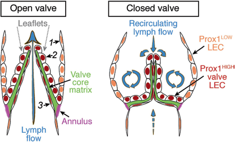
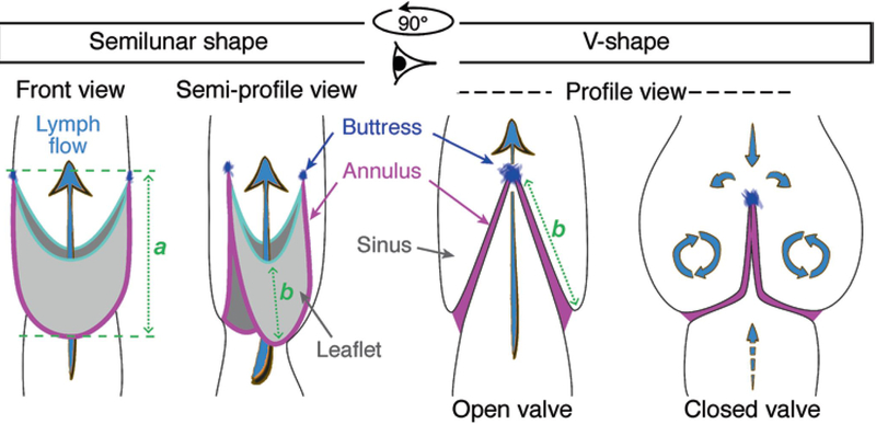
Lymphatic valves are semilunar bileaflet structures abundantly present in mature lymphatic collecting vessels (see Fig. 1). Each side of the leaflet is covered by a monolayer of lymphatic endothelial cells apposed on a thin sheet of specialized extracellular matrix. Lymphatic valves usually have two leaflets of the same size. The convex side of the leaflet is attached to the vessel wall, forming the valve annulus that is reinforced at the commissure by the valve buttress, while the semilunar part remains free and is oriented in the direction of lymph flow (see Fig. 1). Movement of lymph in the opposite direction pushes the valve leaflets together, and thus prevents retrograde flow. The main role of lymphatic valves is to direct, in concert with the pumping activity of lymphatic smooth muscle cells, the flow of lymph toward the draining lymph nodes in peripheral lymphatic vascular networks or toward the connection of central lymphatic vessels such as the thoracic duct or the right lymphatic duct with the blood circulation (reviewed in [4, 5]). Proper lymphatic valve organization and function is therefore indispensable for the functionality of the entire lymphatic system and failure of lymphatic valve development underlies human hereditary diseases of lymphatic vessels, such as lymphedema-distichiasis, caused by mutations in the transcription factor FOXC2 [6, 7].
Fig. 1.
Lymphatic valve organization and the associated lymph flow patterns. The leaflet is covered on both sides by Prox1HIGH LECs, which are more compact on the sinusal side subjected to recirculating flow and more elongated on the luminal side subjected to high laminar shear stress [1, 2]. A core of specialized ECM is sandwiched between the two layers of LECs. Leaflets are inserted within the vessel wall at the annulus, a fibrous circumferential fold rich in collagens and elastin, which changes shape during the valve cycle [3].
Collecting lymphatic vessels and valves are formed during late stages of embyogenesis in response to increased lymph flow [8]; this process continues during postnatal growth period and is reactivated during tissue regeneration [7, 9]. Previous studies established that valve LECs are molecularly distinct from lymphangion LECs [5, 7, 8, 10–13]. In particular valve LECs produce high levels of the transcription factors Prox1, Foxc2, Gata2, and Nfatc1 [8, 14], and the ECM components and integrin receptors laminin alpha5, FN-EIIIA, and Itga9 [11], which, together with other pan-endothelial markers such as PECAM1, can be used for the identification and characterization of lymphatic valve structures. Given the complexity of valve organization, visualization in 3D is mandatory for the assessment of eventual lymphatic valve phenotype, which is otherwise difficult if not impossible to characterize using conventional staining approaches on thin sections. Due to its flat structure, ease of preparation, and relatively stereotypic organization, the mouse mesentery became a tissue of choice for the analyses of lymphatic collecting vessel and valve organization [7, 8, 10, 11, 14, 15] (see Figs. 2 and 3).
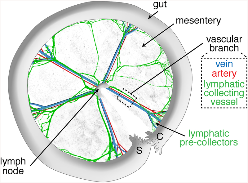
Fig. 2.
Scheme of a dissected anterior mesentery, unfolded clockwise from duodenum (Duo) to ileum highlighting its main components: intestine, mesentery, lymph node, and five vascular branches. The black dashed box indicates the vascular branch area selected for lymphatic vessel length and valve quantifications. The orange and pink dashed lines indicate the vascular branch segment that is selected for analysis of valves from collecting vessels and precollectors, respectively.
Fig. 3.
Bright-field pictures of a P6 neonate mesentery taken with a dissecting stereomicroscope. (a) Mesenteric loop. Mes mesentery, LN lymph node, In intestine. The red dashed box is magnified in (b). Scale bar: 5 mm. (b) Mesenteric vascular branch. Red arrowheads: lymphatic valves. The red dashed box is magnified in (c). Scale bar: 1 mm. (c) Lymphatic collecting vessel filled with milky chyle. Red arrows: lymphatic valves
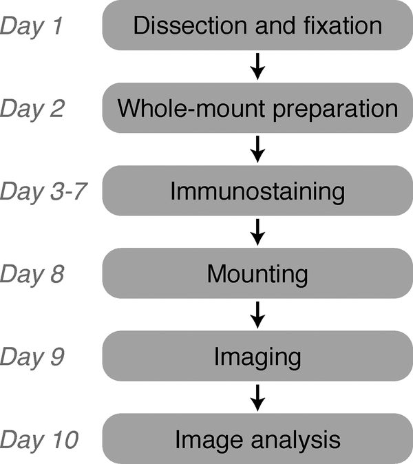
Here, we provide a protocol optimized for whole-mount analysis of the mesenteric lymphatic vessels of mouse pups at postnatal day 4–14 (see Fig. 4). A shorter version of this protocol is also provided for analysis of embryonic lymphatic vessels (see Note 1). Furthermore, as even morphologically normal lymphatic valves may be dysfunctional, we include a protocol for quantitative assessment of the mechanical properties of adult mesenteric valves using back-leak and closure tests.
Fig. 4.
Flowchart of the method for whole-mount staining and imaging of postnatal mouse mesentery
2. Materials
The procedure described can be used for mesenteries of mice up to P14. If mice are treated prior to mesentery collection, see Note 2. All procedures involving animal experiments should follow approved institutional and governmental animal protocols and comply with the relevant guidelines and regulations of the local animal ethics committee.
1. Dissecting microscope with reflected light illumination and a zoom magnification of at least 10×.
2. Dissecting board and needles (e.g., 26 G1/2, 0.45 × 12 mm).
3. Dissection tools: sharp straight surgical scissors (41 mm sharp edge, or more), microscissors (e.g., cutting edge: 5 mm), serrated forceps (e.g., tip: 1.3 × 1 mm), fine forceps (e.g., tip: 0.05 × 0.02 mm).
4. Stainless steel insect pins (e.g., Austerlitz Insect Pins, diameter: 0.2 mm; tip: 0.02 mm).
5. 70% ethanol spray.
6. 12-Well elastomer-coated cell culture plate. Coat wells with a thick (3–5 mm) layer of liquid elastomer (Sylgard® 184 Silicone elastomer kit, Dow Corning) and dry overnight under a fume hood.
2.1. Mice
The procedure described can be used for mesenteries of mice up to P14. If mice are treated prior to mesentery collection, see Note 2. All procedures involving animal experiments should follow approved institutional and governmental animal protocols and comply with the relevant guidelines and regulations of the local animal ethics committee.
2.2. Mesentery Dissection from Mouse Neonates
1. Dissecting microscope with reflected light illumination and a zoom magnification of at least 10×.
2. Dissecting board and needles (e.g., 26 G1/2, 0.45 × 12 mm).
3. Dissection tools: sharp straight surgical scissors (41 mm sharp edge, or more), microscissors (e.g., cutting edge: 5 mm), serrated forceps (e.g., tip: 1.3 × 1 mm), fine forceps (e.g., tip: 0.05 × 0.02 mm).
4. Stainless steel insect pins (e.g., Austerlitz Insect Pins, diameter: 0.2 mm; tip: 0.02 mm).
5. 70% ethanol spray.
6. 12-Well elastomer-coated cell culture plate. Coat wells with a thick (3–5 mm) layer of liquid elastomer (Sylgard® 184 Silicone elastomer kit, Dow Corning) and dry overnight under a fume hood.
7. PBS: dilute from a sterile stock of 10× PBS using autoclaved distilled water, store at 4 °C.
8. PBS-A: 0.1% sodium azide (w/v) dissolved in PBS (see Note 3), store at 4 °C. Sodium azide is a hazardous reagent; use a chemical fume hood and wear protective gloves and mask when preparing the solution.
9. 1 ml micropipette and corresponding tips.
10. Hazardous liquid waste container.
2.3. Mesentery Preparation for Whole-Mount Staining
1. Horizontal shaker at 4 °C.
2. 4% PFA: dissolve 4% paraformaldehyde (w/v) in PBS at 50 °C while stirring, filter using 0.45 μm filter and store aliquots at −20 °C. After thawing store at 4 °C and use within 7 days. Paraformaldehyde is a hazardous reagent; use a chemical fume hood and wear protective gloves and mask when preparing the fixative.
3. 10% sucrose solution: dissolve 10% d(+)-sucrose (w/v) in PBS-A with stirring, filter sterilize and store at 4 °C.
4. 20% sucrose solution: dissolve 20% d(+)-sucrose (w/v) and 10% glycerol (v/v) in PBS-A with stirring, filter sterilize and store at 4 °C.
2.4. Immunostaining
1. Blocking buffer: 0.5% bovine serum albumin (w/v), 5% donkey serum (v/v) (see Note 4) and 0.5% Triton X-100 (v/v) in PBS-A. Filter sterilize and store at 4 °C for maximum 3 months.
2. Washing buffer: 0.5% Triton X-100 (v/v) in PBS, store at 4 °C.
3. Primary antibodies (see Table 1).
Table 1.
Examples of lymphatic valve immunostaining and the list of antibodies used
| Antigen | Staining Lymphatic valve compartment | Other mesenteric components | Figure | Antibodies Reference | Concentration |
|---|---|---|---|---|---|
| Proxl | LEC nuclei: Valve leaflet cells ≫ Lymphangion cells | All LECs | Fig. 10b–d | R&D, #AF2727 | 1 μg/ml |
| Pecam-l | LEC membrane (enriched in cell-cell junctions) | All ECs | Figs. 9a and 10a | Clone MEC13.3; BD Pharmingen, #553370 | 1 μg/ml |
| VE-cadherir | 1 LEC membrane cell-cell junctions: Valve > Lymphangion | All ECs | - | R&D, #AF1002 | 1 μg/ml |
| Claudin-5 | LEC membrane cell-cell junctions | All ECs | Fig. 10c | Invitiogen, #34–1600 | 1 μg/ml |
| Podocalyxin | Glycocalyx: Valve ≫ Lymphangion | All vessels | Fig. 10b | Clone 192,703; R&D, #MAB1556 | 0.5 μg/ml |
| αSMA | vSMC cytoskeleton: Valve ≪ Lymphangion | Collecting vessels, arteries and veins | Fig. 9a | Clone 1A4; Sigma-Aldrich, #C6198 | 1 μg/ml |
| Collagen IV | Valve annulus ECM and valve basement membrane: Valve < Lymphangion | Basement membrane of all vessels | Fig. 9c | Millipore, #AB756P | 2 μg/ml |
| Laminin α5 | Leaflet core ECM | Basement membrane of lymphangions and blood vessels | Fig. 9b | See Refs. 8, 11 | |
| FN-EIIIA | ECM at the free edge of valve leaflet | Basement membrane of blood vessels | - | Clone FN-3E2; Sigma-Aldrich, F6140 | 1 μg/ml |
| Integrin α9 | Valve LEC membrane anchored to ECM: Valve ≫ Lymphangion | Arteries and veins, low in collecting vessels | - | R&D, #AF3827 | 0.5 μg/ml |
| Vegfr-3 | LEC membrane (endocytosed upon ligand binding): Valve ≫ Lymphangion | All LECs | - | R&D, #AF743 | 2 μg/ml |
4. Secondary antibodies (see Note 4).
5. P20 and P10 micropipettes, and corresponding tips.
6. Aluminium foil.
7. Stereomicroscope with epifluorescence illumination
2.5. Sample Mounting on Slides
1. Glass microscope slides (e.g., Thermo Scientific, 76 × 26 mm).
2. Glass coverslips (e.g., Menzel-Gläser, 24 × 24 mm, #1).
3. Adhesive spacers (e.g., diameter: 20 mm; depth: 0.12 mm deep).
4. Mounting medium with DAPI (e.g., ProLong Gold antifade reagent from Life Technologies).
5. P200 micropipette and corresponding tips.
2.6. Imaging and Image Analysis
1. Microscope with epifluorescence illumination (e.g., Zeiss Axiovision equipped with a Standard HBO arc lamp and Dapi, FITC, DsRED and Alexa 660 filter cubes).
2. Confocal microscope (e.g., Leica SP5 Tandem equipped with 3 lasers and confocal detection channels: 488, 543 and 633).
3. Image analysis software for confocal images (z-stack projection, 3D reconstruction, etc) (e.g., Imaris, Bitplane).
4. Image processing software (area, length, event and staining intensity measurement) (e.g., ImageJ, https://imagej.nih.gov/ij/).
2.7. Valve Function Analysis
See Chapter 15 for additional details.
1. Krebs solution supplemented with 0.5% BSA.
2. Sharpened forceps and microscissors.
3. Dissection chamber, recessed into table.
4. Fine wire for pinning.
5. Two glass micropipettes with tip diameters 30–50 μm and lightly fire-polished tips.
6. Two pipette holders with micromanipulator mounting system.
7. 12–0 monofilament suture or teased strands of 2–0 monofilament suture.
8. Two 10 ml syringes + 0.8 μm filters + two 3-way stopcocks + two 1 ft lengths of PE-190 tubing.
9. Dissection microscope, magnification range: 8–64×.
10. Dual fiber optic illuminator.
11. Heated perfusion chamber for ex vivo experimental studies.
12. Inverted microscope.
13. Bath perfusion pump.
14. Three low-pressure transducers and amplifiers.
15. Pressure control system.
16. Data acquisition interface, computer and controlling software.
17. Servo-nulling pressure measurement system. 18. Camera and diameter measurement system.
3. Methods
3.1. Lymphatic Valve Imaging
3.1.1. Mesentery Dissection
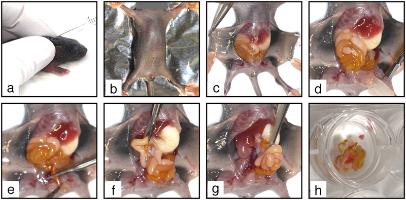
1. Euthanize the mouse pup by decapitation. Lay the body on its back on a dissecting board and stretch it flat by applying a needle in each limb (see Fig. 5b). Wipe the belly with 70% ethanol.
Fig. 5.
Mesentery collection procedure. (a) Tamoxifen is injected SC in the neck of a P6 mouse neonate. (b) The euthanized mouse is pinned on a dissecting board. (c) The abdominal skin is detached. (d) The peritoneum is removed to free the intestine. (e) The colon is cut above rectum. (f) The duodenum is cut under stomach. The intestine and mesentery are pulled out from the abdominal cavity (g) and transferred to PBS-A in a 12-well elastomere-coated plate (h)
2. Open the abdominal cavity with a small incision in the skin under the sternum. Insert one tip of the scissors between the skin and the abdominal wall. Open the skin by making a mid-line incision down to the pelvis. Make transverse incisions on both sides under the diaphragm and along the two hind limbs. Pin skin flaps to the dissecting board (see Fig. 5c).
3. Grab the abdominal wall with forceps and cut it open over the entire abdominal cavity (see Fig. 5d). Pay attention not to damage the internal organs during the procedure.
4. Push the intestines upward to get free access to the colon and cut it above the rectum (see Fig. 5e). Then, push the intestine downward to get free access to the duodenum and cut it below the stomach (see Fig. 5f). It is important that the intestine is completely severed at both extremities.
5. Insert serrated forceps in an open position under the intestine, from the stomach toward the pelvis, grab it from below (see Fig. 5g) and pull it out firmly to detach the mesenteric lymph node from underlying tissues.
6. Transfer the intestine to PBS-A in an elastomere-coated 12-well plate on ice (see Fig. 5h). It should be entirely covered with PBS-A to prevent drying.
3.1.2. Mesentery Pinning
Work under a dissection microscope for precise manipulation of the tissue. Mesentery should be pinned immediately after collection from the animal (see Note 5). Avoid directly grasping the mesentery with forceps to prevent tissue damage
1. Identify the duodenum and orientate the intestine to allow clockwise unfolding of the gut (see Note 6).
2. Pin down the duodenal extremity to the elastomere (see Fig. 6a).
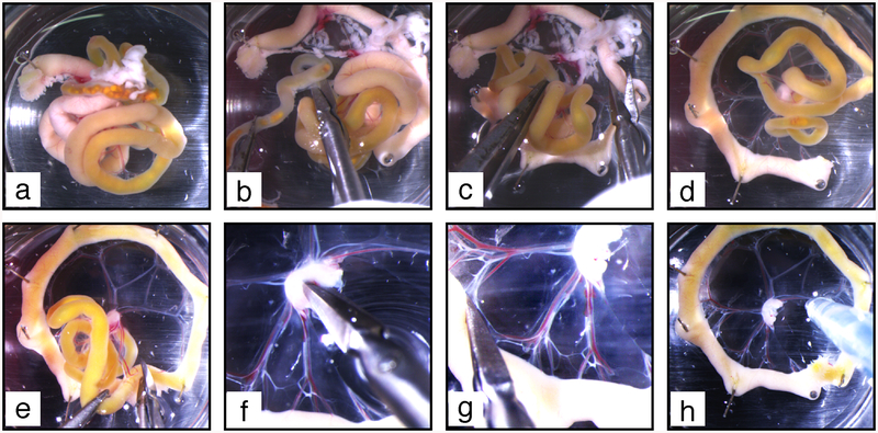
Fig. 6.
Mesentery dissection procedure. (a) The duodenum is pinned on elastomere to allow further clockwise unfolding of the intestine. (b) Clockwise unfolding gives access to the colon, which is excised above the caecum. (c) The pancreas (white diffuse tissue spread in the mesentery at the top of the image) is excised. (d) The mesentery is further unfolded to make a complete wheel. (e) The remaining part of the intestine is cut off. (f) The upper half of the lymph node is excised. (g) Small holes are made at the connection of each vascular branch with the intestine. (h) Blood and chyle are flushed out from mesenteric vessels
3. Progressively unfold the mesentery in clockwise direction by applying more pins, approximately at each bend of the intestine (see Fig. 6b–e). After inserting a pin half through the intestine at a bend, gently transport it away from the previous pin and from the mesenteric lymph node to sufficiently stretch the mesentery while avoiding rupture (see Note 7).
4. Identify the colon extremity, grasp it with forceps and cut the colon mesentery to detach it from the small intestine and mesenteric lymph node. Discard colon and caecum by cutting the intestine above the caecum (see Fig. 6b).
5. When the first wheel is half-completed, identify the pancreas located at the duodenal extremity as a soft and diffuse white tissue spread throughout the duodenal mesentery, partly attached to the mesenteric lymph node (see Fig. 6c). Using small scissors remove the pancreas by cutting the mesentery after the first vascular branch that follows the pancreas and discard it (see Note 8).
6. Continue unfolding the intestine and the mesentery to complete the wheel (see Fig. 6d).
7. Cut the mesenteric lymh node in two halves with microscissors; the anterior half will remain as the central “hub” of this first wheel, while the posterior half will constitute the “hub” of a second mesenteric wheel. Further cut the mesentery between two vascular branches, and eventually the intestine (see Fig. 6e). The posterior mesentery should detach entirely from the anterior one (see Note 9).
8. Once a wheel is complete, dissect out excess of tissues around the mesenteric lymph node and remove upper half of the lymph node using microscissors (see Fig. 6f) (see Note 10).
9. With microscissors, make small incisions in the mesentery at the end of each large vessel at the transition between the mesentery and the intestine (see Fig. 6g).
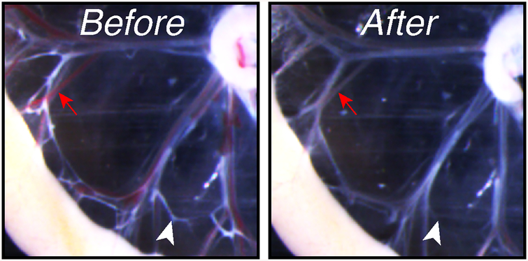
10. Replace PBS-A. 11. Using a 1 ml pipette, flush each vascular branch with PBS-A in lymph flow direction, i.e., from the intestine toward the lymph node (see Fig. 6h). Repeat until most blood and chyle are washed out from vessel lumens (see Fig. 7).
Fig. 7.
Mesenteric vessels before (left) and after (right) flushing with PBS-A. Red arrow: blood-filled vessel; white arrowhead: chyle-filled lymphatic vessel
12. Rinse twice with cold PBS-A and keep in PBS-A.
13. Between each mesentery, invert the plate over a liquid waste container and refill it with cold PBS-A.
14. When all mesenteries in a plate are prepared, rinse twice with cold PBS, and then replace PBS with cold 4% PFA under a ventilated hood. Plates with pinned mesenteries are kept on ice during the following procedure. All further incubations are done at 4 °C on a rotating platform. Attention should be paid not to allow tissues to dry up (see Note 11).
3.1.3. Mesentery Preparation for Immunostaining
1. Fix mesenteries for 6 h.
2. Under a ventilated hood, discard PFA and replace it with cold PBS (see Note 12).
3. Rinse three times with PBS, then wash 3 × 20 min with PBS-A.
4. Incubate for 2 h in 10% sucrose solution (see Note 13).
5. Incubate for 2 h in 20% sucrose solution (see Note 13).
6. Rinse three times with PBS, then wash 3 × 1 h with PBS-A.
7. Tissues can be stored in PBS-A at 4 °C up to 3 months.
3.1.4. Immunostaining
1. Rinse tissues twice with PBS-A (see Note 14).
2. Incubate for at least 8 h with blocking buffer.
3. Prepare the mix of primary antibodies in blocking buffer (see Table 1) and store it on ice. Enough mix should be prepared to allow complete immersion of the samples (e.g., 1 ml per well in a 12-well plate).
4. Rinse tissues once with blocking buffer to remove any floating tissue pieces.
5. Add primary antibody mix, making sure that the tissue is completely immersed.
6. Incubate overnight.
7. Discard primary antibody mix one well after another to prevent mixing antibodies (see Note 15), and wash 5 × 1 h with washing buffer.
8. Prepare secondary antibody mix in blocking buffer (see Note 16). Keep away from light.
9. Add secondary antibody mix, filling one well after another to prevent drying of tissues. Wrap the plate with aluminium foil to protect from light, from this step on.
10. Incubate overnight.
11. Discard secondary antibody mix (see Note 17) and wash 3–10 times for 30 min with washing buffer. The number of washes is antigen- and antibody-dependent. Check the staining after three washes using a fluorescent stereomicroscope to decide whether additional washes are necessary. If background staining of the surrounding tissues is high, up to ten washes can be done. If the specific staining is low, stop after five washes.
12. Rinse twice with PBS and refix for 2 days with 4% PFA (see Note 18).
13. Rinse 3 times with PBS, then 3 × 1 h with PBS-A. Tissues can be kept for up to 1 month in PBS-A at 4 °C away from light before mounting without loss of quality (see Note 19).
3.1.5. Tissue Mounting on Slides
1. Rinse tissues once with PBS.
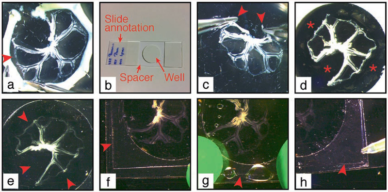
2. Under a dissection microscope remove the intestine using microscissors, cutting as close as possible to the gut wall (see Fig. 8a). Discard the intestine and the pins.
Fig. 8.
Procedure of mesentery mounting on microscopy slide. (a) The intestine is cut off the mesentery at the junction between the two. Arrowhead: detachment of the mesentery (b) Microscopy slide is prepared with a central spacer. Mesentery is grasped at the two external extremities (arrowheads) (c) and transferred to the slide within the spacer well, when the opaque liner is still present (d). Asterisk: empty well. (e) Opaque liner is removed and mesentery is covered with mounting medium to fill in the spacer well. Arrowheads: well filled with mounting medium. A coverslip (arrowhead) is applied to a sticky border of the spacer (f), let to fall on the mesentery and tightly attached to the spacer (g). (h) Mounting medium is added to remove air bubbles under the coverslip
3. Rinse mesenteries three times with PBS to remove traces of sodium azide.
4. Prepare slides with spacers. To place a spacer (see Note 20 and Fig. 8b) remove the transparent liner from the spacer without touching the adhesive, attach the spacer at the center of the slide as flat as possible, eliminate air bubbles first by applying a firm pressure with your finger on the thick opaque liner on each side, then using a dissection tool (e.g., scissors) as a roller to ensure complete adhesion to the slide. Mark the slides.
5. Seize the mesentery at the two extremities using two forceps (see Fig. 8c) and transfer it on the slide in the same orientation (see Note 21).
6. Under the stereomicroscope unfold the mesentery using closed forceps. Touch tissue as little as possible to avoid damaging the vessels (see Note 22).
7. When the mesenteric wheel is unfolded flat on the slide (see Fig. 8d), drain the excess of PBS with a tissue paper. Remove the thick opaque liner.
8. Quickly add 3 drops of mounting medium containing DAPI on top of the mesentery (see Note 23).
9. Gently tilt and rotate the slide to fill in entirely the room delimited by the spacer (see Fig. 8e). Remove all air bubbles using a 200 μl pipette.
10. Under the microscope, raise each of the two mesentery extremities to allow mounting medium to flow beneath. Carefully replace the mesentery in the wheel position. Add a new drop of mounting medium on top of the mesentery.
11. Apply a coverslip by placing one of its borders to the spacer and letting coverslip fall on the mesentery (see Fig. 8f). Quickly apply pressure with fingers on the coverslip borders to ensure adhesion to the spacer (see Fig. 8g).
12. Gently release the pressure on the coverslip while, if necessary, adding more mounting medium using a 200 μl pipet to prevent the formation of bubbles (see Fig. 8h).
13. Release completely the pressure. Check that all four borders of the coverslip are attached to the spacer.
14. Store the slide in a horizontal position at 4 °C for 24 h to allow polymerization of the mounting medium.
15. Control the absence of air bubbles under the coverslip and refill with mounting medium if necessary (see Note 24). Slides can be kept at 4 °C for up to 4 weeks without loss of fluorescence (see Note 25).
3.1.6. Valve Imaging and Analysis
The number and size of valves varies depending on the collecting vessel location in the mesenteric vasculature; therefore, the anterior and posterior mesenteries are analyzed separately. Careful mapping within the mesentery at low magnification (see Notes 26 and 27) and examination at high magnification are necessary to allow optimal selection of valves for quantification and unbiased comparison (see Table 2).
Table 2.
Examples of applications and criteria of fluorescent microscopy imaging of mesenteric lymphatic valves. Illustrations are shown in Figs. 9 and 10. n.a. not applicable (High-magnification imaging of valves necessitates confocal microscopy, due to their multilayered organization.)
| Imaging techniques and AIMS | Microscope | ||
|---|---|---|---|
| Epifluorescence | Confocal fluorescence | ||
| Magnification (objective) | 10–20× |
|
|
| 20–40× |
|
|
|
| >40× | n.a. |
|
|
1. Quantification of lymphatic valve number. This analysis is done with mesenteries stained for Prox1.
(a) Imaging. Using epifluorescence microscope take a tiled picture of the entire mesenteric wheel comprising 3–5 vascular branches (see Note 28). If tiling is not an option, take a picture of three entire vascular branches per mesentery (see Fig. 2).
(b) Lymphatic vessel length. Using ImageJ software, adjust the image levels to visualize all Prox1+ LECs. Determine the lymphatic vessel length of each branch by using the segmented line tool and measure action. Calculate the total lymphatic vessel length by adding up the data for all branches analyzed. (c) Number of valves. Using ImageJ software, adjust the image levels to visualize Prox1HIGH valves and Prox1LOW lymphangions. Quantify manually the number of valves (Prox1HIGH regions) for each branch. Calculate the total number of valves by adding up data for all branches analyzed. (d) Graph. Plot the total number of valves per total lymphatic vessel length (mm) (see Note 29).
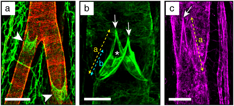
2. Quantification of valve size and leaflet length. This analysis is done with mesenteries costained for Prox1 and a leaflet marker such as an ECM component laminin alpha5 (Lama5) (see Fig. 9b), an adhesion receptor to the core matrix such as integrin alpha9 (Itga9) or a constituent of the glycocalyx that accumulates in high-shear regions such as podocalyxin (see Fig. 10b).
Fig. 9.
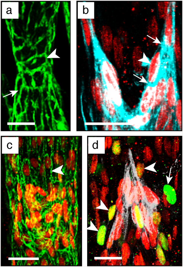
Examples of mesenteric lymphatic vessels and valve ECM stainings. (a) Collecting vessel bifurcation stained to analyze its coverage by mural cells. Pecam1 in green, alphaSMA in red. Scale bar: 100 μm. (b) Valve leaflet core matrix stained for laminin alpha5. Scale bar: 30 μm. (c) Valve matrix stained for collagen IV. Scale bar: 50 μm. Arrowhead, lymphatic valve devoid of mural cells; arrow: valve buttress; asterisk: luminal free edge of the valve leaflets; (a) valve length; (b) leaflet length
Fig. 10.
Imaging of valve LECs. (a) Valve stained for Pecam1 to show valve cell shape. Arrow: elongated cell; arrowhead: rounder valve cell. Scale bar: 20 μm. (b) Valve cells stained for Prox1 and podocalyxin to highlight the sinusal free edge of the valve leaflets. Arrowhead: Prox1HIGH cell at the free edge; arrows: increased deposition of podocalyxin at the free edge. Scale bar: 20 μm. (c) Staining for Prox1 and claudin5 to show intercellular junctions (arrowhead) between valve cells. Scale bar: 25 μm. (d) Valve cell proliferation showed by staining for Prox1 and Ki67. White staining: Lama5. Arrowhead: proliferating Ki67+/Prox1HIGH valve cell; arrow: proliferating Ki67+/Prox1LOW lymphangion cell; asterisk: Ki67+/Prox1neg proliferating non-LEC. Scale bar: 20 μm
(a) Valve selection. Given that Lama5, Itga9, and podocalyxin antibodies also stain blood vessels, select valves that do not overlap with the blood vasculature (see Fig. 2).
(b) Imaging. Using a confocal microscope take a 40×-picture of the valves in an orientation that allows clear distinction of the leaflets (see Fig. 11 and Note 30). Acquire 3–5 pictures per mesentery.
Fig. 11.
Overview of different possible valve appearances, under the microscope and on 2D pictures, depending on their orientation and opening/closure status. Blue arrows show lymph flow direction. The main valve component, which can help in their orientation (sinus, annulus, buttress and leaflet) are depicted. (a) Valve length; (b) leaflet length
(c) Reconstruct each valve as a 2D z-stack picture using ImageJ or Imaris softwares and export the image, e.g., as a TIFF file.
(d) Exclusion of precollectors. Using ImageJ software, discard the outer one-third of the mesentery, as it comprises most precollectors (see Fig. 2 and Note 31).
(e) Valve length. Using ImageJ segmented line tool and measure action measure the valve length, defined as the vessel portion associated with high levels of Prox1 and Lama5/Itga9/podocalyxin (indicated as “a” in Fig. 11). This quantitative measure can be useful when there is almost complete degeneration of leaflets.
(f) Leaflet length. Select one z-slice layer from the z-stack (e.g., using the slice view tool of Imaris) that shows at the same time the most external sinus margin of the valve annulus and the free edge of the corresponding leaflet. Export the corresponding image to ImageJ and measure the leaflet length, (indicated as “b” on Fig. 11). (g) Graph. Calculate the averaged valve and leaflet lengths to obtain an average value for one animal (n = 1).
3. Analysis of lymphatic valve endothelial cells. This analysis is done with mesenteries costained for Prox1 and other markers of your choice (see Note 32). Analysis of valve cell proliferation using Ki67 as a marker of cell proliferation is described below (see Fig. 10d).
(a) Imaging. Under a confocal microscope, take a 40×-picture of the well-defined valves that are located away from the blood vessels. Collect 3–5 pictures per mesentery. Lymphatic valves should be selected as described above (see above steps 1 and 2).
(b) Reconstruct each valve as a 3D picture using Imaris software. Export the 2D z-stack image as an illustration (e.g., TIFF file).
(c) Proliferating valve cells. Using the 3D view tool of Imaris, by rotating and magnifying the 3D image, identify and count the double-positive Prox1HIGH/Ki67+ cells (see Fig. 10d and Note 33).
(d) Data analysis. The number of proliferating valve cells per valve can be averaged for all valves to obtain a mean value per animal. Alternatively, given the low number of proliferating valve LECs, normalize the total number of Prox1HIGH/Ki67+ cells to the number of valves that have been analyzed. For both measurements, a single value per animal should be used for statistical analysis.
3.2. Lymphatic Valve Function Analysis
Dissect and cannulate a mouse lymphatic vessel using the methods described in Chap. 15; for mesenteric lymphatics use the protocol described for popliteal afferent lymphatics with the following variations.
3.2.1. Mesenteric Vessel Dissection
1. After the mouse is anesthetized and has reached a surgical plane of anesthesia, make a midline incision in the abdomen, about 2 cm long.
2. Turn the mouse on its side and exteriorize a 5–6 cm loop of intestine, preferably duodenum.
3. Pin it to a Sylgard platform using 00 insect pins. The dissection and cannulation steps will be much easier if the vessel is filled with chyle, which is more likely to be present if the animal has eaten or been gavaged with olive oil 30–60 min prior to surgery.
4. Locate an appropriate segment containing 2–4 valves (see Fig. 3b); the larger diameter vessels in the central arcades near the root of the mesenteric node will be easiest to cannulate.
5. Remove the surface fat with the coarse microscissors, being careful not to cut too close to the vessel wall.
6. Cut the thin layer of mesothelium along each side of the vessel and then cut each vessel end, starting with the proximal end first to increase the likelihood of retaining chyle in the lumen.
7. Transfer the vessel to a Sylgard dissection dish filled with Krebs-BSA solution (see Chap. 15) and pin it down using short pieces of 40 μm stainless steel wire.
8. Under pseudo-oblique illumination (see Chap. 15) carefully remove most of the fat, especially at the two ends. It is usually best not to remove all the fat until the vessel is cannulated and pressurized.
9. Transfer the vessel to the cannulation chamber, filled with Krebs-BSA solution, with prefilled cannulation pipettes, all mounted to a portable stage (see Chap. 15). Keep the vessel from floating during cannulation by weighing one end down with a 1–1.5 cm long piece of 40 μm wire.
3.2.2. Cannulation and Cleaning
1. Cannulate the input end as described in Chapter 15.
2. Tease open the output end using the cannulation forceps and temporarily raise the inflow pressure from 3 to 10 cm H2O for 30 s to flush out the lumenal contents.
3. Return the inflow pressure to 3 cm H2O and cannulate the outflow end of the vessel.
4. Once both ends are cannulated and pressurized to 3 cm H2O, increase the axial length until there is no lateral bowing and use the 45° angled cannulation forceps and fine microscissors to remove the remaining fat. Be particularly careful near the fragile valve sinuses.
5. Once the fat is removed the vessel should be shortened to one valve for valve tests. Starting with a segment that contains 2–3 valves provides flexibility in the event that one part of the vessel wall is accidently nicked or damaged during cleaning.
6. If all valves are intact and the wall is undamaged the easiest way to shorten to one valve is to loosen the tie on the inflow pipette and advance it through the appropriate number of valves, leaving a single valve near the outflow pipette. The inflow pipette can only be advanced ~500 μm at a time (depending on the taper angle of the pipette) and will retract unless it is retied. After retying, cut the vessel off around the shank of the inflow pipette before advancing it further. Repeat this procedure of advancing and cutting as necessary to obtain a one-valve segment. Be sure to leave a reasonable length of vessel (200–300 μm) for micropuncture on the input side of the remaining valve.
3.2.3. Valve Orientation
1. Rotate the vessel so that both valve leaflets are visible, with the valve buttresses [16] on the top and bottom surfaces (“V-shape” in Fig. 11). To rotate it, loosen the suture at one end and turn the vessel by pulling gently on its two sides behind the loose tie. Retie it and repeat this step at the other end. (If only one end is rotated in an attempt to orient the valve the vessel likely will twist during subsequent protocols as outflow pressure is raised, so rotate the vessel only ½ way at each end).
2. Carefully remove any remaining mesothelium, fat or connective tissue along the inflow end of the vessel, paying particular attention to the top surface of the vessel near the pipette where the wall will be micropunctured.
3. Secure the ties and transfer the vessel, pipette assembly, and cannulation chamber to the stage of an inverted microscope (see Chapter 15).
3.2.4. Vessel Perfusion
1. Disconnect the syringe lines from the back ends of the cannulation pipettes/holders and connect them to a water-filled, adjustable reservoir system (see Chapter 15) set to 3 cm H2O. Make sure that one port of the 3-way stopcock is open to atmosphere when disconnecting or connecting each line.
2. Connect the water bath to the water jacket of the cannulation chamber.
3. Begin perfusing the chamber with Krebs at 0.5 ml/min and allow the vessel to equilibrate to 37 °C for 30–60 min. Mesenteric vessels will develop small amplitude vasomotion but not spontaneous contractions [17]. Mesenteric valve tests can therefore be conducted in Krebs solution, but the contractions of lymphatics from other regions must be stopped for valve tests by perfusion with Ca2+-free Krebs solution.
4. Calibrate the pressure transducers by connecting them through a T-connector to a single, adjustable reservoir to ensure that both the inflow and outflow pressure transducers (and the servo-nulling pressure transducer) are calibrated to within 0.1– 0.2 cm H2O of each other (see Note 34).
5. Switch the 3-way valve so the pressure controller is connected to the cannulating pipettes (see Note 35).
3.2.5. Vessel Micropuncture
To measure pressure on the inflow side of the valve, use a servo-nulling micropressure system with a sharp micropipette broken back to a 3 μm tip (see Note 36). The pump, line, and holder should be prefilled with 2 M NaCl and all air bubbles removed.
1. Raise both pressures to 10 cm H2O, remove any axial slack, if present (a taut vessel is easier to micropuncture).
2. Using the servo-nulling pipette to make the micropuncture hole will usually plug up the micropipette, so first use a pilot pipette—an unfilled micropipette made of the same glass with a sharper taper and fine point (unbroken)—to make a small hole in the vessel wall. Puncturing the wall near the inflow cannulation pipette will be easier than in the middle of the vessel because the cannulation pipette will anchor it and help prevent bowing during micropuncture. During this procedure temporary use of a higher magnification objective (e.g., 16×) allows better visualization of the micropuncture hole than a lower magnification objective (e.g., 4 or 6.3×) routinely used during the valve test protocols.
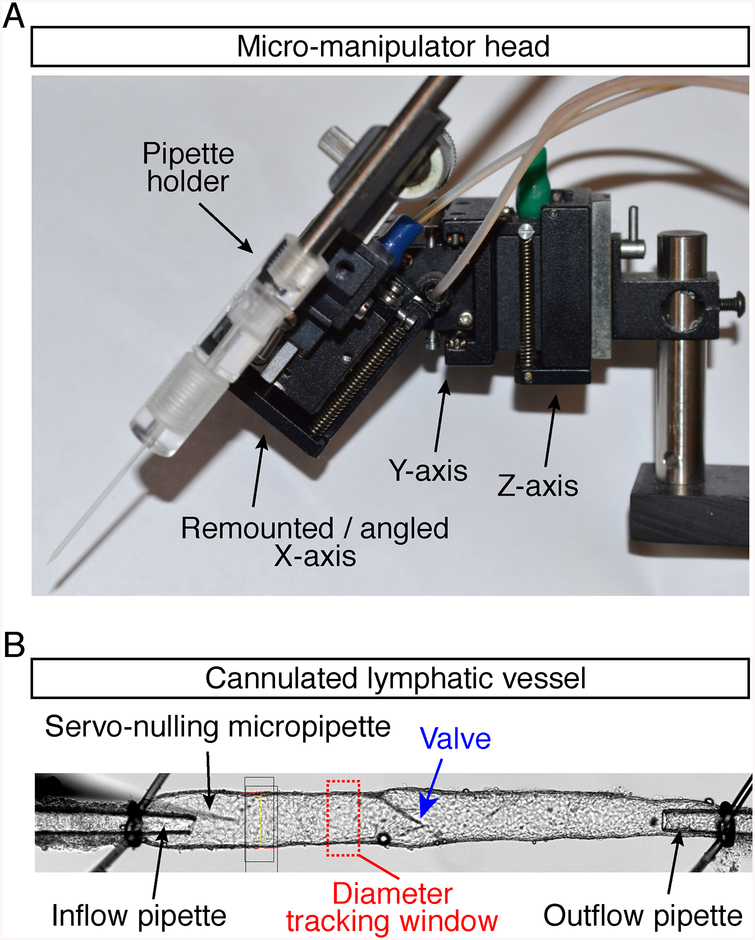
3. Mount the pilot pipette in a holder at a 45° angle to the vessel (see Fig. 12a and Note 36).
Fig. 12.
(a) Rear view of converted x-axis (moved to 45° angle) of Narishige M102 micromanipulator head (pipette holder is on back side). (b) Bottom view of inflow, outflow and servo-nulling pipettes, showing their positions relative to the cannulated lymphatic vessel
4. Make a small indentation in the vessel wall (top surface) by lowering the pipette in the Z-axis.
5. Rapidly thrust the pipette forward for ~100 μm using the 45° axis control; it should push easily through the wall.
6. Pull back slightly on the control for that axis and also lift the micropipette slightly in the Z-axis so that the tip is centered in the vessel lumen; slide it in and out using the 45° axis control, pushing it a bit further into the lumen each time to widen the pilot hole to ~5–10 μm.
7. After memorizing the location of the hole (see Note 37), withdraw the pilot pipette completely, raise it out of the bath solution, and replace it with the 2 M NaCl servo-nulling pipette.
8. Lower the servo-nulling pipette next to (but outside of) the vessel, confirm that the tip is clear (see Note 38), turn up the servo null gain, and adjust the offset to read zero (see Note 39).
9. Use the manipulator controls to carefully guide the servo-nulling pipette back into the hole made by the pilot pipette: once the tip is centered in the hole, lower it in the Z-axis and then advance it at a 45° angle. As soon as the servo-nulling micropipette enters the lumen the readout on the servo-nulling pressure transducer (Psn) should be 10 cm H2O. If it is [Fig 12 here] slightly high or low, adjust the balance control of the servo-null system so that the Psn readout is 10 cm H2O (see Note 39).
10. Advance the micropipette into the lumen until the shank of the micropipette wedges into the pilot hole, sealing the hole (see Fig. 12b).
11. Raise the tip in the Z-axis as necessary to keep the tip clear of the endothelium.
12. Adjust the set pressures on the controller for both inflow (Pin) and outflow (Pout) pressures to 0.5 cm H2O; the servo-null reading should drop immediately to 0.5 cm H2O. If the reading is high or low adjust the offset control of the Psn amplifier; then again raise pressure to 10 cm H2O and if the servo-null reading is not exactly 10 cm H2O, adjust the gain slightly.
13. Set the pressure to 0 and then 10 cm H2O, check the values and repeat if necessary until you are confident of the calibration.
3.2.6. Back-Leak Test
This test measures the degree of pressure back-leak through a closed valve when outflow pressure is raised [7].
1. Set both Pin and Pout to 0.5 cm H2O.
2. Using an appropriate computer program to drive the pressure controller, initiate a ramp-wise increase in Pout from 0.5 to 10 cm H2O (rate ~8 cm H2O/min) while Pin is held at 0.5 cm H2O. A normal valve should close before Pout reaches ~2 cm H2O; if it does not, then tap gently on the Pout line to encourage closure.
3. When Pout reaches 10 cm H2O, return it to 0.5 cm H2O and repeat the test twice.
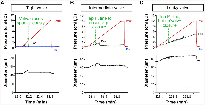
4. For analysis, take the average of the three final servo-null pressures recorded when Pout reaches 10 cm H2O. A value of 0.5 cm H2O is used for Pin because it is low enough that a normal valve will easily close, but not so low that the vessel partially collapses and touches the tip of the servo-nulling micropipette. See examples of the behavior of normal, abnormal, and intermediate valves in Fig. 13. For a normal valve the average Psn value when Pout reaches 10 cm H2O should be 0.5 cm H2O (i.e., no back-leak); for a completely incompetent valve the servo-null reading should be ~5.2 cm H2O (approximately ½ between 0.5 and 10 cm H2O, but will depend both on the position of the valve, i.e., if the valve is exactly midway between the two cannulating pipette tips, and the position of the servo-null pipette relative to the valve, i.e., if the Psn [Fig. 13 here] there will be backflow through it and therefore a continuous pressure drop along the length of the vessel toward the inflow pipette. It is important to be sure that no debris has accumulated on the cannulating pipette tips, particularly the inflow pipette tip during this procedure, or the measurements will be invalid. Be sure the servo-nulling micropipette tip does not contact the vessel wall during the Pout ramp (some vessel bowing may occur); doing so will produce an artifactual rise in the Psn reading that can be corrected by adjusting the micropipette tip position. Check the calibration of the Psn pipette by stepping both Pin and Pout from 0.5 to 10 cm H2O and back again (see Note 39). If the pipette calibration is off, then correct it by adjusting the offset/gain controls of the Psn amplifier, or change the pipette and repeat the test(s).
Fig. 13.
Valve back-leak test. Experimental traces showing Psn recordings during back-leak tests on normal (a), intermediate (b), and abnormally leaky valves (c). Pin: inflow pipette pressure; Pout: outflow pipette pressure; Psn; servo-nulling micropipette pressure
3.2.7. Valve Closure Test
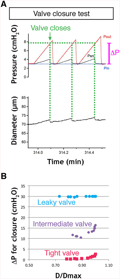
This test measures the adverse pressure gradient required to close a valve; the value will vary as a nonlinear function of the passive vessel diameter, which in turn is determined by the baseline pressure in the passive vessel [3].
1. Set Pin and Pout to 0.1 cm H2O.
2. Note the value of the vessel diameter (see Note 40).
3. Increase Pout ramp-wise to ~30 cm H2O at a rate of ~8 cm H2O/ min while watching the valve leaflet positions and/or Psn reading. Psn will rise with Pout, but when the valve snaps shut Psn will fall back rapidly to 0.5 cm H2O if there is no back-leak through the valve. (If there is some back-leak then the Psn reading will be commensurately higher than 0.5 cm H2O.) A normal valve will close at Pout < 2 cm H2O (or even < 0.5 cm H2O) when Pin is 0.1 cm H2O.
4. Note the value of Pout when the valve closes (see Fig. 14a and Note 41). A completely incompetent valve may never close even when Pout exceeds 30 cm H2O.
Fig. 14.
Valve closure test. (a) Experimental traces showing changes in Pin, Pout and Psn pressures before, during and after closure of a normal valve in response to a Pout ramp (repeated twice). The vessel diameter does not return to its original level in the time period shown, due to the viscoelastic properties of the vessel wall. (b) Plot of ΔP at point of valve closure vs normalized vessel diameter for complete sets of valve closure tests on a normal (tight) valve, a valve with intermediate behavior, and a defective (leaky) valve, which never closed during the tests. The valve might close at higher Pout levels but the maximal Pout levels are kept under 40 cm H2O to prevent damage to the low-pressure transducers
5. Repeat this test twice and take the average of the Pout values at which the valve closed.
6. Set Pin and Pout to 0.2 cm H2O and repeat the Pout ramp to 30.2 cm H2O.
7. Repeat twice, noting the initial vessel diameter each time. 8. Repeat this sequence for initial pressure levels of 0.1, 0.2, 0.3, 0.5, 1, 2, 3, 5, 8, 10 cm H2O (with the final Pout ramp to 40 cm H2O). The relationship between the pressure difference required to close the valve (“ΔP” in Fig. 14a) and the normalized vessel diameter (D/Dmax) for all of the data points will be similar to that shown in Fig. 14b. Obtaining data to generate a complete curve will provide a more complete assessment of the ability of the valve to close than will a single measurement.
3.2.8. Cleanup
1. Withdraw the Psn pipette from the vessel and turn off the servo-nulling system gain before raising the pipette out of the solution.
2. Remove the pipette from the holder and discard the pipette.
3. Flush the line and pipette with distilled H2O.
4. Disconnect the pressure controller from the inflow and outflow pipette holders.
5. Disconnect the water bath and perfusion tube.
6. Transfer the chamber with pipette assemblies to the dissection scope.
7. Untie the vessel ends.
8. Remove, clean, and store the cannulation pipettes (see Note 41).
9. Clean the chamber and pipette holders (see Chap. 16).
4. Notes
4.1. Lymphatic Valve Imaging
1. Analysis of embryonic mesenteric vasculature. (a) As there is no chyle in embryonic lymphatic vessels, do not make small incisions at each connexion of the vascular branches to the gut (steps 3.1.2.9–11). (b) Fix embryonic mesenteries for shorter time, i.e., 2–6 h (steps 3.1.3.1). (c) Do not equilibrate embryonic mesenteries in sucrose solutions (steps 3.1.3.4–6). (d) Leave the intestine attached to the mesentery (steps 3.1.5.1–2) and use it during the mounting procedure for transferring the sample to the slide (step 3.1.5.5) and for repositioning of mesenteric “wheel” (step 3.1.5.6).
2. Mouse treatment prior to mesentery collection. Intraperitoneal injections of oil-based solutions should be avoided as they can induce angiogenesis, influx of immune cells, and fat deposition. It is recommended to inject drugs subcutaneously, e.g., in the neck of the mouse (see Fig. 5a).
3. As a bacteriostatic agent, sodium azide preserves tissue integrity and is especially important here to limit damages caused by gut contents.
4. We use donkey serum and secondary donkey antibodies and perform triple fluorescent immunostaining using Alexa Fluor 488-, 555-, and 647-conjugated secondary antibodies.
5. This will limit modifications of the vessel and valve structures because of tissue stretching. The time between mesentery dissection and fixation should be as short as possible.
6. The clockwise unfolding of the intestine is easier and minimizes damages caused by tissue stretching.
7. Excessive tissue stretching will lead to detachment of the mesentery from the intestine, while insufficient stretching will produce a difficult to image “wrinkled” mesentery.
8. It is important to excise entirely the pancreas as pancreatic enzyme activity may affect the quality of staining.
9. The posterior mesentery is either discarded as it contains fewer valves, or pinned down in a second wheel following the same procedure.
10. To reduce thickness of the tissue due to protruding lymph node, cut off the upper half of the lymph node.
11. Do not allow tissues to dry up as this will greatly reduce the quality of staining and lead to high background.
12. Proceed one well at a time to replace PFA with PBS to prevent tissues from drying up.
13. Sucrose penetration in the tissue preserves cellular morphology during the permeabilization process. Incubation in sucrose solutions can be extended up to 24 h without quality loss; however, do not exceed 24 h to avoid bacteria growth.
14. If necessary, fixed mesenteries can be unpinned from elastomere, transferred to another well and repinned before proceeding to immunostaining. However, the procedure might damage the tissue structure and should be avoided if possible.
15. Primary antibody mixes can be recovered after overnight incubation, stored at 4 °C and reused several times. Not all primary antibodies are reusable; this feature should be tested first.
16. Secondary mix should be diluted according to the manufacturer’s indications, e.g., Alexa-conjugated antibodies from Life Technologies provide good quality of detection when diluted at 4 μg/ml.
17. Secondary antibodies cannot be reused in our experience.
18. Refixation of mesenteries after immunostaining allows longer storage. It also hardens the tissue and facilitates mesentery mounting on slides.
19. Do not exceed 1 month of storage prior to mounting samples as background fluorescence increases with time. It is recommended to replace PBS-A with fresh buffer once a week to prevent bacteria growth.
20. A spacer is a thin double-sided adhesive layer that delimits a 3D chamber to enclose the sample without compressing it. Multiple spacers can be combined for thicker tissues. Spacers allow 3D imaging of lymphatic valves with minimal structural distortion.
21. It is important to ensure correct orientation of the mesentery as the two sides are not equivalent. Position of the lymph node discriminates between the two sides: it should lie on the mesentery rather than under it (see Fig. 2).
22. Grasp the mesentery from its border—formerly attached to the intestine—to pull and unfold the tissue. Mesentery refixation before mounting greatly facilitates this step (see Note 18).
23. This step can be replaced by an incubation of mesenteries with a DNA staining solution (e.g., 500 ng/ml DAPI in PBS) for 10 min prior to mounting tissues.
24. If a bubble has formed under the coverslip apply a gentle pressure on the bubble to eject it, while adding a drop of mounting medium at the site of air ejection. Release the pressure to allow aspiration of the mounting medium that will refill the space under the coverslip.
25. Quality of confocal imaging is higher when slides are processed in the week that follows the mounting.
26. Vascular branch selection. Equivalent mesenteric vascular branches should be compared between samples (see Fig. 2).
27. Lymphatic valve selection. It is crucial to compare or quantify equivalent valves within and between samples (see Fig. 2). (a) Valves are bigger near the lymph node than in the vicinity of the intestine. (b) Valves are more numerous in the smaller vessels close to the intestine than in the lymph node afferent collecting vessels.
28. As mesentery dissection procedure often damages borders of the mesentery, the two external branches of the mesentery should be excluded from the analysis (see Fig. 2).
29. It is also possible to plot the mean number of lymphatic valves per vascular branch. Equivalent branches should be then compared between animals.
30. Valve orientation. Valves in similar phases of the opening/closure cycle [1, 2] and orientation angle should be selected for analysis for leaflet length measurement (see Fig. 11).
31. Collecting vessel valves are larger and have a more complex organization in comparison to precollector valves found near the gut wall (see Fig. 2).
32. Markers selected for valve cell phenotype analysis are often not specific to LECs (e.g., Ki67) (see Table 1). It is therefore important to identify valve LECs using Prox1 staining to exclude the other cell types from analysis, e.g., by generating a Prox1+/Ki67+ mask channel with Imaris software: (a) In the 3D view add a surface for Prox1+ nuclei by adjusting the threshold to select only Prox1HIGH cells. (b) Using the Edit tool of Prox1 surface select Ki67 channel. (c) Adjust Ki67 threshold to select only Ki67 staining that overlaps with Prox1 surface. (d) Duplicate channel before applying mask.
33. It is important to adjust the detection gain for Prox1 staining during image acquisition to allow clear distinction between Prox1LOW lymphangions and Prox1HIGH valves. Too low signal will prevent lymphangion visualization, whereas too high signal detection will complicate valve distinction from lymphangion.
4.2. Lymphatic Valve Function Analysis
34. Pressure transducers. We use CyQ model 104 low-pressure interfaces and 304 low-pressure displays (Nicholsville, KY) for inflow, outflow and servo-nulling pressure measurements. As the company is no longer in business an alternative amplifier/ display is a model DP41-B-A general purpose amplifier from Omega Engineering (Stamford, CT) with an appropriately wired low-pressure transducer element such as a Honeywell MPX-2010GP board mount pressure sensor (Mouser Electronics), which is linear and accurate at low pressures but cannot withstand sustained pressures >50 cm H2O (the same element is used by the CyQ amplifier). Other low-pressure sensors will work and newer models (e.g., Honeywell HSC series) may be even more accurate and/or linear. The Omega amplifier “model B-A” has an A–D output to interface with a computer data acquisition device; we use a USB-2616 BNC interface (National Instruments, Austin, TX) connected to a Dell computer running custom LabVIEW programs (National Instruments) under Windows 7 [24].
35. Pressure controller. A moveable reservoir system is preferable for initial set up and calibration, but a computer-controlled pump (e.g., microfluidic reservoir) is needed to generate rampwise pressure steps for valve tests. Connect the outflow line of each reservoir to one port of a 3-way valve (HPLC-grade; Hamilton, Reno NV); connect the outflow line of the computer- driven pump to the second port of the 3-way valve; connect the third port of the valve to the tubing leading to the pipette holder of one cannulation pipette. Repeat this procedure for the second reservoir, pump, 3-way valve, and cannulation pipette. Commercially available pressure control systems include microfluidic devices such as a 2-channel OB1 Pressure Controller Mk3 system from Elveflow (Paris, France). We have successfully used this system for lymphatic valve tests [3]. Set-up and calibration are described in the manual provided by the manufacturer.
36. Servo-nulling micropipette tips. The original papers describing servo-nulling systems [18–20] described the use of micropipettes with tips as small as 0.5 μm. Although that size is preferable for measurements in mammalian capillaries it is unnecessarily small for valve tests in mouse lymphatic vessels; smaller pipettes plug more easily, are more difficult to keep calibrated and require thorough de-gassing of internal solutions to prevent oscillations. We use 1-mm omega-dot glass capillary tubing (FHC, Bowdoin, ME), pulled on a Sutter P-97 pipette puller to ~0.5 μm tip (shank length ~0.5 cm). That tip is then bumped gently against a (cold) 0.5 mm platinum wire filament of a fire-polishing microscope [21] at 40× until it breaks back to ~3 μm. Usually the break will be sharp, which facilitates micropuncture, even when using a pilot hole. The pilot pipette is pulled using the same puller settings, using slightly lower heat so that the shank length is ~0.4 cm. The servo-nulling micropipette is filled with 2 M NaCl from the back end using a fine needle; an internal fiber promotes filling of the tip by capillary action. The bath solution should be connected to a Ag/AgCl ground wire and the metal side port of the servo-nulling pipette holder should be connected to the lead wire of the servo-nulling headstage/amplifier. The servo- nulling and pilot micropipettes should be secured in a pipette holder on a Narishige M102 hydraulic (or similar model) micromanipulator with the X-axis rotated to be at a 45° vertical angle to the vessel (see Fig. 12a). Micropuncture is much easier if the pipette is aligned axially with the vessel (rather than approaching the vessel from the side) and if the forward puncturing movement is along the same axis as one of the manipulator axes (in this case a modified X-axis). An alternative (but more expensive and bulkier) solution is to use a Microstar manipulator (Scientifica, UK), which has all three X-Y-Z-axes and a programmable 45° combination axis. The servo-nulling pipette should approach the vessel at an angle about 10° off the axial orientation of the vessel, i.e., barely clearing the shank and tip of the inflow pipette.
37. Memorize pilot hole position. When the pilot pipette is withdrawn the hole in the vessel wall will begin to partially reseal, due both to collapse and to emigration of white blood cells. It may also become obscured by collagen fibers. A good way to reinsert a servo-nulling pipette back into the pilot hole is to memorize its location along the vessel (i.e., note adjacent landmarks) and by working rapidly to replace and reinsert the servonulling pipette. For the latter reason it is advisable to have the lead and ground wires attached, and the line and micropipette prefilled with 2 M NaCl and cleared of any air bubbles.
38. Verify servo-nulling pipette tip patency. The servo-nulling micropipette can become plugged if it is not cleanly reinserted through the pilot hole, or if WBCs plug the hole, or if the pipette is advanced so far that it scrapes the endothelium on the opposite wall. In each case the readout of the Psn transducer will rapidly rise to a high value (e.g., >50 cm H2O, depending on the amount of gain set on the servo-nulling system). If this happens adjust its position slightly with the micromanipulator controls (e.g., raise it vertically) so that it is not contacting the inside of the vessel wall. If the tip is still plugged, withdraw it, turn off the servo-null system gain, switch the stopcock on the pump so that the tip can be flushed clear by application of positive pressure to the syringe filled with 2 M NaCl; this syringe should be a 10 ml glass syringe, allowing easy movement of the barrel so that increased resistance associated with a plugged tip can be felt when applying positive pressure.
39. Operation of the servo-nulling system. We use a model 4A servo-nulling micropipette pressure system from Instrumentation for Physiology & Medicine (San Diego, CA); the company is no longer in business but used systems can be occasionally found on ebay. The same system is/was also made by Vista Electronics (Ramona, CA), although current availability is uncertain. An alternative air-filled system is made by WPI Instruments (Sarasota, FL). The general operating principle is to measure the resistance across the tip of a micropipette filled with 2 M NaCl continually using an AC bridge circuit. When the tip is inserted into a pressurized blood or lymphatic vessel containing 0.15 M blood or lymph, the interface between the two solutions moves from the tip into the shank of the micropipette, thereby increasing the electrical resistance across the tip. This is sensed by a headstage/amplifier and appropriate internal circuitry generates a counter pressure that is applied to the rear of the pipette using a hydraulic pump (model V203, Ling Instruments, Hertz, UK) filled with silicone oil (or with air for the WPI system) until the pipette resistance is returned (“servoed”) to its initial set point. A pressure transducer (CyQ) on a side port of the pump measures the counter pressure, Psn, which is equal to the pressure in the lumen of the vessel being micropunctured. The step-by-step operation of the servo-nulling system is described in the manual from the manufacturer; we recommend connecting the pump in such a way as to fill the 2 M NaCl line and holder by suction rather than positive pressure as the latter tends to leave air bubbles. Once the pipette is filled, the basic procedure is to apply a slight negative pressure to the micropipette (using the pump offset control on the servo-null system) to draw the high/low saline interface slightly up into the tip. The balance point (the “null resistance set point”) is then specified by another control on the front panel of the instrument and the system gain control is turned up to a point sufficiently high to counter the highest pressure that will occur inside the vessel but not so high as to induce oscillations. The servo-nulling zero level is typically set with the tip positioned outside the vessel just prior to micropuncture. The Psn transducer should be calibrated before the experiment, matching the Pin and Pout transducers, using the reservoir system. One advantage of using the system in conjunction with a cannulated vessel is that the calibration and zero point can be checked at any time simply by raising Pin and Pout simultaneously by the same amount and verifying that Psn = Pin = Pout.
40. Vessel diameter measurement. A video port on the inverted microscope should be connected to a digital monochrome camera and the camera interfaced to a computer with the appropriate image acquisition hardware and software (see Chap. 16). We use custom LabVIEW (National Instruments, Austin TX) programs for video/data acquisition and diameter tracking. Automated diameter tracking systems are commercially available, e.g., from Danish Myo (Aarhus, Denmark), IonOptix (Westfield, MA). These are accurate for outside edge detection but less so for internal diameter measurement. We use our own method for inner diameter measurement [22]. Continuous diameter measurements are not necessary for the valve tests described here, so an inexpensive alternative is simply to measure the internal vessel diameter with a ruler on the computer screen and calibrate the measurement against a video image of a stage micrometer at the same magnification.
41. Calibration range of Psn for the valve closure test. For the valve closure test, the Psn reading does not need to be accurate; relative changes in Psn are used in that test simply as an indicator of valve closure. If the Psn transducer is calibrated only to 10 cm H2O it is likely to be inaccurate during closure tests of defective valves if higher pressures are reached (>30 cm H2O, outside of the calibration range). The critical value to note at the point of valve closure is the Pout reading. However, a rapid fall in Psn during the test often is additional verification that the valve has closed and, if valve is not oriented exactly right to see both leaflets (which is common), the Psn reading may be the best indication of when the valve closes (see Fig. 14a). Also note that Pout measurements recorded during times of backflow through the valve are not corrected for the pressure drop across the outflow-cannulating pipette (which can be significant) [23]. For this reason the same pairs of cannulating pipettes should be used when comparing different, e.g., normal and abnormal valves.
Acknowledgments
This work was supported by the Swiss National Science Foundation (31003A-156266 and CR32I3_166326), MEDIC, the Emma Muschamp Foundation, Fondation Leenaards, the TheraLymph ERA-NET E-Rare Research Program (FNS 31ER30_160674), the Commission for Technology and Innovation, and the Swiss Cancer League (KLS 3406-02-2016) (to T.V.P), Theodor and Gabriela Kummer funds from UNIL-FBM and Société Académique Vaudoise fellowships (to E.B.), Fondation Pierre Mercier pour la Science and Novartis Foundation for medical-biological research (to A.S.), and grants from the National Institutes of Health R01 HL-120867, R01 HL-122608, R01 HL-122578 (to M.J.D.).
Contributor Information
Amélie Sabine, Department of Oncology, Centre Hospitalier Universitaire Vaudois and University of Lausanne, Epalinges, Switzerland.
Michael J. Davis, Department of Medical Pharmacology & Physiology, University of Missouri School of Medicine, Columbia, Missouri, USA
Esther Bovay, Department of Oncology, Centre Hospitalier Universitaire Vaudois and University of Lausanne, Epalinges, Switzerland.
Tatiana V. Petrova, Division of Experimental Pathology, Department of Oncology, Centre Hospitalier Universitaire Vaudois and University of Lausanne, Epalinges, Switzerland; Swiss Institute for Experimental Cancer Research, École Polytechnique Fédérale de Lausanne, Lausanne, Switzerland.
References
- 1.Zawieja DC (2010) Contractile physiology of Lymphatics. Lymphat Res Biol 7:87–96 [DOI] [PMC free article] [PubMed] [Google Scholar]
- 2.Bazigou E, Wilson JT, Moore JE (2014) Primary and secondary lymphatic valve development: molecular, functional and mechanical insights. Microvasc Res 96:38–45. 10.1016/j.mvr.2014.07.008 [DOI] [PMC free article] [PubMed] [Google Scholar]
- 3.Davis MJ, Rahbar E, Gashev AA, Zawieja DC, Moore JE (2011) Determinants of valve gating in collecting lymphatic vessels from rat mesentery. Am J Physiol Heart Circ Physiol 301:H48–H60. 10.1152/ajpheart.00133.2011 [DOI] [PMC free article] [PubMed] [Google Scholar]
- 4.Schulte-Merker S, Sabine A, Petrova TV (2011) Lymphatic vascular morphogenesis in development, physiology, and disease. J Cell Biol 193:607–618. 10.1083/jcb.201012094 [DOI] [PMC free article] [PubMed] [Google Scholar]
- 5.Sabine A, Saygili Demir C, Petrova TV (2016) Endothelial cell responses to biomechanical forces in lymphatic vessels. Antioxid Redox Signal 25:451–465. 10.1089/ars.2016.6685 [DOI] [PubMed] [Google Scholar]
- 6.Petrova TV, Karpanen T, Norrmén C, Mellor RH, Tamakoshi T, Finegold DN, Ferrell RE, Kerjaschki D, Mostoslavsky G, Ylä-Herttuala S, Miura N, Alitalo K (2004) Defective valves and abnormal mural cell recruitment underlie lymphatic vascular failure in lymphedema distichiasis Nat Med 10:974–981. 10.1038/nm1094 [DOI] [PubMed] [Google Scholar]
- 7.Sabine A, Bovay E, Saygili Demir C, Kimura W, Jaquet M, Agalarov Y, Zangger N, Scallan JP, Graber W, Gulpinar E, Kwak BR, Mäkinen T, Martinez-Corral I, Ortega S, Delorenzi M, Kiefer F, Davis MJ, Djonov V, Miura N, Petrova TV (2015) FOXC2 and fluid shear stress stabilize postnatal lymphatic vasculature. J Clin Invest 125:3861–3877. 10.1172/JCI80454 [DOI] [PMC free article] [PubMed] [Google Scholar]
- 8.Sabine A, Agalarov Y, Maby-El Hajjami H, Jaquet M, Hägerling R, Pollmann C, Bebber D, Pfenniger A, Miura N, Dormond O, Calmes J-M, Adams RH, Mäkinen T, Kiefer F, Kwak BR, Petrova TV (2012) Mechanotransduction, PROX1, and FOXC2 cooperate to control connexin37 and calcineurin during lymphatic-valve formation. Dev Cell 22:430–445. 10.1016/j.devcel.2011.12.020 [DOI] [PubMed] [Google Scholar]
- 9.Tammela T, Saaristo A, Holopainen T, Lyytikkä J, Kotronen A, Pitkonen M, Abo-Ramadan U, Ylä-Herttuala S, Petrova TV, Alitalo K (2007) Therapeutic differentiation and maturation of lymphatic vessels after lymph node dissection and transplantation. Nat Med 13:1458–1466. 10.1038/nm1689 [DOI] [PubMed] [Google Scholar]
- 10.Norrmén C, Ivanov KI, Cheng J, Zangger N, Delorenzi M, Jaquet M, Miura N, Puolakkainen P, Horsley V, Hu J, Augustin HG, Ylä-Herttuala S, Alitalo K, Petrova TV (2009) FOXC2 controls formation and maturation of lymphatic collecting vessels through cooperation with NFATc1. J Cell Biol 185:439–457. 10.1083/jcb.200901104 [DOI] [PMC free article] [PubMed] [Google Scholar]
- 11.Bazigou E, Xie S, Chen C, Weston A, Miura N, Sorokin LM, Adams R, Muro AF, Sheppard D, Mäkinen T (2009) Integrin-alpha9 is required for fibronectin matrix assembly during lymphatic valve morphogenesis. Dev Cell 17:175–186. 10.1016/j.devcel.2009.06.017 [DOI] [PMC free article] [PubMed] [Google Scholar]
- 12.Bazigou E, Mäkinen T (2013) Flow control in our vessels: vascular valves make sure there is no way back. Cell Mol Life Sci 70:1055–1066. 10.1007/s00018-012-1110-6 [DOI] [PMC free article] [PubMed] [Google Scholar]
- 13.Geng X, Cha B, Mahamud MR, Srinivasan RS (2017) Intraluminal valves: development, function and disease. Dis Model Mech 10:1273–1287. 10.1242/dmm.030825 [DOI] [PMC free article] [PubMed] [Google Scholar]
- 14.Kazenwadel J, Betterman KL, Chong C-E, Stokes PH, Lee YK, Secker GA, Agalarov Y, Saygili Demir C, Lawrence DM, Sutton DL, Tabruyn SP, Miura N, Salminen M, Petrova TV, Matthews JM, Hahn CN, Scott HS, Harvey NL (2015) GATA2 is required for lymphatic vessel valve development and maintenance. J Clin Invest 125:2979–2994. 10.1172/JCI78888 [DOI] [PMC free article] [PubMed] [Google Scholar]
- 15.Sweet DT, Jiménez JM, Chang J, Hess PR, Mericko-Ishizuka P, Fu J, Xia L, Davies PF, Kahn ML (2015) Lymph flow regulates collecting lymphatic vessel maturation in vivo. J Clin Invest 125:2995–3007. 10.1172/JCI79386 [DOI] [PMC free article] [PubMed] [Google Scholar]
- 16.Schmid-Schonbein GW (1990) Microlymphatics and lymph flow. Physiol Rev 70:987–1028. 10.1152/physrev.1990.70.4.987 [DOI] [PubMed] [Google Scholar]
- 17.Zawieja SD, Castorena-Gonzalez JA, Scallan J, Davis MJ (2018) Differences in L-type calcium channel activity partially underlie the regional dichotomy in pumping behavior by murine peripheral and visceral lymphatic vessels. Am J Physiol Heart Circ Physiol 5:e9863 10.1152/ajpheart.00499.2017 [DOI] [PMC free article] [PubMed] [Google Scholar]
- 18.Wiederhielm CA, WOODBURY JW, KIRK S, RUSHMER RF (1964) Pulsatile pressures in the microcirculation of Frog’s mesentery. Am J Phys 207:173–176. 10.1152/ajplegacy.1964.207.1.173 [DOI] [PubMed] [Google Scholar]
- 19.Intaglietta M, Tompkins WR (1971) Micropressure measurement with 1 micron and smaller cannulae. Microvasc Res 3:211–214 [DOI] [PubMed] [Google Scholar]
- 20.Fox JR, Wiederhielm CA (1973) Characteristics of the servo-controlled micropipet pressure system. Microvasc Res 5:324–335 [DOI] [PubMed] [Google Scholar]
- 21.Hamill OP, Marty A, Neher E, Sakmann B, Sigworth FJ (1981) Improved patch-clamp techniques for high-resolution current recording from cells and cell-free membrane patches. Pflugers Arch 391:85–100 [DOI] [PubMed] [Google Scholar]
- 22.Davis MJ (2005) An improved, computer-based method to automatically track internal and external diameter of isolated microvessels. Microcirculation 12:361–372. 10.1080/10739680590934772 [DOI] [PubMed] [Google Scholar]
- 23.Bertram CD, Macaskill C, Davis MJ, Moore JE (2014) Development of a model of a multilymphangion lymphatic vessel incorporating realistic and measured parameter values. Biomech Model Mechanobiol 13:401–416. 10.1007/s10237-013-0505-0 [DOI] [PMC free article] [PubMed] [Google Scholar]
- 24.Jamalian S, Jafarnejad M, Zawieja SD, Bertram CD, Gashev AA, Zawieja DC, Davis MJ, Moore JE (2017) Demonstration and analysis of the suction effect for pumping lymph from tissue beds at subatmospheric pressure. Sci Rep 7:12080 10.1038/s41598-017-11599-x Figure Legends [DOI] [PMC free article] [PubMed] [Google Scholar]
- 25.Castorena-Gonzalez JA, Scallan JP, Davis MJ. Methods for Assessing the Contractile Function of Mouse Lymphatic Vessels Ex Vivo. Methods Mol Biol. 2018;1846:229–248. doi: 10.1007/978-1-4939-8712-2_15. [DOI] [PMC free article] [PubMed] [Google Scholar]


