Abstract
A novel approach of electrolysis using alternating current was applied in the sulfur–sulfur bond metathesis of symmetrical disulfides towards unsymmetrical disulfides. As initially expected, a statistical distribution in disulfides was obtained. Furthermore, the influence of electrode polarisation by alternating current was investigated on a two‐disulfide matrix. The highly dynamic nature of this chemistry resulted in the creation of dynamic disulfide libraries by expansion of the matrices, consisting of up to six symmetrical disulfides. In addition, mixing of matrices and stepwise expanding of a matrix by using alternating current electrolysis were realised.
Keywords: dynamic libraries, electrochemistry, metathesis, mixed disulfides, sulfur
Electrical and symmetrical: A novel approach of electrolysis using alternating current was applied in the sulfur–sulfur bond metathesis of symmetrical disulfides towards unsymmetrical disulfides. The highly dynamic nature of this chemistry resulted in the creation of dynamic disulfide libraries by expansion of the matrices, consisting of up to six symmetrical disulfides.

Introduction
The modern approaches in systems chemistry are directed towards the understanding of molecular interactions forming more complex systems with new or altered characteristics. In the best case, the new material has a function—in the broadest sense—that the starting materials do not have.1 Additionally, the system should be able to react on changing reaction conditions. These conditions will force the system to react in a dynamic fashion, resulting in modes like self‐replication or self‐association. The effect will be the generation of new species, in the best case with new functions. Recent examples in this respect are described by Otto for foldamers (self‐folding molecules) formed from aromatic dithioles by oxidation, the formation of new surfactants from combinatorial libraries or new catalytic activities imposed upon self‐aggregation.2 In order to generate a dynamic system that can adjust to changing conditions as external pressure put onto the system, a reversible process for the formation and cleavage of covalent bonds will be necessary. In this respect the number of covalent sigma‐bond formation processes prone for such an approach is limited3 while coordinative bonds in transition metal complexes would be more flexible but also less stable, unless the complexes are kinetically inert.4 Therefore, we envisaged the reversible formation and cleavage of a sulfur–sulfur bond in organic disulfides by redox chemistry could be of advantage as these bonds can be cleaved and formed under relatively mild chemical and electrochemical conditions.5 In this respect, the Otto group has performed seminal work in forming different macrocyclic disulfides. Therefore, thiols were oxidised by air to disulfides and the following disulfide metathesis reaction, mediated by thiolate anions, led to the formation of these macrocycles.6
A similar approach would be the oxidation of thiols to form disulfides as shown in Scheme 1. To establish a dynamic system, the reduction of the disulfides regenerates thiolates which can then be reoxidised to form alternative structures.
Scheme 1.

Example for the formation of aromatic thiols into a hexamer for the self‐aggregation and organization of peptide‐side chains into stacked structures.
Such a suggested reduction/oxidation cycle will be associated with the formation of side products derived from a spent redox reagent. Therefore, we became interested in the formation of mixed disulfides by a metathesis reaction of two symmetrical disulfides by an electrochemical reduction/oxidation process, highlighting the advantage of organic electrochemistry in reducing the amount of generated waste due to redox reagents.7 The simple principle of this reduction/oxidation reaction for the metathesis of sulfur–sulfur bonds is shown in Scheme 2. Further, the control of the current passing through the solution or the exact control of the redox potential could be another advantage associated with electrochemical methods.8 In the seminal work by Le Guillanton symmetrical disulfides were applied in a cation‐pool strategy using a divided cell. The disulfides were oxidised to the thiyl cations (R‐S+) at low temperature in a stabilising solvent.9 Subsequent addition of a thiol (R'‐SH) then led to the formation of mixed disulfide (R‐S‐S‐R') in good to excellent yields. Furthermore, the synthesis of mixed disulfides from two thiols in good to excellent yields has been described recently by Lei under constant current electrochemical conditions.10
Scheme 2.

Proposed reduction/oxidation cycle for the metathesis of sulfur–sulfur bonds leading to a mixed disulfide.
We intended to apply two disulfides at ambient temperatures in undivided cells to generate the desired mixed unsymmetrical disulfides to realise a dynamic library of symmetrical and mixed disulfides in a statistical fashion and eventually lay the basis for an approach to investigate self‐assembled systems. In other words, the focus of this investigation was not the synthesis of a single mixed unsymmetrical disulfide in high yields but the in situ formation of all possible combinations of disulfides by electrochemical methods avoiding classical redox reagents and undesired side‐products. The results of the initial investigation are presented herein.
Results and Discussion
Disulfides have been investigated intensively in the past under electrochemical conditions and depending on the substituents on the sulfur different species can be generated under electrochemical conditions.11 For once, the oxidation of disulfides can result in the formation of radical cations as well as thiyl cations (R‐S+) which can associate with another disulfide molecule to generate thiiranium species of the general constitution (RS)3 +.12 Latter species are believed to undergo a series of RS+‐transfer reactions in organic chemistry.13 On the other hand, under reductive conditions, radical anions can be generated which dissociate to form thiyl radicals (R‐S.) and a thiolate anion.14 Also, two electron‐transfer process are described so that the disulfides are converted to the corresponding thiyl radicals R‐S., cations RS+ or anions RS−. Accordingly, under both electrochemical conditions, reactive species are formed which undergo various reactions with other starting materials. Nevertheless, electrochemical conversions of disulfides under galvanostatic conditions (constant current controlled electrolysis) often led to the formation of a polymeric film on the electrodes (electrode fouling) and reduced yields.15 With respect to the realisation of a reversible process of a sulfur–sulfur bond metathesis reaction under electrochemical conditions, we selected several symmetrical disulfides (1–6) as model compounds (Figure 1).
Figure 1.
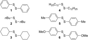
Structures of the symmetrical disulfides 1–6 utilized in this investigation.
From these six symmetrical disulfides several mixed unsymmetrical disulfides (7–21) might be generated when the metathesis of the sulfide residues does not follow steric or electronic restrictions but proceed statistically (Figure 2). In the first step, we investigated transformations under which two symmetrical disulfides (1 and 2) can be converted to a (statistical) mixture of the possible disulfides including the new and desired mixed disulfide 7.
Figure 2.

Structures of the desired unsymmetrical disulfides 7–21 in this investigation.
Two‐disulfide matrix
When the electrolysis of 1 and 2 was performed in an undivided cell, the yield of mixed disulfide 7 was 50 % (determined by GC‐FID analysis) and could be isolated in 42 % yield (corrected yield due to some contamination with 2) by column chromatography.
In the next step, the electrolysis of the two disulfides 1 and 2 were performed in a divided cell and the formation of the desired mixed unsymmetrical disulfide 7 was observed (identified by GCMS analysis; Figure 3) in both cell compartments (Scheme 3). Furthermore, the rate for the formation and the yield of 7 were nearly identical in both compartments (see Supporting Information chapter 2.3, Tables S6 and S7). It must be mentioned that extended electrolysis led to side‐products in the anodic compartment and oxidation of the disulfide to oxo‐species which could be observed by GCMS analysis. In the cathodic compartment the complete consumption of the disulfides was observed associated with the formation of a black precipitate at the platinum cathode in this divided cell design.
Figure 3.

GCMS analysis of the electrolysis with the two disulfides 1 and 2 by anodic oxidation. ISTD=n‐dodecane as internal standard. The numbers in parenthesis express the [M]+ ion masses.
Scheme 3.
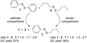
Results of constant current electrolysis in a divided cell. Conditions: divided cell; Pt/ Pt (1.0 cm2 each); 10 mA; 1/2 (0.5 mmol each), CH3CN (10 mL), TBABF4 (0.3 m), rt.
These electrochemical sulfur–sulfur bond metathesis reactions were tested in acetonitrile, dimethylformamide and methanol as solvent and the best results were obtained in acetonitrile (see Supporting Information chapter 2.7, Table S12). Also, among several supporting electrolytes, tetrabutylammonium tetrafluoroborate (TBABF4) proved to be most efficient. The formation of the product 7 in the anode compartment as well as in the cathode compartment was determined in an averaged statistical ratio of 1:2:7=1.0:1.0:2.7 from the GC‐FID trace. Therefore, we assume that in this setup one or two electron transfer processes to or from the disulfides occur that led to the formation of the product 7 by associative/dissociative processes (probably via the species R3S3 + or RS.) as mentioned above. The observed difference to the theoretical ratio in disulfide distribution of 1:1:2 can be a result of generating ionic species, which are removed during sample preparation for GC‐FID analysis. Furthermore, it is also possible that there is a slight thermodynamic preference towards the unsymmetrical disulfide 7, which can explain this deviation.
The formation of 7 could be further improved when one of the disulfide components (e.g. compound 2) was applied in excess. The GC ratio increased to 89 % of 7 (with respect to the minor component 1) in the presence of 3.0 equiv of 2 and reached 98 % when 5.0 equiv of 2 were used (see Supporting Information chapter 2.9, Table S14).
As these results show, the stoichiometric reduction/oxidation of the disulfides is probably not needed and is even counter‐productive. This aspect was confirmed when a „catalytic“ amount of electricity was applied. After passing 0.1 F mol−1 (5 mol % of the theoretical amount of electricity for the reduction and oxidation) through the electrochemical cell, the statistical mixture of 1:1:2 was already established after only 8 min reaction time. Although these results were already encouraging, we also investigated an alternating current approach in (un)divided cells at ambient temperature to form product 7. For this purpose the polarisation of the electrolysis was held at a constant current (e.g. 10 mA) for a specified period of time (t 1; pulse time), followed by a quiet time (t 2) and then the polarisation of the electrodes was altered for another fixed time interval (t 1); and the total time of the electrolysis is represented by t 3.
The effect (for the solution near the electrode) is an oxidation pulse, then a quiet time followed by a reduction pulse. The current profile for one electrode—as this methodology makes no difference which electrode serves as anode or cathode—is shown in Figure 4.16 The rationale for applying this type of pulse electrolysis was the idea that the reduction of the disulfides 1 and 2 proceeds at the electrode when a reduction pulse is applied and the change of polarisation would oxidise the thiolates back to the disulfides. The quiet time t 2 was introduced to allow diffusion of the electrogenerated active species into the solution before the reversed pulse would quench these species.
Figure 4.
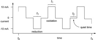
Schematic alternating current profile for one electrode over time.
In addition, the diffusion of the electrogenerated species from one electrode to the other electrode over a relatively large distance would not be needed. More importantly, if the reductively electrogenerated species would be absorbed on the cathode surface diffusion to the anode would be impossible, but the application of an oxidation pulse would recombine the reduced sulfide species to form sulfur–sulfur bonds again and eventually this should lead to the formation of the mixed disulfide 7. Therefore, we expected a statistical mixture of the disulfides 1, 2 and 7 to be formed over time when applying alternating current.
This setup led to the formation of the desired mixed unsymmetrical disulfide 7 again in a short period of time whereas the formation of the black precipitate could be avoided, no side products were encountered and the disulfides were not consumed or decomposed as was the case under constant current electrolysis (see Supporting Information appendix, Figure S13). Even the application of 10.0 F mol−1 in this alternating current setup led to the statistical ratio and the peaks in GCMS in reference to the internal standard remained constant. This type of reaction was tested in a divided cell utilising two different electrode materials and all other components were held identical. Accordingly, the effect of the electrode material upon the formation of the mixed disulfides could be investigated. The best results were observed when the reactions were performed at a platinum electrode or glassy carbon electrode whereas inferior results were obtained when copper, stainless steel and carbon fiber electrodes were used (see Supporting Information chapter 2.7, Table S11).17 Based on these positive effects all other disulfide metathesis reactions were conducted with the alternating current electrolysis setup.
In addition, the equilibration of the disulfide distribution was investigated by comparison of the alternating current approach in reference to a thiolate mediated metathesis. Therefore, a catalytical amount of sodium thiophenolate (25 mol %) was used to achieve the metathesis (see Supporting Information chapter 2.4). In contrast to the alternating current approach, the thiolate mediated metathesis proved to be a slow process and even after 1520 min reaction time only 15 % yield of the mixed disulfide 7 was obtained (for the comparison see Supporting Information chapter 2.4, Figure S4).
Next, the pulse times t 1 were altered in a range from 40 seconds to 4 milliseconds to determine the formation of 7 even under fast alternating current conditions (see Supporting Information chapter 2.8, Table S13). Even at these short pulse times (t 1=4 ms; t 2=1 ms) the formation of the mixed product 7 could be observed, but prolonged electrolysis time was needed. Furthermore, the formation of product 7 only occurred at the platinum electrode while at the glassy carbon electrode the product formation was less than 10 %. These observations indicated that the charging of the electrodes in terms of a capacitor is on the one hand a relatively fast process on platinum; on the other hand, it cannot be neglected in terms of unproductive current consumption when short pulse times t 1 are applied. For relatively long pulse times (e.g. t 1>1 s) the capacitor energy consumption can be neglected. In summary, these results showed that the formation of reactive species is a fast process and that these reactive species are unlikely to be adsorbed on the electrode surface but diffuse into solution to initiate the metathesis of the sulfur–sulfur bond of disulfide molecules. In a control experiment in the absence of electricity no mixed disulfide was observed, but this aspect became of interest when matrices with a higher number of disulfides were applied (see below).
Three‐ and six‐disulfide matrix
With these conditions in hand, the next step in this investigation, utilising three disulfides in one setup, was undertaken in order to illustrate that a more complex mixture of symmetrical and unsymmetrical disulfides could be formed and analysed. Therefore, a small library of disulfide compounds was envisaged. When a matrix consisting out of three different aromatic and aliphatic disulfides (1, 2 and 4) were electrolyzed under the alternating current conditions (t 1=4 s; t 2=1 s; I=10 mA, t 3=80 min, 0.8 F mol−1) three additional mixed disulfides should be formed (Scheme 4).
Scheme 4.

Sulfur–sulfur bond metathesis matrix consisting of three symmetrical disulfides leading to six disulfides.
The GCMS analysis of the reaction mixture shown in Figure 5 illustrates the formation of all possible products, identified by their molecular masses and fragmentation patterns. In this case a baseline separation of the individual species could be realised (see Supporting Information chapter 2.11.1).
Figure 5.
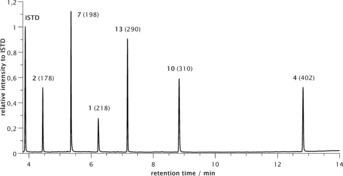
GCMS analysis (total ion spectrum mode) of the electrolysis of the matrix with three disulfides 1, 2 and 4.
It should be noted that the peak height and the integral of the peaks do not directly correlate with the mass balance. Though, a static mixture of all six compounds was obtained, although no detailed quantification of the GCMS spectra was undertaken. Nevertheless, with increasing numbers of matrix members, the possible combinations increase significantly, and problems might arise.
Eventually, a matrix consisting out of six different disulfides were applied in an alternating current approach (Scheme 5, see also Supporting Information chapter 2.11.2) and up to 21 possible disulfides could be formed (t 1=4 s; t 2=1 s; I=10 mA, t 3=160 min, 1.6 F mol−1). In this case, we selected the symmetrical disulfides with respect to their molecular masses and this aspect proved to be very useful for the analysis of the reaction mixture. The GCMS analysis seemed to reach its limits as not all peaks could be separated on a regular GCMS column (Macherey–Nagel Optima 5 HT). This can best be seen at the peak at 6.25 min of the chromatogram (Figure 6) which consists of three different disulfides overlapping in one broad peak (Figure 7, left). But the chosen starting materials have different molecular masses so that each combination of symmetrical or unsymmetrical disulfides resulted in product disulfides with different molecular masses. Accordingly, when the GCMS analysis was switched from total ion current measurement to selected ion monitoring, the three different components could be differentiated and the peaks resolved (Figure 7, right).
Scheme 5.

Sulfur–sulfur bond metathesis matrix consisting of six symmetrical disulfides.
Figure 6.
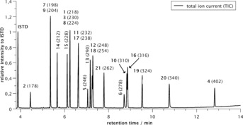
GCMS analysis of the electrolysis of the matrix with six disulfides (total ion spectrum mode).
Figure 7.

Exemplary comparison of a total ion spectrum (left) versus a selected ion monitoring mode GCMS analysis (right) for the chromatogram from 6.15–6.30 min for the GCMS peak consisting of compounds 1, 3 and 8.
Also in this case, we tested the stability of the disulfide mixture in the electrolyte for 1 hour without applying electricity (see Supporting Information chapter 2.10). Interestingly, in the case of the matrix consisting of six disulfides (1–6) we observed mixed unsymmetrical disulfides; but remarkably only from the aromatic disulfides in significant amounts (Scheme 6).
Scheme 6.
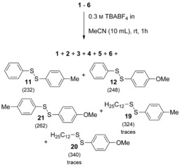
Control experiment of the sulfur–sulfur bond metathesis matrix consisting of six symmetrical disulfides in the absence of electricity.
In addition, traces of unsymmetrical disulfides 19 and 20, resulting from metathesis reaction of 4 and 6, were observed. The remaining aliphatic disulfides did not undergo the metathesis reaction in the absence of electricity (Figure 8). Also, addition of NaSPh as a possible initiator for the sulfur–sulfur bond metathesis did not result in the formation of any other mixed disulfides.
Figure 8.

GCMS analysis (total ion spectrum mode) of the control experiment above in absence of electricity with borosilicate glass ware.
Further investigations on the aromatic disulfide metathesis were carried out with a two‐disulfide matrix consisting of 1 and 5 (see Supporting Information chapter 2.10.3). When this matrix was stirred under inert atmosphere, the mixed disulfide 11 was also formed. However, stirring in the dark let to the suppression in disulfide formation. Also, when the matrix was stirred in a plastic container (PTFE vessel) instead in a glass flask (borosilicate or soda‐lime glass) the formation of the aromatic mixed disulfides could be suppressed to a large extent.18 Furthermore, the addition of crushed glass into the PTFE reaction vessel did not initiated the sulfur–sulfur bond metathesis reaction of the aromatic disulfides to form the product 11 to a similar extent as in the glass flask. We suggest that the formation of the unsymmetrical disulfide 11 benefits from the higher alkali and alkaline earth metal ion content in soda‐lime glass in contrast to borosilicate glass in combination with visible light. Further studies are going on to prove this hypothesis.
Mixing and expanding matrices
The dynamic nature of this type of disulfide chemistry was next investigated when the six‐membered disulfide matrix was split into two matrices consisting of three disulfides each (Scheme 7, see also Supporting Information chapter 2.11.2.1.2). These two matrices were electrolysed under alternating current conditions (t 1=4 s; t 2=1 s; I=10 mA, t 3=15 min, 0.15 F mol−1) and the individual mixtures were analysed by GCMS (see Figures 5 and Figure 9). As before, each possible combination of disulfides was detectable by GCMS analysis (by selected ion monitoring).
Scheme 7.
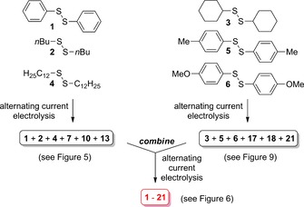
Split and combine of matrices to establish the dynamic nature of the formation of disulfides under alternating current conditions (t 1=4 s; t 2=1 s; I=10 mA, t 3=15 min, 0.15 F mol−1).
Figure 9.

GCMS analysis of the sulfur–sulfur bond metathesis matrix consisting of disulfides 3, 5 and 6.
However, when the two solutions were mixed directly after electrolysis (<1 min) no further electrolysis was needed to form the identical result obtained from the electrolysis of the original undivided six disulfide matrix whose GCMS analysis is identical to this shown in Figure 6. We reasoned that active species for the disulfide metathesis were still present in solution and initiated the metathesis reactions. Control experiments revealed that the filtration through a small plug of silica gel removed the active species and after mixing of the two matrix solutions no further metathesis reaction was observed.
Only when a further catalytic amount of electricity (7.5 mol %) was applied (t 1=4 s; t 2=1 s; I=10 mA, t 3=15 min, 0.15 F mol−1), the complete number of product possibilities of the matrix (1–21) was formed.
Inspired by the initial observation that the active species for the metathesis reaction are still present in the reaction mixture, we decided to investigate an expanding‐type approach to realise a dynamic library (see Supporting Information chapter 2.11.2.1.1). Accordingly, when the two disulfide matrix containing disulfide 1 and 2 was electrolyzed under the standard conditions (t 1=4 s; t 2=1 s; I=10 mA, t 3=15 min, 0.15 F mol−1) utilising a catalytic amount of current (7.5 mol %) and the electrolysis was stopped the matrix could be expanded by addition of another disulfide 4 towards a three disulfide matrix. After another electrolysis cycle of 15 min utilising the above‐mentioned condition the expected number of disulfides could be identified by GCMS analysis. Thereafter, the addition of the fourth disulfide 3 was undertaken and this procedure was extended until all six components 1–6 were present. At the end the undivided six‐membered matrix was obtained in the same manner (see Figure 6).
Conclusions
In this investigation we were able to show that the sulfur–sulfur bond metathesis can be realised by catalytic amounts of electricity and we applied an alternating current approach to ensure the formation of all combinations of symmetrical und unsymmetrical disulfides. Furthermore, alternating current avoided the formation of undesired side products, the consumption of the starting materials in unproductive reaction pathways and the formation of insulating precipitates on the electrode surface in contrast to direct current. In addition, alternating current electrolysis allows the formation of the desired disulfides whether in catalytic or over‐stoichiometric amounts of current without decomposition. The analysis of the products was realised by GCMS and GC‐FID analysis and the choice of starting materials with differing molecular masses helped to analyse overlapping peaks when selected ion monitoring was utilised in the GCMS analysis. Therefore, all disulfides 1–21 could be identified by GCMS and in one example, the presence of three disulfides in a broad peak could be proven. The dynamic nature of the matrices could be shown by split and mix approaches. When the mixing of the matrices were performed shortly after electrolysis the presence of active species in the solution allowed the further formation of the complete matrix without any further electrolysis needed. However, when the active species were removed by filtration, renewed electrolysis started the process of the sulfur–sulfur metathesis right away. Therefore, we are convinced that these results represent a much‐needed tool which will be of great interest for those scientists conducting systems chemistry in the future where fast responses to changing conditions rely on reversible processes that can be easily initiated. The sulfur–sulfur bond metathesis seems to be an excellent example for this type of chemistry and the alternating current electrolysis is a key element to achieve this goal.
Experimental Section
General Procedure for an alternating current electrolysis: Both compartments of an H‐type divided cell were equipped with a magnetic stirring bar and charged with 988 mg (3.00 mmol) TBABF4. The supporting electrolyte was dissolved in 10 mL CH3CN in each compartment. Afterwards, 109 mg (0.500 mmol, 1.0 equiv) diphenyl disulfide (1), 95.1 μL (0.500 mmol, 1.0 equiv) di‐n‐butyl disulfide (2), 115 mg (0.500 mmol, 1.0 equiv) dicyclohexyl disulfide (3), 201 mg (0.499 mmol, 1.0 equiv) di‐n‐dodecyl disulfide (4), 123 mg (0.500 mmol, 1.0 equiv) di‐p‐tolyl disulfide (5), 143 mg (0.500 mmol, 1.0 equiv) Bis(p‐methoxyphenyl) disulfide (6) and 0.5 mL (0.500 mmol, 1.0 equiv) n‐dodecane solution (1.0 m in CHCl3) as internal standard were added in both compartments. At last, the electrodes (first compartment platinum, second compartment glassy carbon) were immerged into the solution (surface area: 1.0 cm2) and a constant current (10 mA) with an alternation in electrode polarisation of 5 s (t 1=4 s pulse time, t 2=1 s quiet time) was applied. After 15 min (0.15 F mol−1) a sample for GCMS analysis was taken. The determination of the ratio in disulfide distribution was accomplished by GC‐FID or GCMS analysis. Furthermore, for the resolution of overlaid components in the gas chromatogram measurements in selected ion monitoring (SIM) mode were performed.
Conflict of interest
The authors declare no conflict of interest.
Supporting information
As a service to our authors and readers, this journal provides supporting information supplied by the authors. Such materials are peer reviewed and may be re‐organized for online delivery, but are not copy‐edited or typeset. Technical support issues arising from supporting information (other than missing files) should be addressed to the authors.
Supplementary
L. E. Sattler, C. J. Otten, G. Hilt, Chem. Eur. J. 2020, 26, 3129.
In memory of Jun‐ichi Yoshida
References
- 1.
- 1a. Ludlow R. F., Otto S., Chem. Soc. Rev. 2008, 37, 101; [DOI] [PubMed] [Google Scholar]
- 1b. von Kiedrowski G., Otto S., Herdewijn P., J. Syst. Chem. 2010, 1, 1; [Google Scholar]
- 1c. Ashkenasy G., Hermans T. H., Otto S., Taylor A. F., Chem. Soc. Rev. 2017, 46, 2543. [DOI] [PubMed] [Google Scholar]
- 2.
- 2a. Bartolec B., Leonetti G., Li J., Smit W., Altay M., Santiago G. M., Yan Y., Otto S., Langmuir 2019, 35, 5787; [DOI] [PMC free article] [PubMed] [Google Scholar]
- 2b. Liu B., Pappas C. G., Zangrando E., Demitri N., Chmielewski P. J., Otto S., J. Am. Chem. Soc. 2019, 141, 1685; [DOI] [PMC free article] [PubMed] [Google Scholar]
- 2c. Malakoutikhah M., Schaeffer G., Santiago G. M., Yang S., Marić I., Otto S., J. Syst. Chem. 2019, 7, 9. [Google Scholar]
- 3. Rowan S. J., Cantrill S. J., Cousins G. R. L., Sanders J. K. M., Stoddart J. F., Angew. Chem. Int. Ed. 2002, 41, 898; [DOI] [PubMed] [Google Scholar]; Angew. Chem. 2002, 114, 938. [Google Scholar]
- 4.
- 4a. Reek J. N. H., Dydio P. F., Eur. Pat. Appl. EP 2559484, 2013;
- 4b. Patroniak V., Wiadomosci Chemiczne 2010, 64, 285; [Google Scholar]
- 4c. Agrawal U. C., Nigam H. L., J. Indian Chem. Soc. 2008, 85, 677. [Google Scholar]
- 5.For the electrochemistry of thioles and disulfides, see:
- 5a. Torii S., Electroorganic Reduction Synthesis, Vol. 1, 2006, Wiley-VCH, Weinheim, Chapter 6; see also: [Google Scholar]
- 5b. Yan M., Kawamata Y., Baran P. S., Chem. Rev. 2017, 117, 13230; [DOI] [PMC free article] [PubMed] [Google Scholar]
- 5c. Kärkäs M. D., Chem. Soc. Rev. 2018, 47, 5786; [DOI] [PubMed] [Google Scholar]
- 5d. Wiebe A., Gieshoff T., Möhle S., Rodrigo E., Zirbes M., Waldvogel S. R., Angew. Chem. Int. Ed. 2018, 57, 5594; [DOI] [PMC free article] [PubMed] [Google Scholar]; Angew. Chem. 2018, 130, 5694; [Google Scholar]
- 5e. Echeverria P.-G., Delbrayelle D., Letort A., Nomertin F., Perez M., Petit L., Aldrichimica Acta 2018, 51, 3; [Google Scholar]
- 5f. Kitada S., Takahashi M., Yamaguchi Y., Okada Y., Chiba K., Org. Lett. 2012, 14, 5960–5963; [DOI] [PubMed] [Google Scholar]
- 5g. Matsumoto K., Shimazaki H., Sanada T., Shimada K., Hagiwara S., Suga S., Kashimura S., Yoshida J.-i., Chem. Lett. 2013, 42, 843–845; [Google Scholar]
- 5h. Wang P., Tang S., Huang P., Lei A., Angew. Chem. Int. Ed. 2017, 56, 3009–3013; [DOI] [PubMed] [Google Scholar]; Angew. Chem. 2017, 129, 3055–3059. [Google Scholar]
- 6.For recent examples, see:
- 6a. Matysiak B. M., Nowak P., Cvtila I., Pappas C. G., Liu B., Komáromy D., Otto S., J. Am. Chem. Soc. 2017, 139, 6744; [DOI] [PMC free article] [PubMed] [Google Scholar]
- 6b. Bartolec B., Altay M., Otto S., Chem. Commun. 2018, 54, 13096; [DOI] [PubMed] [Google Scholar]
- 6c. Altay M., Altay Y., Otto S., Angew. Chem. Int. Ed. 2018, 57, 10564; [DOI] [PubMed] [Google Scholar]; Angew. Chem. 2018, 130, 10724; [Google Scholar]
- 6d. Otto S., Furlan R. L. E., Sanders J. K. M., Science 2002, 297, 590–593. [DOI] [PubMed] [Google Scholar]
- 7.
- 7a. Verschueren R. H., De Borggraeve W. M., Molecules 2019, 24, 2122; [Google Scholar]
- 7b. Sperry J. B., Wright D. L., Chem. Soc. Rev. 2006, 35, 605; [DOI] [PubMed] [Google Scholar]
- 7c. Lund H. A., J. Electrochem. Soc. 2002, 149, S21. [Google Scholar]
- 8. Hammerich O., Speiser B., Organic Electrochemistry, 5th ed., 2016, Taylor&Francis, Boca Raton. [Google Scholar]
- 9.
- 9a. Do Q. T., Elothmani D., Le Guillanton G., Simonet J., Tetrahedron Lett. 1997, 38, 3383; for recent reviews on electrochemical cation-pool chemistry, see: [Google Scholar]
- 9b. Yoshida J.-i., Shimizu A., Hayashi R., Chem. Rev. 2018, 118, 4702; [DOI] [PubMed] [Google Scholar]
- 9c. Matsumoto K., Suga S., Yoshida J.-i., Org. Biomol. Chem. 2011, 9, 2586. [DOI] [PubMed] [Google Scholar]
- 10. Huang P., Wang P., Tang S., Fu Z., Lei A., Angew. Chem. Int. Ed. 2018, 57, 8115; [DOI] [PubMed] [Google Scholar]; Angew. Chem. 2018, 130, 8247. [Google Scholar]
- 11.
- 11a. Boryczka S., Elothmani D., Do Q. T., Simonet J., Le Guillanton G., J. Electrochem. Soc. 1996, 143, 4027; [Google Scholar]
- 11b. Do Q. T., Elothmani D., Le Guillanton G., Electrochim. Acta 2005, 50, 4792. [Google Scholar]
- 12.
- 12a. Grogger C., Fattakhov S. G., Jouikov V. V., Shulaeva M. M., Reznik V. S., Russ. J. Gen. Chem. 2005, 75, 386; [Google Scholar]
- 12b. Antonello S., Benassi R., Gavioli G., Taddei F., Maran F., J. Am. Chem. Soc. 2002, 124, 7529. [DOI] [PubMed] [Google Scholar]
- 13.For some selected examples, see:
- 13a. Matsumoto K., Fujie S., Suga S., Nokami T., Yoshida J.-i., Chem. Commun. 2009, 5448. [DOI] [PubMed] [Google Scholar]
- 14. Antonello S., Maran F., Chem. Soc. Rev. 2005, 34, 418. [DOI] [PubMed] [Google Scholar]
- 15. Borsari M., Cannio M., Gavioli G., Electroanalysis 2003, 15, 1192. [Google Scholar]
- 16.Alternating current has rarely been used in organic synthesis. For some examples, see:
- 16a. Lee B., Naito H., Nagao M., Hibino T., Angew. Chem. Int. Ed. 2012, 51, 6961; [DOI] [PubMed] [Google Scholar]; Angew. Chem. 2012, 124, 7067; [Google Scholar]
- 16b. Lee S. M., Roseman J. M., Zartman C. B., Morrison E. P., Harrison S. J., Stankiewicz C. A., Middleton W. J., J. Fluorine Chem. 1996, 77, 65; [Google Scholar]
- 16c. Savett S. C., Lee S. M., Bradley A. Z., Kneizys S. P., LoBue J. M., Middleton M. J., Microchem. J. 1993, 48, 192; [Google Scholar]
- 16d. Kraj A., Brouwer H.-J., Reinhoud N., Chervet J.-P., Anal. Bioanal. Chem. 2013, 405, 9311–9320. [DOI] [PMC free article] [PubMed] [Google Scholar]
- 17.The carbon fiber electrodes were manufactured from material, which was purchased from R&G Faserverbundwerkstoffe GmbH, Germany (item description: Carbon roving PyrofilTM TR50S 6k/400 tex); for a recent application, see: Röse P., Emge S., König C. A., Hilt G., Adv. Synth. Catal. 2017, 359, 1359. [Google Scholar]
- 18.For the analysis of the reaction mixture, a sample was taken from the reaction vessel by a PTFE pipette and put in a PTFE vial for GCMS analysis.
Associated Data
This section collects any data citations, data availability statements, or supplementary materials included in this article.
Supplementary Materials
As a service to our authors and readers, this journal provides supporting information supplied by the authors. Such materials are peer reviewed and may be re‐organized for online delivery, but are not copy‐edited or typeset. Technical support issues arising from supporting information (other than missing files) should be addressed to the authors.
Supplementary


