

Abstract
Adverse clinical outcomes for total disc arthroplasty (TDA), including subsidence, heterotopic ossification, and adjacent‐level vertebral fracture, suggest problems with the underlying biomechanics. To gain insight, we investigated the role of size and stiffness of TDA implants on load‐transfer within a vertebral body. Uniquely, we accounted for the realistic multi‐scale geometric features of the trabecular micro‐architecture and cortical shell. Using voxel‐based finite element analysis derived from a micro‐computed tomography scan of one human L1 vertebral body (74‐μm‐sized elements), a series of generic elliptically shaped implants were analyzed. We parametrically modeled three implant sizes (small, medium [a typical clinical size], and large) and three implant materials (metallic, E = 100 GPa; polymeric, E = 1 GPa; and tissue‐engineered, E = 0.01 GPa). Analyses were run for two load cases: 800 N in uniform compression and flexion‐induced anterior impingement. Results were compared to those of an intact model without an implant and loaded instead via a disc‐like material. We found that TDA implantation increased stress in the bone tissue by over 50% in large portions of the vertebra. These changes depended more on implant size than material, and there was an interaction between implant size and loading condition. For the small implant, flexion increased the 98th‐percentile of stress by 32 ± 24% relative to compression, but the overall stress distribution and trabecular‐cortical load‐sharing were relatively insensitive to loading mode. In contrast, for the medium and large implants, flexion increased the 98th‐percentile of stress by 42 ± 9% and 87 ± 29%, respectively, and substantially re‐distributed stress within the vertebra; in particular overloading the anterior trabecular centrum and cortex. We conclude that TDA implants can substantially alter stress deep within the lumbar vertebra, depending primarily on implant size. For implants of typical clinical size, bending‐induced impingement can substantially increase stress in local regions and may therefore be one factor driving subsidence in vivo.
Keywords: biomechanics, finite element analysis, impingement, subsidence, total disc arthroplasty, total disc replacement
Little is known about the stresses and load‐transfer behavior within a vertebral body supporting a lumbar total disc arthroplasty implant. Using data from a micro‐computed tomography scan, generically shaped total disc arthroplasty implants were virtually implanted on a human lumbar vertebral body and analyzed using parametric micro‐computed tomography‐based finite element analysis in compression and flexion‐induced impingement.

1. INTRODUCTION
Almost 500 000 spinal fusions are performed annually in the United States to treat degenerative disc disease and other spinal pathologies.1 While mostly successful,2 evidence suggesting that reduced segmental mobility may accelerate degenerative changes at adjacent levels3, 4, 5 has driven interest in motion‐preserving approaches, such as total disc arthroplasty (TDA).6 This class of implants can allow for some degree of flexion/extension, lateral bending, and axial rotation between adjacent vertebrae.7, 8, 9 The underlying premise is that this mobility produces a more natural kinematic and biomechanical environment in the adjacent vertebrae—that is, motion and load‐transfer patterns that are closer to those occurring without an implant.
Clinical outcomes following TDA are mixed. Problems including heterotopic ossification,10, 11, 12 adjacent‐level vertebral fracture,13, 14, 15 and implant subsidence16, 17, 18 suggest problems with the resulting biomechanics. Reduced implant coverage—a smaller footprint of the implant on the vertebral endplate—is associated with elevated interfacial stresses19 and a higher incidence of implant subsidence,16 suggesting that small implants may cause high stresses and failure of underlying bone. Implants that cover an equivalent percentage of the vertebral endplate but have different shapes can require different forces to subside into the bone because they recruit different regions of the endplate and underlying trabecular microstructure.20 Despite those insights, the fundamental load‐transfer behavior within a vertebral body supporting a TDA implant remains largely unknown. For example, it is not known whether implant‐induced changes in stress occur in local regions adjacent to the implant and then dissipate in deeper regions, or whether the extent of the vertebral body is impacted. Similarly, it is not known how stresses within the trabecular microstructure change as a function of implant size or material. The etiology of subsidence also remains unclear. Data from Punt et al16 show that for 60% (21/35) of clinically diagnosed cases of subsidence, the implant footprint did not subside in a parallel manner but rather rotated by at least 5° relative to the bony endplate. This suggests to us that bending could be involved in subsidence, though this link has not been previously established.
In part, these uncertainties arise because of the structural complexity of the human vertebral body, including the spatially variable trabecular microarchitecture and thin cortical shell and endplate. Addressing this issue, our goal was to elucidate the role of implant size and stiffness on load‐transfer behavior within the vertebral body following TDA, accounting for realistic multi‐scale geometric features of human vertebral bone. To capture these features, we employed micro‐computed tomography (μCT)‐based finite element analysis. The high resolution and mechanistic nature of μCT‐based finite element analysis has provided unique insight into the mechanisms of osteoporotic wedge‐fracture,21 the mechanical role of the trabecular micro‐structure,22 in vivo structural changes to bone,23 and fundamental properties of bone tissue24, 25 and is therefore well suited to investigate tissue‐level mechanics following TDA. Specifically, for both uniform compression and flexion‐induced anterior impingement, we investigated the effects of implant size and stiffness on trabecular‐cortical load‐sharing behavior, stress and stress changes in the vertebral bone tissue, and the spatial distribution of tissue at the highest risk of failure. The resulting insight can help elucidate fundamental biomechanical behavior for this class of device, including how implant design may facilitate the replication of a natural biomechanical environment in adjacent vertebrae.
2. MATERIALS AND METHODS
2.1. Study design
Our study comprised parametric, high‐resolution, μCT‐based finite element analysis of a human vertebral body virtually implanted with generically shaped elliptical TDA implants of varying sizes and stiffness and loaded in compression and flexion‐induced anterior impingement. We assumed that subtle details of the implant geometry have only a secondary effect on tissue‐level stresses within the vertebral body (Appendix A). Thus, to simplify the modeling effort, generic implants were modeled that comprised 3‐mm‐thick elliptical cylinders with varying major and minor diameters. Implant models were compared against an intact (no‐implant) case, which simulated loading via a disc‐like material covering the superior and inferior endplates.
2.2. Specimen preparation and μCT scanning
We analyzed μCT data from a separate study of one human L1 vertebral body from a de‐identified 80‐year‐old male cadaver with no history of metabolic bone disorder. The bone volume fraction (BV/TV) was 0.23 for the entire vertebral body (cortical shell included). This value is higher than has been reported for osteoporotic vertebrae26 and is therefore typical of what would be expected for a TDA candidate. The μCT scan had an isotropic pixel size of 37 μm and the posterior elements were removed to isolate the vertebral body. To reduce computational cost, the scan was coarsened to 74 μm before the hard‐tissue and marrow were segmented using a global threshold value. Bone tissue was then compartmentalized into trabecular, cortical and endplate tissue using custom algorithms described elsewhere (Figure 1A).27 A planar surface was virtually created superiorly to mimic surgical preparation28, 29 prior to TDA implantation. This required resection through parts, but not all, of the osseous endplate.
Figure 1.

Mid‐sagittal cross‐section (0.5 mm thick) showing (A) the differentiation of trabecular (light gray), cortical (blue), and endplate (red) tissue. Boundary conditions and displaced shapes are shown for the (A) intact disc in compression, (B) intact disc in flexion, (C) implant in compression, and (D) implant in flexion. The implant components depicted above the footplate in (D) were not explicitly modeled but are shown to illustrate impingement which motivates our flexion boundary conditions
2.3. Finite element analysis
Each 74 μm voxel in the coarsened scan was converted into an eight‐noded hexahedral finite element.27 A TDA implant, also modeled using voxels, was placed such that the implant center coincided with anterior‐posterior (A/P) and medial‐lateral (M/L) midpoint of the vertebral body (the A/P dimension was measured from the vertebral foramen).
To simulate compressive loading of an intact disc, a uniform compressive displacement boundary condition was applied to the superior disc (Figure 1A). Following calculation of the finite element solution, results were scaled linearly to produce a net reaction force of 800 N (approximately 1× body weight30), a typical force at that spinal level for static standing.31 To simulate flexion of an intact disc, a displacement boundary condition was used to rotate the disc in the mid‐sagittal plane about the far posterior‐superior point, simulating flexion over a single motion segment (Figure 1B).21, 32 Results were then scaled linearly to produce an overall reaction force of 800 N. While flexion can increase loads on the spine 2‐ to 3‐fold compared to what was modeled here,31, 33 a reaction force of 800 N was maintained in order to facilitate comparison across models. Compression of an implanted segment was modeled by applying a uniform force of 800 N to the superior implant footplate (Figure 1C). Flexion of an implanted segment was modeled by assuming impingement between the footplate and the insert (Figure 1D). There is substantial evidence that impingement occurs in vivo in flexion/extension and lateral bending for both unconstrained (eg, Charité) and semi‐constrained (eg, ProDisc‐L, activL) devices.34, 35, 36, 37, 38, 39, 40, 41 Analysis of retrieved implants and in vitro experiments suggests that large loads are transmitted through the impinged regions during bending.35, 37, 40 Therefore, flexion of an implanted segment was modeled by applying a net force of 800 N to a 2 mm thick, 90° arc of the footplate, representing load‐transfer through the footplate induced by impingement (Figure 2). The distance from the implant center to the impinged region (r) was set as 40% of the footplate A/P diameter and was chosen because it represents a typical impingement moment arm for devices used clinically. For all models, an intervertebral disc‐like material was modeled inferiorly using a roller‐type (symmetry) boundary condition applied to the base of a 4‐mm‐thick disc, thereby simulating an 8‐mm‐thick disc with unconstrained bulging.
Figure 2.

Flexion of an implanted segment was modeled by applying a force through an arc (yellow) to simulate impingement. θ = 90°, t = 2 mm, r = 40% of the footplate anterior‐posterior diameter
All bone elements were assigned the same elastic material properties (E = 10.3 GPa, ν = 0.3042). While absolute values of stress in the bone directly depend on the choice of tissue material properties, the relative outcomes are insensitive to uncertainties in tissue modulus over a realistic physiologic range (Appendix B). Disc elements were assigned material properties consistent with the measured effective (homogenized) modulus of the disc at a low loading rate (E = 8 MPa, ν = 0.4543). Implant modulus was parametrically varied as described below (ν = 0.33). Perfect bonding was assumed at all interfaces, thereby modeling full footplate fixation in the bone.44, 45
As described below, a total of 20 analyses were run. Depending on implant size, individual models had 36 to 46 million elements and 141 to 174 million degrees of freedom. All analyses were linearly elastic and were solved on a supercomputing cluster (Stampede2, Austin, Texas) using a custom finite element code that included a parallel mesh partitioner and an algebraic multi‐grid solver.46 A typical analysis utilized 1100 processors, 3000 GB of memory, and required over 200 CPU hours.
2.4. Parametric variation
We parametrically varied both implant size and elastic modulus. Three implant sizes were modeled to represent small, medium, and large implants. The major and minor implant diameters were defined as 50%, 75% and 100% of the M/L and A/P dimensions of the vertebral body (44.6 mm M/L, 31.5 mm A/P) for the cases of small, medium, and large implants, respectively. A survey of lumbar TDA implants (Charité, DePuy‐Synthes, Maverick, Medtronic, ProDisc‐L, DePuy‐Synthes, MobidiscL, Zimmer‐Biomet, activL, Aesculap) showed dimensional ranges of 28.5‐42.5 and 23.0‐36.0 mm (M/L and A/P, respectively, min‐max). Thus, our medium implant is within the range of clinically used implants, while the small and large implants represent dimensional extremes. For each implant size, three implant materials were analyzed. Elastic moduli of 100 GPa, 1 GPa, and 0.01 GPa were chosen to represent generic metallic, polymeric, and hypothetical tissue‐engineered implants, respectively.43, 47
2.5. Outcomes
The primary outcomes were: (a) trabecular‐cortical load‐sharing behavior; (b) the spatial distribution of tissue at the highest risk of initial failure; and (c) stress and stress changes relative to the intact model in the bone tissue. Trabecular‐cortical load‐sharing was quantified using the cortical load fraction, which was calculated at each transverse slice as the ratio of axial force in the cortical bone to that in the whole vertebra; trabecular load fraction equals unity minus cortical load fraction.27 High‐risk tissue was defined as the 10% of bone tissue at the highest risk of initial failure.21 This was quantified by taking the ratio of the maximum and minimum principal stresses of each bone element (calculated at the element centroids) to its tensile (61 MPa) or compressive (150 MPa) yield stress,48 respectively, then taking the higher value of this ratio. After ranking values across all elements, high‐risk tissue was defined as the top 10% of values.21, 43 To evaluate tissue‐level stress in the bone, the minimum principal stress (calculated at the element centroids) was visually plotted and compared. To quantify changes in stress compared to normal physiologic loading, the von Mises stress (calculated at the element centroids) for each implanted model was subtracted, element‐by‐element, from the intact model.
3. RESULTS
In both axial compression and flexion‐induced anterior impingement, the presence of an implant altered the trabecular‐cortical load‐sharing behavior and spatial distribution of high‐risk tissue relative to the intact disc both adjacent to the implant and also deep into the vertebral body (Figure 3). These alterations depended more on implant size than material.
Figure 3.

Left: The cortical load fraction for compression and flexion as a function of axial position in the vertebral body. Right: The relative volume of high‐risk tissue for compression and flexion as a function of anterior‐posterior position in the vertebral body
In compression, the cortical shell experienced less overall load relative to the intact disc for all implant sizes and materials (Figure 3A). Among the implant models, the large implant transferred the most load into the cortical shell and thus best replicated the intact disc in compression. In flexion, on the other hand, the cortical load fraction for the implant models could be either less than or greater than that of the intact disc, depending on implant size (Figure 3B). Small and medium implants decreased, while large implants increased, the cortical load fraction relative to the intact disc, regardless of implant material. For the large size, the cortical load fraction exceeded that of the intact disc by up to 23% (this occurred 9 mm away from the bone‐implant interface, at an axial position of 70%). At most axial positions, the medium implant best replicated the load‐sharing behavior of the intact disc in flexion.
Flexion of medium and large implants shifted high‐risk tissue anteriorly in a way that flexion with an intact disc did not (Figure 3D). For the intact disc, flexion skewed the high‐risk tissue distribution anteriorly; however, the high‐risk tissue was also distributed over the A/P extent of the bone. Conversely, for the medium and large implants, flexion induced a spike in high‐risk tissue anteriorly (6 mm from the bone's anterior edge, at a relative A/P position of 18%). The peaks of the high‐risk distribution for medium and large implants were 170 and 200% larger, respectively, than that of the intact disc (this is a measure of how localized the high‐risk tissue is, since the area under all curves is equivalent). Thus, in flexion, bone at the highest risk of failure was concentrated anteriorly for medium and large implants whereas it was distributed over the A/P extent of the bone for the intact disc. The small implant did not shift high‐risk tissue to anterior regions or increase the peak value of the distribution relative to the intact disc. In flexion, the small size best replicated the intact disc with respect to the A/P distribution of high‐risk tissue.
The magnitude of the minimum principal stress in the bone tissue was higher in flexion than in compression and tended to increase as implant size decreased (Figure 4, Figure 5). For the intact disc, flexion increased the 98th percentile of minimum principal stress in the bone by 18% (17 vs 20 MPa, compression vs flexion. In contrast, flexion of the medium implant increased trabecular stress by 49% (35 vs 52 MPa, compression vs flexion, median between implant materials) and cortical stress by 150% (12 vs 30 MPa, compression vs flexion, material median; Figure 5). The high stress values that developed within the trabecular bone for the medium implant in flexion were similar to those that developed for the small implant in compression (medium: range 48‐58 MPa, small: range 50‐52 MPa across materials). The large implant was most similar to the intact disc in compression; it increased trabecular and cortical stresses by 24% and 17%, respectively (trabecular: 21 vs 26 MPa, cortical: 12 vs 14 MPa, intact disc vs large implant in compression, material median). In flexion, however, the large implant increased trabecular and cortical stresses by 80% and 214%, respectively, relative to the intact disc in flexion (trabecular: 25 vs 45 MPa, cortical: 14 vs 44 MPa, intact disc vs large implant in compression, material median). The large implant thus overloaded the cortical shell in flexion.
Figure 4.

Minimum principal stress (MPa) in the bone tissue at a mid‐sagittal cross‐section (0.5 mm thick) for the intact disc and metallic implant models in compression (left) and flexion (right). Other implant materials were omitted for clarity
Figure 5.

98th percentile of the minimum principal stress (MPa) in the bone tissue, differentiated by compartment, for all models
Tissue‐level changes in von Mises stress between the implanted and intact models showed that implants altered stress deep into the vertebral body (Figure 6). At a mid‐sagittal location, flexion of the medium and large implants increased stresses in the anterior cortex by at least 100% throughout the S/I extent of the vertebra. For the small implant, stress in the trabecular centrum both adjacent to the implant and also in deeper regions of the vertebral body increased by at least 100% in both compression and flexion.
Figure 6.
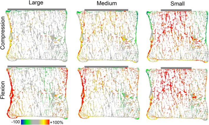
Mid‐sagittal cross section (0.25 mm thick) showing the percent difference in von Mises stress between the intact disc model and metallic implant models in compression (top) and flexion (bottom). Other implant materials were omitted for clarity. Positive differences denote higher stresses for the implant models compared to the intact disc
In compression, large implants caused 34 ± 1% of bone tissue to experience von Mises stress changes greater than ±50% relative to the intact model, compared with 51 ± 2% and 58 ± 0% of bone tissue for medium and small implants, respectively (material median ± range). In flexion, on the other hand, large implants caused 57 ± 3% of bone tissue to experience von Mises stress changes greater than ±50% relative to the intact model, compared with 51 ± 1% and 53 ± 8% for medium and small implants, respectively (material median ± range).
4. DISCUSSION
These results indicate that the presence of a TDA implant can substantially alter cortical‐trabecular load‐sharing, the spatial distribution of high‐risk tissue, and stress in bone tissue throughout the vertebral body relative to an intact disc. Implant size has a larger effect on these alterations than implant material in both compression and flexion‐induced anterior impingement. The differences in load‐transfer behavior between the intact model and the implant models were much larger for flexion‐induced anterior impingement than for compression. In other words, flexion to the point of impingement with an implant caused much larger deviations from the natural biomechanical environment compared to compression with an implant. Specifically, flexion with an implant caused local increases in stress anteriorly and shifted the tissue at the highest risk of failure to local anterior regions. This behavior was accentuated as implant size increased but did not depend much on implant material properties.
The medium implant in our study is of particular interest because it is most representative of devices used clinically: the dimensions of the implant and dimensional mismatch between the implant and the underlying vertebra are both within the range found clinically.49 Our results suggest that implants of this size recruit less overall cortical bone than the intact disc in compression, thereby overloading the trabecular centrum, at nearly all axial positions in the vertebra. For flexion‐induced anterior impingement, the medium implant substantially elevated load in the anterior cortex and anterior trabecular centrum relative to flexion with the intact disc (>100% change in minimum principal and von Mises stress) and concentrated the tissue at the highest risk of failure anteriorly. Thus, we conclude that most TDA implants, regardless of their overall stiffness properties, will diminish the load‐bearing role of the cortical shell in compression, rely more on anterior trabecular regions and the anterior cortex to resist the loads that develop in flexion, and otherwise re‐distribute stress in a large portion of the underlying vertebral body. Further, the large increases in stress and anterior concentration of high‐risk tissue in flexion suggests that, for implants of this size, bending to the point of impingement may be a causal factor for subsidence in vivo.
The mechanisms underlying the anterior shift in high‐risk tissue and the elevated stresses in the anterior cortex when the medium and large implants are loaded in flexion relate to the boundary conditions induced by impingement. For a given implant size, the stress distribution was impacted much more by the boundary condition (compression vs flexion‐induced anterior impingement) than by the implant's material properties. Impingement, defined as contact between secondary, nonbearing surfaces50 (eg, between the rim of the articulating insert and the metallic footplate, or between two metallic footplates) has been reported to occur in 9% to 66% of cases34, 51, 52 and has been documented for nearly all major device designs (Charité,52, 53, 54 ProDisc‐L,34, 51, 55 activL,36, 41 MobidiscL41). When impingement occurs, large loads can be transmitted through the impinged region.35, 37, 39, 53 Both anterior and posterior impingement are possible for flexion and extension, respectively.34, 37, 39, 51, 55 Our data show that for anterior impingement induced by flexion, the anterior portions of the cortex and underlying trabecular bone must accommodate nearly all of the load for medium and large implants. This shifts the tissue at the highest risk of initial failure to regions adjacent to the impingement. For small implants, the anterior cortex is not involved in load‐redistribution induced by flexion.
The geometric detail with which we modeled the vertebral body supporting a TDA implant is novel and enables insight that both complements and extends prior understanding. The impact of implant size has been previously explored by Auerbach et al19 using pressure film analysis; they found that larger implants decrease contact stress at the bone‐implant interface in axial compression compared with smaller implants. Their representative pressure film data appear similar to our results for a similarly sized implant with respect to the magnitude and spatial distribution of axial stress at the endplate (after linear scaling to an equivalent applied force), thus providing external experimental support for the validity of our model. Their results, however, are limited to the analysis of stress for a single loading mode (axial compression) at a superficial region (the bone‐implant interface). In contrast, a strength of this study is the elucidation of the stress distribution throughout the vertebral bone tissue as a function of implant size, as well as the interaction between implant size and loading mode. Rundell et al45 used a quantitative‐computed tomography‐based finite element model to assess the impact of axial compression, flexion/extension, and lateral bending on vertebral body strains. Their data, like ours, suggest that extensive strain redistribution within the vertebral body can occur following TDA for implants of normal clinical size, regardless of loading mode. In particular, they found anterior strain maxima following flexion with an implant which did not occur for flexion with an intact disc, thus corroborating one of the findings of our study. However, their finite element approach employed elements with 1 mm edge lengths, thereby modeling the vertebral body as an analogous continuum structure and not one comprised of a trabecular structure. While the former may be sufficient to assess macroscopic properties such as vertebral body strength, the latter is more realistic in estimating actual physiologic behavior. Further, their boundary conditions included fully fixing the inferior endplate, which neglects the impact of the adjacent disc on strains within the vertebral body. Prior studies have shown that fixing the inferior endplate [eg, potting in poly (methyl methacrylate) (PMMA)], will result in a different stress distribution within the vertebra than when loaded via an intact disc.21 Thus, their reported strain distributions may better approximate in vitro experiments in which the vertebral body is potted in PMMA as opposed to in vivo behavior in which the bone is loaded inferiorly via a disc, as was done here. Taken together, the fidelity with which we modeled the spatially variable trabecular microstructure and thin cortical shell and endplate, combined with our combination of implant size, material parameters, and boundary conditions, provides unique insight into the mechanical behavior of the human lumbar vertebral body for this class of implants.
The primary limitations of this study are its use of just a single vertebra and its theoretical nature. Micro‐architectural parameters, such as BV/TV, vary between specimens and can impact mechanical behavior.48 However, studies on n = 2221 and n = 1327 nonosteoporotic human vertebrae show a consistent pattern of cortical‐trabecular load‐sharing, which was also exhibited by the vertebra studied here. Thus, our results should likely extend to most nonosteoporotic vertebrae, though a larger sample size is necessary to confirm their generality. A substantially lower BV/TV representative of osteoporosis might result in different behavior, since structural redundancy is lost with osteoporosis.56 In part, this may help explain the contraindication of TDA for osteoporotic patients.
A second limitation stems from the purely computational nature of our study. The finite element approach used here has been shown to accurately predict whole vertebral‐body and trabecular‐core strength compared to experimental values, implying that the dominant structural mechanisms in the bone are well‐captured.48, 56 We also modeled the disc as a homogenous isotropic elastic material, thereby neglecting the details of the gelatinous nucleus pulposus and lamellar annulus fibrosus. However, with degeneration, compressive loads are thought to transmit directly through the annulus57 as the nucleus shifts from a fluid‐like to solid‐like structure.58 Thus, in terms of loads experienced by the vertebral body, the annulus‐type material properties we assigned to the disc should reasonably simulate a state of disc degeneration associated with the aged nature of the vertebra. Further, our prediction of the high‐risk tissue distribution for the intact model is consistent with the location of bone failure observed for cadaveric vertebrae loaded via degenerated discs.59, 60 Finally, our implant model omitted the protrusions (such as the spikes or teeth used for fixation) found on real implants. A sensitivity study (Appendix A) indicated that using a higher fidelity implant model that includes protrusions had a negligible effect on reported results and would not alter our conclusions. However, some implants utilize a keel instead of a series of teeth for fixation. Since these keels are much larger than the protrusions modeled here and can extend deep into the vertebral body, it is possible that keeled implants could exhibit fundamentally different behavior than that reported here. Therefore, interpretation of our results should be limited to nonkeeled implants.
We created a planar surface superiorly to replicate a TDA procedure,28 which included resection through parts of the osseous endplate. There is clinical agreement that the osseous endplate should be preserved and that only the disc and cartilaginous endplate should be resected during TDA.28, 29 However, we found it was not possible to create a planar surface without resecting parts of the osseous endplate due to its inherent irregularity. This raises the question of whether complete endplate preservation might have enabled the implants to better replicate the intact model. Results from a prior study (n = 5 L1 vertebrae) indicate that, compared with full endplate preservation, full endplate resection only minorly altered maximum cortical load fraction (decrease of 4%, P < .01) and had a similarly small effect on high‐risk tissue distribution.61 Therefore, we do not believe that resection had a large effect on our results. Some endplate resection may be clinically relevant, since the extent to which the cartilaginous endplate (approximately 0.80 mm thick62, 63) can be intra‐operatively resected while fully preserving the osseous endplate (approximately 0.50 mm thick64) is unclear. While preserving all of the osseous endplate would result in a slightly larger cortical load fraction, this would not alter our conclusions.
Despite these limitations, our results may have clinical implications. Clinical evidence suggests an etiologic link between implant subsidence and implant impingement.35, 36, 41, 54 However, the mechanisms underlying this phenomenon are not understood. It has been suggested (but not experimentally demonstrated) that the implant subsidence causes impingement.35, 36, 40, 41 In other words, it is been suggested that the implant position changes following subsidence which then increases its proclivity to impinge. However, our data suggest the opposite is also feasible ‐ that impingement causes subsidence. We found that flexion‐induced anterior impingement substantially increased stress in the bone and concentrated the high‐risk tissue to local anterior regions. The 800 N force we applied in both compression and bending (approximately 1× body weight30) facilitated comparison between models since it enabled us to isolate the interaction between size and loading mode. However, the forces on the vertebral body generated in vivo during flexion can be two to three times body weight,31, 33 since the moment arm caused by the weight of the trunk must be balanced by increasing forces in the erector spinae muscles,65 which increases the reaction force at the vertebra. Scaling the values of stress in flexion 2‐ to 3‐fold to those better representing the in vivo environment (permitted by the linear elastic nature of our study) would generate tissue‐level stresses high enough to be of concern for both monotonic and fatigue‐related tissue failure.66 The failure of the bone tissue supporting an implant may be a causal factor for implant subsidence. Therefore, if the magnitude and distribution of tissue‐level stress reported here are similar to those which develop in vivo, implants designs which impinge may inherently be at risk of overloading the bone in the regions near the impingement. We suggest that benchtop subsidence tests should incorporate bending‐induced impingement to better replicate in vivo behavior.
In summary, our findings suggest that implant size has a larger effect on load‐transfer behavior within the vertebral body than implant material in both compression and flexion.
If impingement following flexion occurs in vivo, local stresses in the bone tissue can substantially increase anteriorly in the region adjacent to the impingement. This behavior is accentuated as implant size increases. For the medium implant, whose size is similar to those used clinically, these elevated stresses are sufficiently high to warrant concern for monotonic or fatigue‐related bone failure, which may contribute to clinically observed implant subsidence.
CONFLICT OF INTEREST
N.B.—none. T.K.—consultant, O.N. Diagnostics; equity, O.N. Diagnostics; consultant, Amgen.
AUTHOR CONTRIBUTIONS
N.B.—study design, data collection, data analysis, and manuscript preparation. T.K.—study design, data analysis, and manuscript preparation.
Supporting information
Figure S1. The cortical load fraction (left) and high‐risk tissue volume (right) were not sensitive to our choice of tissue material properties within a realistic physiologic range or the addition of small implant protrusions
ACKNOWLEDGMENTS
The authors acknowledge the Texas Advanced Computing Center at The University of Texas at Austin for providing computational resources that have contributed to the research results reported within this paper. The authors also acknowledge Professor X. Edward Guo at Columbia University for the μCT data.
APPENDIX A 1.
To assess the impact of footplate protrusions (such as spikes or teeth to facilitate fixation into the vertebral body) on our outcomes, we conducted a sensitivity study in which we added six 1.5 mm wide by 3 mm deep cylindrical protrusions to the medium size, metallic implant and loaded the implant in compression and flexion. The protrusions were added in an elliptical pattern resembling that of the Charité implant. Relative to the medium size, metallic implant without protrusions, the cortical load‐fraction varied by a maximum of 1.9% at any axial location and the high‐risk tissue volume varied by a maximum of 2.7% at any A/P location (Figure S1). The 98th percentile of axial stress varied by a maximum of 1.8% and the amount of bone tissue with von Mises stress changes greater than ±50% varied by a maximum of 1.0%. Thus, the addition of small protrusions resembling the spikes or teeth present on clinically used implants should have an insignificant effect on our reported results and would not alter our conclusions.
APPENDIX B 1.
To account for uncertainty in our assumption of bone tissue material properties (elastic modulus of 10.3 GPa, Poisson's ratio 0.30), we performed a sensitivity study on the intact model in which bone tissue was modeled using another possible physiologic value of material properties (elastic modulus of 18.5 GPa, Poisson's ratio of 0.3027). The load‐sharing outcomes were insensitive to our choice of bone tissue material properties over the range tested. The cortical load‐fraction varied by a maximum of 0.5% and the high‐risk tissue volume varied by a maximum of 1% at any axial location (Figure S1). Thus, the error of our load‐sharing estimates with respect to our choice of bone tissue elastic modulus are negligible.
Bonnheim NB, Keaveny TM. Load‐transfer in the human vertebral body following lumbar total disc arthroplasty: Effects of implant size and stiffness in axial compression and forward flexion. JOR Spine. 2020;3:e1078 10.1002/jsp2.1078
Funding information The University of Texas at Austin
REFERENCES
- 1. Weinstein J, Lurie J, Olson P, et al. United States trends and regional variations in lumbar spine surgery. Spine (Phila Pa 1976). 2006;31(23):2707‐2714. [DOI] [PMC free article] [PubMed] [Google Scholar]
- 2. Yavin D, Casha S, Wiebe S, et al. Lumbar fusion for degenerative disease: a systematic review and meta‐analysis. Neurosurgery. 2017;80(5):701‐715. [DOI] [PubMed] [Google Scholar]
- 3. Etebar S, Cahill D. Risk factors for adjacent‐segment failure following lumbar fixation with rigid instrumentation for degenerative instability. J Neurosurg Spine. 1999;90(2):163‐169. [DOI] [PubMed] [Google Scholar]
- 4. Goffin J, Geusens E, Vantomme N, et al. Long‐term follow‐up after interbody fusion of the cervical spine. J Spinal Disord Tech. 2004;17(2):79‐85. [DOI] [PubMed] [Google Scholar]
- 5. Lee C. Accelerated degeneration of the segment adjacent to a lumbar fusion. Spine (Phila Pa 1976). 1988;13(3):375‐377. [DOI] [PubMed] [Google Scholar]
- 6. Formica M, Divano S, Cavagnaro L, et al. Lumbar total disc arthroplasty: outdated surgery or here to stay procedure? J Orthop Traumatol. 2017;18(3):197‐215. [DOI] [PMC free article] [PubMed] [Google Scholar]
- 7. Link H, Keller A. Biomechanics of total disc replacement In: Bütner‐Janz K, Hochschuler S, McAfee P, eds. The Artificial Disc. Berlin, Germany: Springer; 2003:33‐52. [Google Scholar]
- 8. McKenzie A. The basis for motion preservation surgery In: Yue J, Bertagnoli R, An H, eds. Motion Preservation Surgery of the Spine. Philadelphia, PA: Saunders; 2008:3‐10. [Google Scholar]
- 9. Galbusera F, Bellini C, Zweig T, et al. Design concepts in lumbar total disc arthroplasty. Eur Spine J. 2008;17:1635‐1650. [DOI] [PMC free article] [PubMed] [Google Scholar]
- 10. Jin Y, Park S, Kim M, et al. An analysis of heterotopic ossification in cervical disc arthroplasty. Spine J. 2013;13:408‐420. [DOI] [PubMed] [Google Scholar]
- 11. Putzier M, Funk J, Schneider S, et al. Charité total disc replacement: clinical and radiographical results after an average follow‐up of 17 years. Eur Spine J. 2006;15:183‐195. [DOI] [PMC free article] [PubMed] [Google Scholar]
- 12. Park S, Kang K, Shin S, et al. Heterotopic ossification following lumbar total disc replacement. Int Orthop. 2011;35(8):1197‐1201. [DOI] [PMC free article] [PubMed] [Google Scholar]
- 13. Shim C, Lee S, Maeng D, et al. Vertical split fracture of the vertebral body following total disc replacement using ProDisc. J Spinal Disord Tech. 2005;18(5):465‐469. [DOI] [PubMed] [Google Scholar]
- 14. Datta J, Janssen M, Beckham R, et al. Sagittal split fractures in multilevel cervical arthroplasty using a keeled prosthesis. J Spinal Disord Tech. 2007;20(1):89‐92. [DOI] [PubMed] [Google Scholar]
- 15. Tu T, Wu J, Fay L, et al. Vertebral body split fracture after a single‐level cervical total disc replacement. J Neurosurg Spine. 2012;16:231‐235. [DOI] [PubMed] [Google Scholar]
- 16. Punt I, van Rijsbergen M, van Rietbergen B, et al. Subsidence of SB Charité total disc replacement and the role of undersizing. Eur Spine J. 2013;22:2264‐2270. [DOI] [PMC free article] [PubMed] [Google Scholar]
- 17. Punt I, Visser V, van Rhijn L, et al. Complications and reoperations of the SB Charité lumbar disc prosthesis. Eur Spine J. 2008;17:36‐43. [DOI] [PMC free article] [PubMed] [Google Scholar]
- 18. Lu S, Sun S, Kong C, et al. Long‐term clinical results following Charite III lumbar total disc replacement. Spine J. 2018;18(6):917‐925. [DOI] [PubMed] [Google Scholar]
- 19. Auerbach J, Ballester C, Hammond F, et al. The effect of implant size and device keel on vertebral compression properties in lumbar total disc replacement. Spine J. 2010;10(4):333‐340. [DOI] [PubMed] [Google Scholar]
- 20. Tan J, Bailey C, Dvorak M, et al. Interbody device shape and size are important to strengthen the vertebra‐implant interface. Spine (Phila Pa 1976). 2005;30(6):638‐644. [DOI] [PubMed] [Google Scholar]
- 21. Yang H, Nawathe S, Fields A, et al. Micromechanics of the human vertebral body for forward flexion. J Biomech. 2012;45(12):2142‐2148. [DOI] [PMC free article] [PubMed] [Google Scholar]
- 22. Fields A, Eswaran S, Jekir M, et al. Role of trabecular microarchitecture in whole‐vertebral body biomechanical behavior. J Bone Miner Res. 2009;24(9):1523‐1530. [DOI] [PMC free article] [PubMed] [Google Scholar]
- 23. Issever A, Walsh A, Lu Y, et al. Micro‐computed tomography evaluation of trabecular bone structure on loaded mice tail vertebrae. Spine (Phila Pa 1976). 2003;28(2):123‐128. [DOI] [PubMed] [Google Scholar]
- 24. Sandino C, McErlain D, Schipilow J, et al. The poro‐viscoelastic properties of trabecular bone: a micro computed tomography‐based finite element study. J Mech Behav Biomed Mater. 2015;44:1‐9. [DOI] [PubMed] [Google Scholar]
- 25. Verhulp E, van Rietbergen B, Müller R, Huiskes R. Indirect determination of trabecular bone effective tissue failure properties using micro‐finite element simulations. J Biomech. 2008;41(7):1479‐1485. [DOI] [PubMed] [Google Scholar]
- 26. Legrand E, Chappard D, Pascaretti C, et al. Trabecular bone microarchitecture, bone mineral density, and vertebral fractures in male osteoporosis. J Bone Miner Res. 2000;15(1):13‐19. [DOI] [PubMed] [Google Scholar]
- 27. Eswaran S, Gupta A, Adams M, Keaveny TM. Cortical and trabecular load sharing in the human vertebral body. J Bone Miner Res. 2006;21(2):307‐314. [DOI] [PubMed] [Google Scholar]
- 28. Jaramillo J, Yue J. Disc space preparation techniques for lumbar disc arthroplasty In: Yue J, Bertagnoli R, McAfee P, An H, eds. Motion Preservation Surgery of the Spine. Philadelphia, PA: Saunders; 2008:305‐308. [Google Scholar]
- 29. Geisler F. Surgical technique of lumbar artificial disc replacement with the Charité artificial disc. Neurosurgery. 2005;56:46‐57. [DOI] [PubMed] [Google Scholar]
- 30. Dey D, Rothenberg E, Sundh V, et al. Height and body weight in elderly adults: a 21‐year population study on secular trends and related factors in 70‐year‐olds. J Gerontol. 2001;56A(12):780‐784. [DOI] [PubMed] [Google Scholar]
- 31. Dreischarf M, Shirazi‐Adl A, Arjmand N, Rohlmann A, Schmidt H. Estimation of loads on human lumbar spine. J Biomech. 2016;49(6):833‐845. [DOI] [PubMed] [Google Scholar]
- 32. Adams M, Pollintine P, Tobias J, et al. Intervertebral disc degeneration can predispose to anterior vertebral fractures in the thoracolumbar spine. J Bone Miner Res. 2006;21(9):1409‐1416. [DOI] [PubMed] [Google Scholar]
- 33. Rohlmann A, Claes L, Bergmann G, et al. Comparison of intradiscal pressures and spinal fixator loads for different body positions and exercises. Ergonomics. 2001;44(8):781‐794. [DOI] [PubMed] [Google Scholar]
- 34. Käfer W, Clessienne C, Däxle M, et al. Posterior component impingement after lumbar total disc replacement. Spine (Phila Pa 1976). 2008;33(22):2444‐2449. [DOI] [PubMed] [Google Scholar]
- 35. Kurtz S, van Ooij A, Ross R, et al. Polyethylene wear and rim fracture in total disc arthroplasty. Spine J. 2007;7:12‐21. [DOI] [PubMed] [Google Scholar]
- 36. Grupp T, Yue J, Garcia R, et al. Evaluation of impingement behaviour in lumbar spinal disc arthroplasty. Eur Spine J. 2015;23:2033‐2046. [DOI] [PubMed] [Google Scholar]
- 37. Siskey R, Peck J, Mehta H, Kosydar A, Kurtz S, Hill G. Development of a clinically relevant impingement test method for a mobile bearing lumbar total disc replacement. Spine J. 2016;16(9):1133‐1142. [DOI] [PubMed] [Google Scholar]
- 38. Rundell S, Day J, Isaza J, et al. Lumbar total disc replacement impingement sensitivity to disc height distraction, spinal sagittal orientation, implant position, and implant lordosis. Spine (Phila Pa 1976). 2012;37(10):E590‐E598. [DOI] [PubMed] [Google Scholar]
- 39. Rundell S, Day J, Isaza J, et al. Derivation of clinically relevant boundary conditions suitable for evaluation of chronic impingement of lumbar total disk replacement. J ASTM Int. 2011;8(5):73‐94. [Google Scholar]
- 40. Kurtz S, Siskey R, Ciccarelli L, et al. Retrieval analysis of total disc replacements: implications for standardized wear testing. J ASTM Int. 2006;3(6):53‐64. [Google Scholar]
- 41. Austen S, Punt I, Cleutjens J, et al. Clinical, radiological, histological and retrieval findings of Activ‐L and Mobidisc total disc replacements: a study of two patients. Eur Spine J. 2012;21(suppl 4):S513‐S520. [DOI] [PMC free article] [PubMed] [Google Scholar]
- 42. Bevill G, Eswaran S, Farahmand F, et al. The influence of boundary conditions and loading mode on high‐resolution finite element‐computed trabecular tissue properties. Bone. 2009;44(4):573‐578. [DOI] [PubMed] [Google Scholar]
- 43. Yang H, Jekir M, Davis M, et al. Effective modulus of the human intervertebral disc and its effect on vertebral bone stress. J Biomech. 2016;49(7):1134‐1140. [DOI] [PMC free article] [PubMed] [Google Scholar]
- 44. Dooris A, Goel V, Grosland N, et al. Load‐sharing between anterior and posterior elements in a lumbar motion segment implanted with an artificial disc. Spine (Phila Pa 1976). 2001;26(6):E122‐E129. [DOI] [PubMed] [Google Scholar]
- 45. Rundell S, Auerbach J, Balderston R, et al. Total disc replacement positioning affects facet contact forces and vertebral body strains. Spine (Phila Pa 1976). 2008;33(23):2510‐2517. [DOI] [PubMed] [Google Scholar]
- 46. Adams MF, Bayraktar HH, Keaveny TM, Papadopoulos P. Ultrascalable implicit finite element analysis in solid mechanics with over half a billion degrees of freedom Proceedings of the ACM/IEEE SC2004 Conference: High Performance Networking and Computing. Pittsburgh, PA: IEEE; 2004:1‐15. [Google Scholar]
- 47. Pruitt L, Chakravartula A. Orthopedics Mechanics of Biomaterials. New York, NY: Cambridge University Press; 2011:416‐476. [Google Scholar]
- 48. Bevill G, Eswaran S, Gupta A, et al. Influence of bone volume fraction and architecture on computed large‐deformation failure mechanisms in human trabecular bone. Bone. 2006;39(6):1218‐1225. [DOI] [PubMed] [Google Scholar]
- 49. Michaela G, Denise H, Liebensteiner M, Michael BC. Footprint mismatch in lumbar total disc arthroplasty. Eur Spine J. 2008;17:1470‐1475. [DOI] [PMC free article] [PubMed] [Google Scholar]
- 50. ASTM . ASTM F2423−11 (2016): Standard guide for functional, kinematic, and wear assessment of total disc prostheses. ASTM Int. 2016: 1‐10. [Google Scholar]
- 51. Lebl D, Cammisa F, Girardi F, et al. In vivo functional performance of failed Prodisc‐L devices. Spine (Phila Pa 1976). 2012;37(19):E1209‐E1217. [DOI] [PubMed] [Google Scholar]
- 52. Kurtz S, Patwardhan A, MacDonald D, et al. What is the correlation of in vivo wear and damage patterns with in vitro TDR motion response? Spine (Phila Pa 1976). 2008;33(5):481‐489. [DOI] [PMC free article] [PubMed] [Google Scholar]
- 53. Baxter R, MacDonald D, Kurtz S, et al. Severe impingement of lumbar disc replacements increases the functional biological activity of polyethylene wear debris. J Bone Jt Surg. 2013;75(95):e75 (1–9). [DOI] [PMC free article] [PubMed] [Google Scholar]
- 54. van Ooij A, Kurtz S, Stessels F, et al. Polyethylene wear debris and long‐term clinical failure of the Charité disc prosthesis. Spine (Phila Pa 1976). 2007;32(2):223‐229. [DOI] [PubMed] [Google Scholar]
- 55. Choma T, Miranda J, Siskey R, et al. Retrieval analysis of a ProDisc‐L total disc replacement. J Spinal Disord Tech. 2009;22(4):290‐296. [DOI] [PubMed] [Google Scholar]
- 56. Fields A, Nawathe S, Eswaran S, et al. Vertebral fragility and structural redundancy. J Bone Miner Res. 2012;27(10):2152‐2158. [DOI] [PMC free article] [PubMed] [Google Scholar]
- 57. Bartel D, Davy D, Keaveny T. Orthopedic Biomechanics: Mechanics and Design in Musculoskeletal Systems. Upper Saddle River, NJ: Pearson Prentice Hall Bioengineering; 2006:140‐147. [Google Scholar]
- 58. Iatridis J, Setton L, Weidenbaum M, et al. Alterations in the mechanical behavior of the human lumbar nucleus pulposus with degeneration and aging. J Orthop Res. 1997;15:318‐322. [DOI] [PubMed] [Google Scholar]
- 59. Jiang G, Luo J, Pollintine P, Dolan P, Adams MA, Eastell R. Vertebral fractures in the elderly may not always be “osteoporotic”. Bone. 2010;47(1):111‐116. [DOI] [PubMed] [Google Scholar]
- 60. Farooq N, Park J, Pollintine P, et al. Can vertebroplasty restore normal load‐bearing to fractured vertebrae? Spine (Phila Pa 1976). 2005;30(15):1723‐1730. [DOI] [PubMed] [Google Scholar]
- 61. Bonnheim N, Verbiest V, Wu T, et al. Total disc replacement implants affect load‐transfer throughout the vertebral body with and without endplates. Paper presented at: Orthopedic Research Society Conference; 2019; Austin, TX.
- 62. Moon S, Yoder J, Wright A, et al. Evaluation of intervertebral disc cartilaginous endplate structure using magnetic resonance imaging. Eur Spine J. 2013;22(8):1820‐1828. [DOI] [PMC free article] [PubMed] [Google Scholar]
- 63. Berg‐Johansen B, Han M, Fields A, et al. Cartilage endplate thickness variation measured by ultrashort echo‐time MRI is associated with adjacent disc degeneration. Spine (Phila Pa 1976). 2018;43(10):E592‐E600. [DOI] [PMC free article] [PubMed] [Google Scholar]
- 64. Silva M, Wang C, Keaveny T, et al. Direct and computed tomography thickness measurements of the human, lumbar vertebral shell and endplate. Bone. 1994;15(4):409‐414. [DOI] [PubMed] [Google Scholar]
- 65. White A, Panjabi M. Physical properties and functional biomechanics of the spine Clinical Biomechanics of the Spine. 2nd ed. Philadelphia, PA: J.B. Lippincott Company; 1990:1‐83. [Google Scholar]
- 66. Choi K, Goldstein S. A comparison of the fatigue behavior of human trabecular and cortical bone tissue. J Biomech. 1992;25(12):1371‐1381. [DOI] [PubMed] [Google Scholar]
Associated Data
This section collects any data citations, data availability statements, or supplementary materials included in this article.
Supplementary Materials
Figure S1. The cortical load fraction (left) and high‐risk tissue volume (right) were not sensitive to our choice of tissue material properties within a realistic physiologic range or the addition of small implant protrusions