Abstract
The two dimensional molecular tagging velocimetry (2D-MTV) has been used to measure velocity fields of the flow in a micro mixer. Instead of commonly used micro particles an optical tagging of the flow has been performed by using a caged dye. The pattern generation is done by imaging a mask for the first time. This allows to generate nearly any imaginable pattern. The flow induces a deformation of the optically written pattern that can be tracked by laser induced fluorescence. The series of raw images acquired in this way were analyzed quantitatively with a novel optical flow based technique. The reference measurements have been carried out allowing to draw conclusions about the accuracy of this procedure. A comparison to the standard technique of μPIV has also been conducted. Apart from measuring flow velocities in microfluidic mixing processes, the spatial distribution of concentration fields for different species has also been measured. To this end, a new technique has been developed that allows spatial measurements from Planar Spontaneous Raman Scattering (PSRS). The Raman stray light of the relevant species has been spectrally selected by a narrow bandpass filter and thus detected unaffectedly by the Raman stray light of other species. The successful operation of this measurement procedure in micro flows will be demonstrated exemplary for a mixing process of water and ethanol.
Keywords: Vector Field, Optical Flow, Microfluidic System, Velocity Vector Field, Raman Imaging
Introduction
Over the past few years, microfluidic systems have experienced a rapid development. Technological advancements in the manufacturing processes of microfluidic components have opened new pathways for a broad variety of technical applications (Erickson and Li 2004). Especially chemical and biochemical analysis as well as medical diagnostics, where often only tiny sample amounts are available, strongly benefit from small system volumes and substantially faster analysis times enabled by microfluidic technologies (Burns and Ramshaw 2001; Lai et al. 2004; Nguyen and Wereley 2002). The application of microfluidic systems improved handling and analysis times of DNA sequence tests (Paege et al. 2001; Srinivasan et al. 2004; Wang 2000) and led to improved detection systems for viruses like SARS (Zhou et al. 2004). Recently, microfluidic systems also became interesting for chemical production processes. In particular the possibility to precisely define and control the physical boundary conditions inside micro channels with a huge surface to volume ratio leads to more efficient production processes with much less by-products. Due to the strongly increasing interest in microfluidic devices there is a growing demand for new diagnostic tools for the analysis of flow structures, mixture formation and reaction behavior directly inside the micro channels. In particular non-intrusive measurement techniques which do not influence the flow and reaction processes in the channels are badly needed. Several reviews are concerned with miscellaneous detection techniques (Mogensen et al. 2004; Sinton 2004; Viskari and Landers 2005). The present work covers the development of two procedures, which provide comprehensive information about microfluidic flows.
Micro mixers
Production processes as well as many detection methods assume reactions and thus a perfect mixing of the involved chemicals. In the dimensions of microfluidics, mixing processes are based on diffusion only. This is due to the small system sizes and slow flow velocities. Hence, mixing occurs very ineffectively and slowly. In the last years, the development of countless techniques to accelerate and improve mixing was promoted. A recent review about different available types of micro mixers outlines what is possible today (Nguyen and Wu 2005). In the following sections two different measurement procedures will be described which have unique requirements. Therefore, two different concepts of micro mixers were used to fulfill these requirements. The first microfluidic system is shown in Fig. 1. It was used for the velocity measurements. Flow measurements conducted in the mixing chamber of an active micro mixer will be presented in Sect. 3.1 later.
Fig. 1.
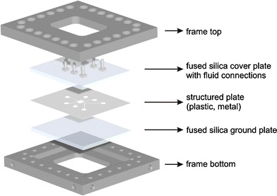
Sandwich concept of a planar micro mixer
The sandwich concept allows the change of microfluidic geometries very fast by replacing the middle layer. In this case the used micro geometries were etched into 200 μm thick plates of stainless steel. An optimal optical access to the micro channels is achieved through the use of fused silica plates that cover the structured plate. The top plate contains several drill holes which lead to the fluidic connections. The three layers are compressed by a stainless steel frame to seal the channels. A cleaning of the glass plates or the channels can be done easily with this concept.
The second micro mixer was developed and provided by the Institute for Micro Process Engineering of the Research Center Karlsruhe in Germany. This passive micro mixer is shown in Fig. 2. The mixing concept is a multi lamination of several filaments of the two fluids. This mixer was used for the development of the spatial concentration measurements based on Raman spectroscopy. The fluidic connections can be seen at the bottom of the mixer. The lamination is done by a metal bar in the middle with many micro milled channels. At the outlet the two fluids are arranged in a chessboard style as shown to the left. In the present context, the cross section of one outlet measures 1 mm × 1 mm. For technical applications, a more relevant mixer would consist of many more channels. Here a simpler set-up was used to better demonstrate our novel technique of concentration measurements. The mixing region is surrounded by a top and bottomless cuvette of fused silica. This grants optical access from all directions. The size of the cuvette is 10 mm × 10 mm × 40 mm. The modular assembly of the mixer allows easy cleaning and change of the lamination geometry or replacement of the cuvette.
Fig. 2.
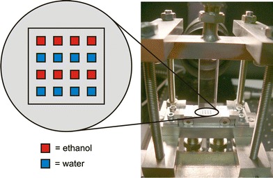
Multi lamination mixer with chessboard style outlet geometry and mixing region in an optical transparent cuvette of fused silica
Flow visualization
One of the most important informations needed to understand microfluidic processes is the actual flow field. The measurement of flow velocities can be done by several different procedures (Inaba et al. 2001; Santiago et al. 1998; Shinohara et al. 2004). In many cases the widely spread μPIV is used. An alternative is the so called “molecular tagging velocimetry” (MTV). In microfluidic flows line tagging is commonly used which can only provide information about the flow velocities along and perpendicular to the tagged line (Lempert and Harris 2000; Lempert et al. 1995; Maynes and Webb 2002; Mosier et al. 2002; Paul et al. 1998). Two dimensional approaches (Gendrich et al. 1997; Koochesfahani and Nocera 2001; Krüger et al. 2000; Stier and Koochesfahani 1999) have not been tested for micro flows until recently. Besides the application of two dimensional MTV on microfluidic flows, two main aspects differ from previsious approaches. The tagging procedure presented here is far more variable than commonly used line tagging. Imaging a mask allows to adapt the tagging pattern to the flow and nearly every imaginable pattern can be created. The second important improvement is the combination of this tagging procedure with an optical flow based evaluation algorithm. The algorithm is furthermore adapted to the measurement procedure.
Flow field analysis by 2D-MTV
In contrast to proven procedures such as PIV or PTV, no seeding particles were used as flow markers for the determination of velocity vector fields of the flow. Instead, the flow was tagged by structured illumination of a fluorescence dye and the pattern written this way was visualized time resolved by a camera. The tagging is possible by a chemical modification of dye molecules. Initially, the fluorescence ability of the dye is deactivated by an additional functional group bonded to the molecule, thus these dyes are called “caged dyes” (Gee et al. 2001). UV light is able to crack the chemical bond of this functional group, so that the original unaltered dye is present again. If an UV laser pulse is spatially structured by imaging a mask, a well defined pattern of the original dye within the caged dye loaded flow can be generated. The dye can now be excited with a further laser to fluoresce and the spatial fluorescence pattern can be read time resolved by a camera. The dye is moving with the fluid flow during the acquisition and the written pattern can be used as marker for the velocity evaluation. The image sequences grabbed this way were evaluated by a special algorithm in regard to the flow velocities. The dye diffuses in the fluid and for this reason the written patterns are washed-out in a temporal sequence. Hence classical correlation algorithms as used for PIV are only suitable to a limited extent. Instead a specially adapted gradient based optical flow (OF) estimation technique was used (Garbe 2006; Garbe et al. 2007b, 2006). Informations about OF in general can be found in (Barron et al. 1994; Garbe et al. 2003; Haußecker and Fleet 2001; Jähne 2005). Only a brief description of the optical flow estimation technique will be given here. For standard techniques, the basal assumption for the evaluation is a constant gray value. This assumption, frequently violated in visualizing microfluidic flows, can be extended to incorporate dynamical changes of gray values, based on transport processes (Garbe et al. 2007a, b, 2003). Specifically, the effect of Taylor dispersion can be formulated in a similar motion constraint equation. The differential equation of this constraint consists of the time gradient of the measured intensities and unknown parameters. These include the spatial shift of the gradient and it is possible to model further experimental properties as for example diffusion or irregularities of the illumination. The spatial shift can be determined by solving the equation. It is necessary to make additional assumptions to be able to solve this under-determined problem. If the fluid motion is estimated to be constant in a local neighborhood a similar equation for every pixel within the neighborhood is generated and the problem gets over-determined. This system of equations can be solved by a totally least squares approach. The intensity gradients are taken from the MTV recordings and determined by a specialized Sobel operator (Scharr 2004). For the calculation of the temporal gradient an image series of five images is used. The resulting velocity vector is arranged in the middle of this time series. In principle a vector is calculated for every single pixel. However it is not reasonable to use vectors which were calculated in areas that show nothing than noise during the whole sequence. Hence these areas are masked out by a segmentation in a post processing step. The segmentation is done by the gray value in the images so that any vector outside a dot is refused. Some further adaptions of the algorithms are necessary especially due to the taylor dispersion, which will be explained later.
Figure 3 shows the experimental setup that was used to acquire the presented results. The setup can be separated into three main parts. At first there are the fluidic components, the second consists of the optical elements for the tagging process and the third of the fluorescence excitation and detection. The object of research is located in the center of the setup. For these measurements the Sandwich-concept shown in Fig. 1 was used with either a straight channel or an active micro mixer geometry. The liquid flow inside the micro channels is driven by the gas pressure in a reservoir and controlled by precision valves. The constant gas pressure guarantees a stable and pulsation free flow. A reference measurement of the flow rates is done synchronously to the image acquisition by a flow meter (SLG 1430, Sensirion). The used fluid was demineralized water with a low concentration (500 mg/l, caged Carboxy-Q-Rhodamine, Molecular Probes) of the dissolved “caged dye”. The optical components consist of the part for generating the tagging-pattern in the fluid and a second one for excitation and detection of the fluorescence. For the flow tagging the expanded beam of a pulsed XeF-Excimerlaser (COMPex 150, Lambda Physik AG) at 351 nm and a pulse energy of 200 mJ is used for a complete illumination of a 40 mm × 40 mm mask with a well defined transmission pattern. The image of the illuminated mask is demagnified and imaged into the fluid which flows inside the planar micro mixer. In a second step an Argon-Ion laser (Innova 310, Coherent) at a wavelength of 514 nm is used to read out the deformed fluorescence pattern by continuous integral illumination of the dye doped fluid whose fluorescence ability was reactivated before by the UV-laser beam. A CCD-camera (Imager Compact QE, LaVision) images the fluorescence light of the dye pattern deformed by the flow at well defined points in time after the writing process. The camera therefore is triggered with a frequency of 10 Hz by a delay generator to guarantee a fixed time delay of 100 ms between successive images. Depending on the dimensions of the evaluated flow either a microscope objective (5×, Zeiss) or a macro objective (50 mm, Nikon) is used. The depth of focus of the macro objective is by far bigger than the depth of the micro flow channel (200 μm). The depth of focus of the microscope objective (about 50 μm) is smaller than the depth of the channel. We do not expect any effects for the optical flow evaluation if the patterns are not blurred too much. This is the case for the measurements presented here. Interfering excitation light is suppressed by an optical bandpass filter (OG570, Schott). The measurement procedure has been presented previously in (Roetmann et al. 2005, 2006a, b).
Fig. 3.
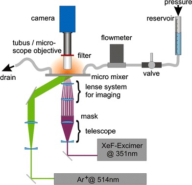
Experimental setup for 2D-MTV recordings
Figure 4 shows an image sequence that was generated by the described procedure. This is a typical example for the microfluidic flows investigated so far. The mixing chamber (5 mm × 5 mm × 200 μm) is streamed from the left to the right while the four side channels that are intended to create different flow fields in the mixer remain unused for these investigations. The mixing chamber generates a widening of the cross section of the flow. In this case a regular dot pattern was used to mark the flow. The dots have a diameter of about 160 μm after the imaging process and their period is three times the diameter.
Fig. 4.
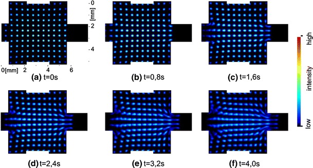
2D-MTV image series of a laminar micro flow. The original sequence was taken with 10 Hz, fewer images are shown here for a better visualization of the flow
A result of the flow analysis with OF is shown in Fig. 5. The illustrated vector field of an—in this case—stationary flow is time averaged over ten single vector fields. The vector fields were calculated from the same image sequence. A single vector field contains vectors only at positions were a dot was written into the flow like Fig. 7 shows. Since the dots are moving during the sequence, as shown in Fig. 4, the calculation of velocities is possible in almost the whole chamber. The gaps between the vectors are closing by the averaging process and nearly the entire field gets visible. This is preferable if the qualitative distribution of the vector field should be evaluated. The resulting vector field reproduces the anticipated flow field very well in the presented case.
Fig. 5.
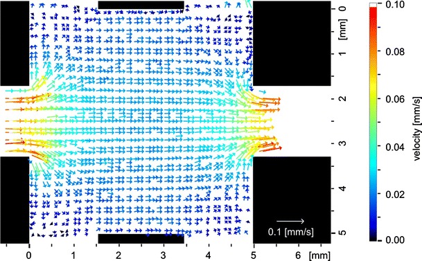
Temporally averaged velocity vector field calculated from the image series in Fig. 4
Fig. 7.
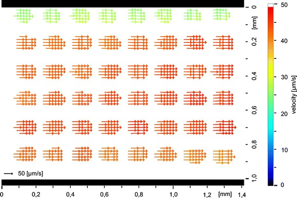
Result of a tagging measurement with evaluation by a modified optical flow algorithm in a straight channel
Reference measurements and Taylor dispersion
A disturbing effect which is particularly distinct in micro flows is the so called Taylor dispersion. It is caused by the parabolic velocity profile that is formed between top and bottom plates in a flat channel. By means of this effect the fluorescing patterns blur increasingly during the progressing flow. This issue is drafted in Fig. 6. The kind of detection, which integrates over the depth of the channel, leads to the deformation of the initially punctual pattern to a kind of “comet tail” that can be found for example in Fig. 4. The evaluation results in lower velocities in the region of the “tail” and higher ones at the front of the moving pattern. Due to the fact that the velocity values in the vector field need to be allocated to different levels in the channel it is necessary to modify the evaluation algorithms in order to calculate velocities in a certain level.
Fig. 6.
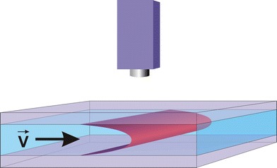
Schematic diagram of the pressure driven flow between top and ground plate
The adjustments to the algorithms could be done on condition that the flow is strictly laminar and two dimensional. A parabolic flow profile as shown in Fig. 6 leads to assumptions about the resulting velocities after the two dimensional projection when the camera view integrates through the channel depth. The parabolic flow profile is based on a laminar Poiseuille flow. This allows to extend the differential equation for the optical flow calculations to take the Taylor dispersion into account. The concrete arrangements that were used can be found in (Garbe 2006; Garbe et al. 2007b, 2006). The improvements presented there allowed to correct the errors that would result from the Taylor dispersion and calculate velocity vector fields that would match the conditions in the middle level (apex of the Taylor dispersion parable).
This enables a quantitative comparison of the calculated values with the reference values taken by the flow meter. Therefore tagging measurements in a straight channel with a rectangular profile of 1.12 mm × 200 μm were carried out. Fig. 7 shows a result of these measurements. The underlying dot pattern is clearly visible because a velocity calculation is only possible if intensity structures are visible as mentioned previously. The dots measure about 80 μm in diameter and the period is two times the diameter. The mean flow velocity was calculated from the measured velocity vector fields by a local average determination. Because of the correction of the Taylor dispersion the mean flow velocity of this vector field corresponds to the maximum velocity in the middle level of the channel. The flow meter simultaneously detected the volume flow of the fluid. These values are convertible to mean flow velocities by the known geometry of the cross section of the channel. Mean flow velocities can again be converted to the maximum flow velocities in the middle level of the channel because of the parabolic flow profile. Both maximum flow velocities, of the OF calculations on the one hand and the measurements of the flow meter on the other, should match.
Measurements in a wide range of flow velocities were used to create the comparison shown in Fig. 10. The bisecting line is plotted to show the perfect accordance of both values. Additionally, error bars calculated from the RMS of the averaged area of the vector fields were inserted. Most of the calculated values are lying within the calculated error bars and the deviation from the measurements of the flow meter is about 5%. However some values, especially higher ones, are too high if compared with a perfect match. This could be due to a bad velocity calculation or caused by wrong calibration values. A calibration is necessary to convert the time and length scales to real dimensions (for example pixel to mm) and to convert from mean to maximum velocities. The calibration is easy for the time scale. The time difference between two frames is triggered to 100 ms with a very low jitter. For the conversion of pixels to μm the channel width was used. All parameters can be determined accurately with a maximum error of 5%. Due to the fact that all these values directly scale the resulting velocities, a slight error is propagated linearly.
Fig. 10.
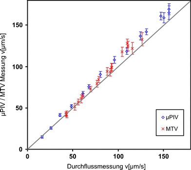
Quantitative comparison between the velocity values determined by μPIV/MTV measurements and the measurements of the flow meter
For a further comparison and to evaluate the abilities of the tagging measurements a second measurement procedure was applied to the same fluidic setup. The generally accepted method of μPIV was used for this comparison. The experimental setup shown in Fig. 8 is similar to the one used for the tagging measurements. The fluidic components are exactly the same, the setup was not disassembled between both measurements. A dark field illumination was used to minimize the detection of excitation light. By using the small depth of focus of the microscope objective (10×, Fa. Zeiss) it is possible to select a specific level in the channel. The correlation depth of the objective can be estimated as presented by Meinhardt et al. (2000). It is about 35 μm in this case, calculated for green light which is around the middle for the used white light. The optics were adjusted to measure the velocities in the middle level of the channel similar to the measurements before. Instead of the caged dye particles (1 μm diameter, mono disperse silica) were added. The particle images acquired by the camera were evaluated by a commercially available PIV Software (DaVis, Fa. LaVision) subsequent to applying a standard preprocessing procedure commonly used for μPIV evaluations. At first the minimum intensity per pixel was calculated from the time series and the resulting image was subtracted from the whole time series to eliminate background noise. Out of focus particles were removed by subtraction of a threshold. At last a standard correlation algorithm determined the particle displacements. An example of a resulting vector field is presented in Fig. 9.
Fig. 8.
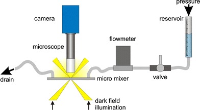
Experimental setup for μPIV recordings
Fig. 9.
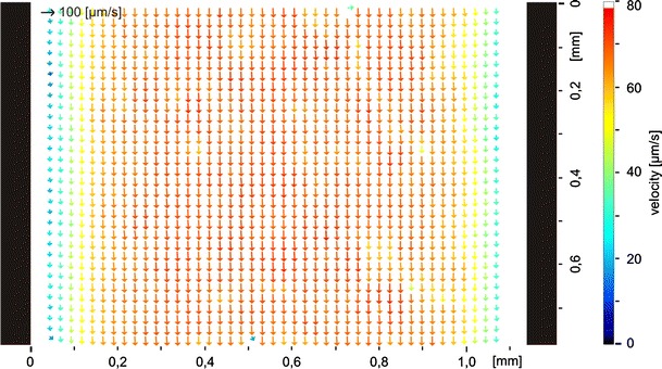
Result of a μPIV measurement in a straight channel
Again, the flow rates were measured simultaneously by the flow meter hence the same comparison as for the tagging measurements could be done. Figure 10 shows the values, the bisecting line and error bars calculated from the RMS of the vectors within the averaged area. The flow rates are again too high and a systematic deviation from the ideal values of 6% can be seen. A linear interpolation of the measured values led to a fluctuation around the interpolation line of only 2%. On the basis of the comparisons it is assumed that the systematic deviation is caused mainly by the calibration values. The evaluation by the adapted optical flow algorithm leads to reasonable results. This means a very good qualitative comparison with the expected fluid flow as shown in Sect. 3.1 and good quantitative accordance with standard μPIV, presented in Sect. 3.2. The development of the measurement technique and the evaluation algorithms is at the beginning anyway and further improvements are possible. Fluctuations of the beam profile of the lasers caused problems with the basic assumptions of the algorithms. Thus a more stable laser or a more robust evaluation could lead to much better results. Further work should help to improve the measurement technique.
Determination of species concentrations by planar Raman scattering
The determination of concentration distributions in micro mixers is carried out by a second procedure. Here spontaneous Raman scattering is applied to visualize the planar density distribution of molecular species inside micro mixer channels. Due to its extremely low signal yield the application of spontaneous Raman scattering as measurement technique is uncommon. Nevertheless a few applications emerge in the literature (Lee et al. 2003; Leung et al. 2004). However, these approaches only used the spectral information or their temporal evolutions. Advancements in the field of Raman imaging are modern Raman microscopes. Here scanning of a focused laser beam is commonly used for the mapping of species distributions inside or on the surface of microscopic objects. Also direct imaging of a specific Raman band was demonstrated in (Wood et al. 2003). Due to the long exposure times necessary the recording of snapshot images of density distributions in instationary mixing processes was not possible. Single shot Raman imaging has been used for a characterization of fuel sprays as shown in (Bazile and Stepowski 1994). A newer approach are single shot Raman measurements of a nozzle (Malarski et al. 2006). In this contribution, instantaneous spatially resolved measurements with an outstanding time resolution are presented. The technique is used to acquire quantitative species distributions of specific species in micro mixers for the first time. Alternatively one could think about the application of dyes as fluorescing tracers in order to acquire the density distribution of the fluids, which would result in much higher intensities. However, these measurements will be inaccurate for the very likely case that the diffusion coefficient of the dye differs from that one of the fluid. Since molecular diffusion is the only mixing mechanism in low Reynolds number laminar micro flows differing diffusion constants of the tracer and the species to be seeded result in incorrect determination of the species density distributions. Hence dye visualization methods will not suffice to acquire mixing processes. Another important disadvantage of the application of tracer dyes appears for monitoring of reacting flows. Microfluidic mixers are intended to improve mixing and thus the efficiency of reactions in many cases. Since reaction products only appear during the course of the reaction, it is not possible to add seeding molecules like fluorescing dyes. It is also impossible to map emerging educts. Planar Raman imaging has the ability to directly observe quantitative density distributions if the corresponding Raman spectrum is known and a suitable filter is available. The procedure has the ability to quantitatively visualize density distributions of certain species by using the characteristic spectral emissions of the participating fluids. The Raman measurement technique does not rely on any tracers and therefore is independent on their properties. The two dimensional measurement procedure uses the fact that different molecular species are clearly distinguishable from each other by means of their characteristic Raman spectra. This “spectral fingerprint” allows to detect features specific to an individual molecular species. One particular Raman band can be characteristic for a single species. Narrow bandpass filters allow the spectral separation of the Raman scattered light of the relevant band without or with only minor interferences from other species. The local Raman scattered light intensities obtained this way are a direct measure of the density distributions of the examined species since the measured intensities are proportional to the number of molecules of the selected species in the measurement volume. Figure 11 is a draft of the described principle. This example shows a part of the Raman spectrum of ethanol with the characteristic band of the fundamental CH-vibration at 3,000 cm−1. A second band at 3,300 cm−1 corresponds to the OH-vibration. If ethanol would be mixed with pure water it could be spectrally selected by filter 1. If filter 2 was used, both species would emit Raman scattered light in this second spectral region.
Fig. 11.
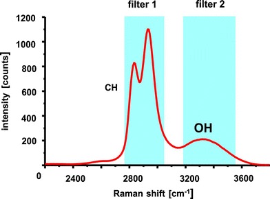
Typical Raman spectrum of ethanol with examples of two narrow band filters
The experimental setup is drafted in Fig. 12. A cuvette of fused silica (type 23, Starna) was used for the calibration measurements. A visualization of the ethanol distribution was done in the mixer displayed in Fig. 2. The measurements presented here were carried out with water and ethanol as two distinct chemical features. The rationale is that they are readily available and safe to handle. Furthermore, ethanol is an organic solvent and hence has an intense characteristic band in the Raman spectrum as shown at approximately 3,000 cm−1 (CH-band). The excitation was done with a pulsed Nd:YAG laser at 532 nm (Brilliant B, Quantel). The intensity of the Raman stray light strongly depends on the excitation wavelength. Due to this strong dependency (I R ∼ λ−4) a laser with a short wavelength should be used in order to obtain intense signals. The use of an UV laser (248 nm) resulted in experimental problems due to significant superimposed fluorescence emissions from the fluids. These problems were circumvented by employing visible light at a wavelength of 532 nm for the excitation.
Fig. 12.
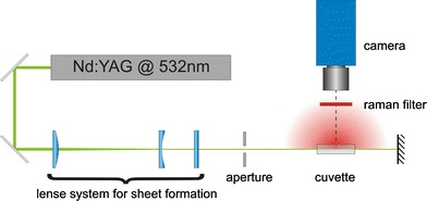
Sketch of the experimental setup for the two dimensional determination of concentration fields by planar Raman scattering
The pulsed, frequency doubled Nd:YAG laser beam is formed to a small light sheet (approximately 800 μm thick and 12 mm high) by a lens system. The light sheet selects a plane in the cuvette that is imaged with an image intensified camera (Flamestar III, LaVision) through the Raman filter (633FS10-25, LOT Oriel). The Raman filter represents the central element for these measurements. It has to be precisely fitted to the Raman spectra of the observed substances and should exhibit a transmission as high as possible. The probability for converting the excitation light to Raman stray light is several orders lower than for fluorescence light. This makes an optimization of the setup with regard to the detected intensities necessary. The transmission of the actual filter is shown in Fig. 13. The figure also shows the Raman spectra of liquid ethanol and water. Especially the CH- and the OH-bands are interesting when a mixture of these fluids should be observed. The bright CH-band of ethanol perfectly fits the range of the filter. Both fluids have an OH-band but the one of water is much brighter. A small amount of light from the OH-band of water is visible via the filter as well. For a mixture of two components the unwanted light can easily be removed by a black-and white-image correction. In this case the black-image would contain the intensities measured of pure water and the white-image is taken from pure ethanol.
Fig. 13.
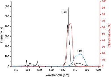
Transmission of the filter (red) and Raman spectra of liquid ethanol (black) and water (blue)
Measurements within the flat micro mixer shown in Fig. 1 have been carried out first. The image acquisition had to be done by integration of several exposures to be able to detect the low intensities. Hence, only stationary flows could be visualized or an averaged view on instationary processes had to be accepted. The lamination mixer shown in Fig. 2 allows to utilize the excitation light much more efficiently than it would be possible with the flat micro mixer. The excitation photons pass the area of interest from the side hence they have to pass an much larger distance within the medium. This leads to a distinctly raised probability to excite Raman photons. Through a calibration, the measured intensity values have to be mapped onto concentration values of the species under consideration. For calibration purposes, ethanol and water have been homogeneously mixed in the cuvette in well defined mass fractions and are subsequently imaged by the Raman system. At first, the cuvette was filled with pure demineralized water. The observation through the Raman filter that selects the fundamental CH-stretching oscillation of the hydrocarbons (approximately 3,000 cm−1) makes sure that almost no light reaches the camera. However, the characteristic OH-oscillation band of water slightly overlaps with the transmission band of the filter in such a way that minor intensities of water are detected, too (Fig. 13). Two images of the pure fluids are needed for a quantitative calibration. A white-image is taken by imaging the cuvette filled with pure ethanol and a black-image by imaging pure water. If the intensity value of pure water is set to zero and the intensity of pure ethanol to one the resulting values represent the concentration of ethanol for all mixture ratios. A measured concentration should correspond to the presetted mass fraction of this mixture. It has to be concerned that the measured Raman intensity is proportional to the number of molecules in the interrogated region. The preparation of several mixture ratios of water and ethanol was done by weighing and the ratio is therefore given as mass fraction. The mass fraction differs from the fraction of the particle numbers because of different specific densities. Hence the mass fractions have to be adapted by consideration of their specific densities. In Fig. 14 the measured concentrations are plotted against the adapted mass ratios. The intensity images were averaged in order that inhomogeneities for example caused by the laser beam profile can be disregarded. For a better comparison, the bisecting line is plotted too, to show a perfect match of both values. The values at zero and one match perfectly thus they were used for the calibration. The measured intensities correspond to the presetted mass fractions very well. This proves the linear dependency and shows that a quantitative measurement is possible by this procedure.
Fig. 14.
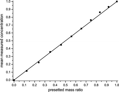
Ethanol concentration measured by planar Raman imaging
The previously described calibration procedure cannot only be employed for integral measurements but also spatially resolved for every single pixel of the image. The time-invariant inhomogeneities of the laser beam profile are taken into account in this case because they appear in the white-image. Errors arise from pulse to pulse fluctuations of the laser intensity and time dependent variations of the laser beam profile which could not be acquired by the calibration that was done before the measurement. These sources of error are known and have not yet been addressed.
A first measurement in a micro channel was carried out with the micro mixer presented in Fig. 2. The experimental setup was not changed apart from the replacement of the cuvette by the mixer. Figure 15 shows a sequence of images acquired during the mixing process in the mixing region. The laser sheet selected a plane cutting through the inlets of ethanol which flows into pure water. The flow rate was adjusted to 500 ml/h per fluid. The exposure time of the images is extremely short because the intensities could be optimized to allow single exposures. Hence the exposure time is given by the laser pulse duration of approximately 6 ns. The acquisition rate that is given by the readout frequency of the camera was about 1 Hz and thus was much slower than necessary to grab the processes time resolved. The intensities were standardized as described above. The distribution of ethanol is clearly visible and some interesting features are recognizable. The intensity values within the ethanol filaments is near one as expected. Between the filaments, ethanol is mixed with water in a lower concentration. In these areas recirculation areas can be found particularly to the right, for example in Fig. 15b or c. The laser sheet runs from the right side to the left and is focused to horizontal lines by means of the different refraction indices of water and ethanol. These horizontal lines of higher intensities are a further source of error which has to be considered for the calculation of concentration values.
Fig. 15.
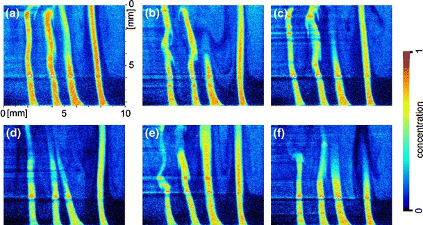
Planar concentration distribution of ethanol in water during an instationary mixing process in the mixing region of the micro mixer shown in Fig. 2
Conclusions
Two dimensional molecular tagging velocimetry was successfully used to determine velocity vector fields in two dimensional micro flows. The evaluation algorithms were extended to address Taylor dispersion. A comparison with the reference measurements of the flow meter showed that the evaluation provided reasonable results which matched the reference very well. The reference measurements showed systematic deviations for higher flow velocities. To draw further conclusions about this deviation and for a comparison with a commonly accepted measurement procedure, μPIV measurements were carried out using the same fluidic system. Again a comparison with the reference measurements gathered by the flow meter was realized. In this case a systematic deviation of 6% could be observed which is assumed to be caused by an error in the calibration values. Thus the deviation observed in the reference comparison of the tagging evaluation might be caused by this error, too. The procedure of planar spontaneous Raman scattering was successfully calibrated on simple model systems. Evaluations of the linear correlation between recorded stray light intensities and preset concentration values resulted in very good accordance. Visualizations of concentration fields of an ethanol flow in water showed the potential of this technique. Due to the fact that the detected intensities could be seriously optimized a single exposure was sufficient. The resulting time resolution of the acquisition process was determined by the duration of the laser pulse of approximately 6 ns. This allows to visualize fast mixture processes in the dimensions of microfluidic devices. In the future a combination of both measurement procedures is planned to gather comprehensive information of microfluidic mixture processes. The combined measurement procedure will support the optimization of mixing processes and the monitoring of specific molecular species in microfluidic devices.
Acknowledgments
The Authors thank the German Research Community (Deutsche Forschungsgemeinschaft-DFG) for funding of the project in the framework of the DFG-program “Imaging techniques for flow analysis” (“Bildgebende Messvervahren für die Strömungsanalyse”, SPP 1147) as well as in the priority program “Mathematical methods for time series analysis and digital image processing”, SPP 1114.
References
- Barron JL, Fleet D, Beauchemin S. Performance of optical flow techniques. Int J Comput Vis. 1994;12(1):43–77. doi: 10.1007/BF01420984. [DOI] [Google Scholar]
- Bazile R, Stepowski D. Measurement of the vaporization dynamics in the development zone of a burning spray by planar laser induced fluorescence and raman scattering. Exp Fluids. 1994;16:171–180. doi: 10.1007/BF00206536. [DOI] [Google Scholar]
- Burns JR, Ramshaw C. The intensification of rapid reactions in multiphase systems using slug flow in capillaries. Lab Chip. 2001;1:10–15. doi: 10.1039/b102818a. [DOI] [PubMed] [Google Scholar]
- Erickson D, Li D. Integrated microfluidic devices. Anal Chim Acta. 2004;507:11–26. doi: 10.1016/j.aca.2003.09.019. [DOI] [Google Scholar]
- Garbe CS (2006) Measuring and modeling fluid dynamic processesusing digital image sequence analysis. Habil. Ruprecht-Karls-Universität, Heidelberg
- Garbe CS, Spies H, Jähne B. Estimation of surface flow and net heat flux from infrared image sequences. J Math Imaging Vis. 2003;19:159–174. doi: 10.1023/A:1026233919766. [DOI] [Google Scholar]
- Garbe CS, Roetmann K, Jähne B (2006) An optical flow based technique for the non-invasive measurement of microfluidic flows. In: 12th International symposium on flow visualization. Göttingen, Germany, pp 1–10
- Garbe CS, Degreif K, Jähne B (2007a) Estimating the viscous shear stress at the water surface from active thermography. In: Transport at the air sea interface—measurements, models and parametrizations. Springer, Heidelberg, pp 223–239
- Garbe CS, Roetmann K, Beushausen V, Jähne B (2007b) An optical flow mtv based technique for measuring microfluidic flow in the presence of diffusion and taylor dispersion. Exp Fluids (submitted)
- Gee KR, Weinberg ES, Kozlowski DJ. Caged q-rhodamine dextran: a new photoactivated fluorescent tracer. Bioorg Med Chem Lett. 2001;11(16):2181–2183. doi: 10.1016/S0960-894X(01)00421-8. [DOI] [PubMed] [Google Scholar]
- Gendrich CP, Koochesfahani MM, Nocera DG. Molecular tagging velocimetry and other novel applications of a new phosphorescent supramolecule. Exp Fluids. 1997;23:361–372. doi: 10.1007/s003480050123. [DOI] [Google Scholar]
- Haußecker H, Fleet D. Computing optical flow with physical models of brightness variation. IEEE Trans Pattern Anal Mach Intell. 2001;23(6):661–673. doi: 10.1109/34.927465. [DOI] [Google Scholar]
- Inaba S, Sato Y, Hishida K, Maeda M (2001) Flow measurements in microspace using sub-micron fluorescent particles—an effect of brownian motion on velocity detection. In: 4th International symposium on particle image velocimetry
- Jähne B. Digitale Bildverarbeitung. 6. Heidelberg: Springer; 2005. [Google Scholar]
- Koochesfahani MM, Nocera DG (2001) Molecular tagging velocimetry maps fluid flows. Laser Focus World, Los Gartos, pp 103–108
- Krüger S, Grünefeld G, Arndt S, Hentschel W (2000) Planar velocity measurements of the gas and liquid phase in dense sprays by flow tagging. In: 10th International symposium on applications of laser techniques to fluid mechanics
- Lai S, Wang S, Luo J, Lee LJ, Yang ST, Madou MJ. Design of a compact disk-like microfluidic platform for enzyme-linked immunosorbent assay. Anal Chem. 2004;76(7):1832–1837. doi: 10.1021/ac0348322. [DOI] [PubMed] [Google Scholar]
- Lee M, Lee JP, Rhee H, Choo J, Chai YG, Lee EK. Applicability of laser-induced raman microscopy for in situ monitoring of imine formation in a glass microfluidic chip. J Raman Spectroscopy. 2003;34:737–742. doi: 10.1002/jrs.1038. [DOI] [Google Scholar]
- Lempert WR, Harris SR. Flow tagging velocimetry using caged dye photo-activated fluorophores. Meas Sci Technol. 2000;11:1251–1258. doi: 10.1088/0957-0233/11/9/302. [DOI] [Google Scholar]
- Lempert WR, Magee K, Ronney P, Gee KR, Haugland RP. Flow tagging velocimetry in incompressible flow using photo-activated nonintrusive tracking of molecular motion (phantomm) Exp Fluids. 1995;18:249–257. doi: 10.1007/BF00195095. [DOI] [Google Scholar]
- Leung SA, Winkle RF, Wootton RCR, deMello AJ. A method for rapid reaction optimisation in continuous-flow microfluidic reactors using online raman spectroscopic detection. Analyst. 2004;130:46–51. doi: 10.1039/b412069h. [DOI] [PubMed] [Google Scholar]
- Malarski A, Egermann J, Zehnder J, Leipertz A. Simultaneous application of single-shot ramanography and particle image velocimetry. Opt Lett. 2006;31:1005–1007. doi: 10.1364/OL.31.001005. [DOI] [PubMed] [Google Scholar]
- Maynes D, Webb AR. Velocity profile characterization in sub-millimeter diameter tubes using molecular tagging velocimetry. Exp Fluids. 2002;32:3–15. doi: 10.1007/s003480200001. [DOI] [Google Scholar]
- Meinhart CD, Wereley ST, Gray MHB. Volume illumination for two-dimensional particle image velocimetry. Meas Sci Technol . 2000;11:809–814. doi: 10.1088/0957-0233/11/6/326. [DOI] [Google Scholar]
- Mogensen KB, Klank H, Kutter JP. Recentdevelopments in detection for microfluidic systems. Electrophoresis. 2004;25:3498–3512. doi: 10.1002/elps.200406108. [DOI] [PubMed] [Google Scholar]
- Mosier BP, Molho JI, Santiago JG. Photobleached-fluorescence imaging of microflows. Exp Fluids. 2002;33:545–554. [Google Scholar]
- Nguyen NT, Wereley ST. Fundamentals and applications of microfluidics. Norwood: Artech House; 2002. [Google Scholar]
- Nguyen NT, Wu Z. Micromixers—a review. J Micromech Microeng. 2005;15:R1–R16. doi: 10.1088/0960-1317/15/2/R01. [DOI] [Google Scholar]
- Paege BM, Emrich CA, Wedemayer GJ, Scherer JR, Mathies RA. High throughput dna sequencing with a microfabricated 96-lane capillary array electrophoresis bioprocessor. PNAS. 2001;99:574–579. doi: 10.1073/pnas.012608699. [DOI] [PMC free article] [PubMed] [Google Scholar]
- Paul PH, Garguilo MG, Rakestraw DJ. Imaging of pressure- and electrokinetically driven flows through open capillaries. Anal Chem. 1998;70:2459–2467. doi: 10.1021/ac9709662. [DOI] [PubMed] [Google Scholar]
- Roetmann K, Garbe C, Beushausen V (2005) 2d-molecular tagging velocimetry zur analyse mikrofluidischer strömungen. In: Tagungsband Lasermethoden in der Strömungsmesstechnik, pp 26/1–26/10
- Roetmann K, Garbe C, Schmunk W, Beushausen V (2006a) Micro-flow analysis by molecular tagging velocimetry and planar raman-scattering. In: 12th International symposium on flow visualization [DOI] [PMC free article] [PubMed]
- Roetmann K, Schmunk W, Garbe C, Beushausen V (2006b) Analyse mikrofluidischer strömungen mit molecular tagging velocimetry und planarer ramanstreuung. In: Tagungsband Lasermethoden in der Strömungsmesstechnik, pp 31/1–31/8
- Santiago JG, Wereley ST, Meinhart CD, Beebe DJ, Adrian RJ. A particle image velocimetry system for microfluidics. Exp Fluids. 1998;25:316–319. doi: 10.1007/s003480050235. [DOI] [Google Scholar]
- Scharr H (2004) Optimal filters for extended optical flow. In: Complex motion IWCM 2004, Lecture Notes in Computer Science. Springer, Heidelberg
- Shinohara K, Sugii Y, Aota A, Hibara A, Tokeshi M, Kitamori T, Okamoto K. High-speed micro-piv measurements of transient flowin microfluidic devices. Meas Sci Technol. 2004;15:1965–1970. doi: 10.1088/0957-0233/15/10/003. [DOI] [Google Scholar]
- Sinton D. Microscale flow visualization. Microfluid Nanofluid. 2004;1:2–21. doi: 10.1007/s10404-004-0009-4. [DOI] [Google Scholar]
- Srinivasan V, Pamula VK, Fair RB. An integrated digital microfluidic lab-on-a-chip for clinical diagnostics on human physiological fluids. Lab Chip. 2004;4:310–315. doi: 10.1039/b403341h. [DOI] [PubMed] [Google Scholar]
- Stier B, Koochesfahani MM. Molecular tagging velocimetry (mtv) measurements in gas phase flows. Exp Fluids. 1999;26:297–304. doi: 10.1007/s003480050292. [DOI] [Google Scholar]
- Viskari PJ, Landers JP. Unconventional detection methods for microfluidic devices. Electrophoresis. 2006;27:1797–1810. doi: 10.1002/elps.200500565. [DOI] [PubMed] [Google Scholar]
- Wang J. From dna biosensors to gene chips. Nucleic Acids Res. 2000;28(16):3011–3016. doi: 10.1093/nar/28.16.3011. [DOI] [PMC free article] [PubMed] [Google Scholar]
- Wood BR, Langford SJ, Cooke BM, Glenister FK, Lim J, McNaughton D. Raman imaging of hemozoin within the food vacuole of plasmodium falciparum trophozoites. FEBS Lett. 2003;554:247–252. doi: 10.1016/S0014-5793(03)00975-X. [DOI] [PubMed] [Google Scholar]
- Zhou X, Liu D, Zhong R, Dai Z, Wu H, Wang H, DU Y, Xia Z, Zhang L, Mei X, Lin B. Determination of sars-coronavirus by a microfluidic chip system. Electrophoresis. 2004;25(17):3032–3039. doi: 10.1002/elps.200305966. [DOI] [PMC free article] [PubMed] [Google Scholar]


