Abstract
Background
Despite the development of minimally invasive techniques for pelvic fractures, performing minimally invasive surgery for Tile C3 pelvic fractures remains challenging. Thus, we propose use of anterior ring internal fixation combined with sacroiliac screw fixation for Tile C3 pelvic fractures.
Material/Methods
A normal pelvic finite element model (model 1) was established. Two-screw, three-screw, and four-screw anterior ring internal fixators and plate combined with sacroiliac screw Tile C3 pelvic fracture models (models 2, 3, 4, and 5, respectively) were also established. A vertical load of 600 N was applied on S1. The distribution of displacement and stress in the standing and sitting positions was compared.
Results
Models 2, 3, 4, and 5 can provide effective fixation. Compared with model 1, in the erect position, the maximum displacement of models 2, 3, 4, and 5 increased by 66.51%, 65.36%, 35.16%, and 35.47% and the maximum stress increased by 201.78%, 130.65%, 100.82%, and 99.03%, respectively. Compared with model 1, in sitting position, the maximum displacement of models 2, 3, 4, and 5 increased by 9.1%, 11.04%, 5.57%, and 8.59% and the maximum stress increased by 157.73%, 118.02%, 98.32%, and 93.16%, respectively.
Conclusions
Anterior ring internal fixators combined with sacroiliac screws can effectively fix Tile C3 pelvic fractures.
MeSH Keywords: Biomechanics, Finite Element Method, Internal Fixation System, Pelvic Fracture
Background
With the development of minimally invasive techniques, pelvic fractures may eventually be treated using such approaches. Closed-reduction sacroiliac screw fixation for vertically unstable posterior rings has become a common surgical method. The treatment of anterior ring fractures with subcutaneous screw-rod internal fixation has been reported, and good results have been achieved [1]; this is known as subcutaneous internal fixation [2,3] or the INFIX technique [4–6]. Tile C3 pelvic fractures, which are the most serious pelvic fractures, are characterized by severely unstable anterior and posterior pelvic rings, high-energy injury, and concomitant organ injury. Early routine pelvic surgery often cannot be performed due to various reasons, and old fractures can easily form. Thus, there are many difficulties in treating pelvic fractures in the later stage. A stable pelvis can be obtained with early minimally invasive treatment. Thus, surgical conditions for concomitant organ injury are established. Early accurate restoration and fixation can prevent old fractures and reduce complications. Minimally invasive treatment of Tile C3 pelvic fractures has always been one of the major challenges for orthopedists. We propose a minimally invasive treatment of Tile C3 fractures using anterior ring fixators combined with sacroiliac screws
Here, we assessed the biomechanical characteristics of ring subcutaneous internal fixators and plates combined with sacroiliac screws and compared them using the finite element method.
Material and Methods
Establishment of the finite element model
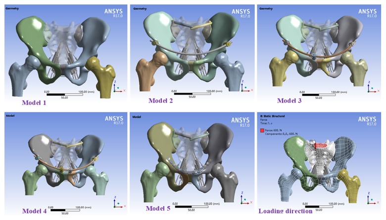
A 35-year-old healthy male volunteer (170 cm in height, 70 kg in weight) was selected. Pelvic scanning (0.5 mm in each layer) was performed using 128-slice computed tomography (CT) (Siemens, Germany). Obtained CT imaging data were used as the original data for mechanical analysis [7,8]. The pelvic model was established by importing the data into Mimics 16.0 (Materialise, Belgium). Geomagic Studio 2013 (Geomagic, USA) was used for smooth optimization and curved surface accuracy. SolidWorks 2017 (Dassault Systemes S.A., USA) was employed to establish cortical bone; cancellous bone; anterior ring internal fixator, plate, and screw; and Tile C3 pelvic fracture models (bilateral dislocation of the sacroiliac joint and bilateral fracture of the superior and inferior rami of the pubis) [9]. A normal pelvic model (model 1); two-screw (model 2), three-screw (model 3), and four-screw (model 4) internal fixators combined with sacroiliac screw models; and plate combined with sacroiliac screw model (model 5) were established. A geometric model was introduced into ANSYS17.0 (ANSYS, USA). Further, a static structural analysis type was established. In the geometry model, pelvis, ligament, internal fixation, and other models were provided relevant material parameters [10]. Contact types between the models were defined. Contact between fracture surfaces and between screws, plates, and bones was frictional and nonlinear, respectively. The other contact types were bound; the relationship was fixation. Mesh generation was performed on the model, and the type and size were controlled. Thus, a complete model was established (Figure 1). This study was approved by the Ethics Committee of the Third Affiliated Hospital, Southern Medical University.
Figure 1.
Model diagram and load direction.
Analysis of model displacement and stress
Boundary conditions and load were set in ANSYS17.0. The lower surface of the femur in the standing position was fixed. The 6 degrees of freedom of the bilateral acetabulum were constrained. Thereafter, the tubercle in the standing position was fixed. The 6 degrees of freedom of the bilateral ischial tuberosity were constrained [11,12]. A uniformly distributed load (load speed, 10 N/s) of 600 N was applied vertically downward on the upper surface of S1 [13] to calculate model displacement and stress.
Results
Displacement analysis
Displacement analysis in standing position
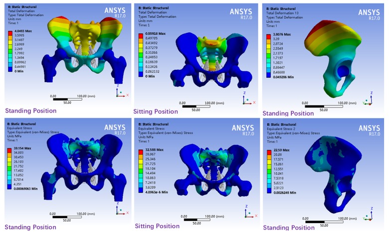
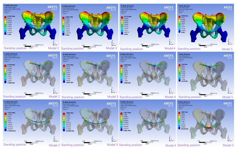
In model 1, displacement distribution was bilaterally symmetrical with the median sacral crest as the center. The displacement distribution in the sacrum decreased gradually from top to bottom. The displacement distribution in the ilium centered on the acetabular fossa and gradually decreased from the posterosuperior ilium and the pubic symphysis in wave form. The maximum displacement was located in the posterosuperior part of the iliac wing (Figure 2). The displacement distribution of each fixation model was similar to that of the normal pelvic model. The maximum displacement was located in the posterosuperior part of the iliac wing and S1 (Figure 3). Compared with that in model 1, the maximum overall displacement in models 2, 3, 4, and 5 increased by 66.51%, 65.36%, 35.16%, and 35.47%, respectively (Table 1). Compared with that in model 1, the maximum horizontal displacement in models 2, 3, 4, and 5 increased by 84.76%, 104.22%, 83.47%, and 63.99%, respectively. The corresponding maximum vertical displacement increased by 67.92%, 51.11%, 34.81%, and 52.35%, respectively.
Figure 2.
Displacement and stress distribution in model 1.
Figure 3.
Displacement distribution of fixed models in standing position.
Table 1.
Maximum displacement in the standing position (mm).
| Model 1 | Model 2 | Model 3 | Model 4 | Model 5 | |
|---|---|---|---|---|---|
| Overall | 4.0483 | 6.7407 | 6.6941 | 5.4718 | 5.48330 |
| Horizontal | −0.18596 | 0.34359 | 0.37976 | 0.34118 | 0.30496 |
| Vertical | −2.4934 | −4.1869 | −4.1671 | −3.3613 | −3.7986 |
| Sacroiliac screw | 4.1746 | 3.7677 | 3.3608 | 5.24400 | |
| Internal fixator | 1.8797 | 1.3901 | 1.3557 | 1.9831 |
The displacement distribution of the sacroiliac screw in each model (Figure 3) was bilaterally symmetrical and decreased gradually from outside to inside in wave form. Maximum displacement was seen on the screw cap and models 2, 3, and 4 were reduced by 20.39%, 28.15%, and 35.91%, respectively, compared with model 5 (Table 1). The displacement distribution of the fixed rod in models 2–4 was consistent and decreased gradually from the 2 sides to the middle. The maximum displacement was located in the screw-rod binding region. Compared with that in model 5, the maximum displacement of models 2, 3 and 4 decreased by 5.21%, 29.9%, and 31.64%, respectively.
All models could provide enough stability in the standing position. The overall displacement was sorted as follows: model 4< model 5< model 3< model 2, and model 2 is close to model 3 displacement; horizontal displacement: model 5< model 4< model 2< model 3; vertical displacement: model 4< model 5< model 3< model 2; displacement of the sacroiliac screw: model 4< model 3< model 2< model 5; and displacement of the anterior ring internal fixator: model 4< model 3< model 2< model 5.
Displacement analysis in the sitting position
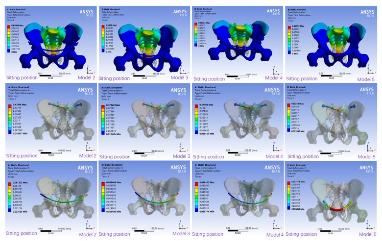
The overall displacement in each model was bilaterally symmetrical and was mainly located in the sacrum (Figure 4). The overall displacement in model 1 was bilaterally symmetrical with the median sacral crest as the center and decreased gradually from the proximal and distal ends to S2 (Figure 2). The maximum displacement was located in the anterosuperior part of S1. Compare to model 1, the displacement distribution of models 2, 3, 4, and 5 increased by 9.1%, 11.04%, 5.57%, and 8.59%, respectively (Table 2). The maximum horizontal displacement was located in the posterosuperior part of the ilium and increased by 213.55%, 209.47%, 204.93%, and 205.32% in models 2, 3, 4, and 5, respectively. The maximum vertical displacement was located in the sacrum of the sacroiliac joint region and increased by 111.73%, 112.5%, 107.28%, and 68.14% in models 2, 3, 4, and 5, respectively, compared with model 1.
Figure 4.
Displacement distribution of fixed models in sitting position.
Table 2.
Maximum displacement in the sitting position (mm).
| Model 1 | Model 2 | Model 3 | Model 4 | Model 5 | |
|---|---|---|---|---|---|
| Overall | 0.55918 | 0.61004 | 0.62090 | 0.59034 | 0.60719 |
| Horizontal | 0.038042 | 0.11928 | 0.11773 | 0.116 | 0.11615 |
| Vertical | −0.040593 | −0.085947 | −0.086258 | −0.08414 | −0.068254 |
| Sacroiliac screw | 0.47856 | 0.47822 | 0.47102 | 0.38218 | |
| Internal fixator | 0.061303 | 0.062464 | 0.056103 | 0.037779 |
The displacement distribution of the sacroiliac screw in each fixation model increased gradually from outside to inside (Figure 4). The maximum displacement was located in the screw tip. Compared with that in model 5, the maximum displacement in models 2, 3, and 4 changed by 25.22%, 25.13%, and 23.25%, respectively (Table 2). The displacement distribution of the anterior ring plate decreased from the center to the 2 sides. The maximum displacement was located in the middle region of the plate. The displacement distribution of the fixation rod in models 2–4 was similar. Compared with that in model 5, the displacement in models 2, 3, and 4 increased by 62.27%, 65.34%, and 48.5%, respectively.
All models provided adequate stability in the sitting position. Overall displacement were sorted as follows: model 4< model 5< model 2< model 3; horizontal displacement were sorted as follows: model 4< model 5< model 3< model 2; vertical displacement: model 5< model 4< model 3< model 2; displacement of the sacroiliac screw and displacement of the anterior ring internal fixator: model 5< model 4< model 3< model 2.
Stress analysis
Stress distribution analysis in the standing position
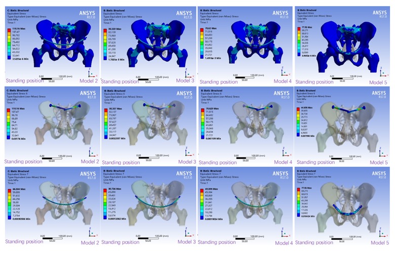
Stress distribution in the normal pelvic model was bilaterally symmetrical and was mainly located in the upper region of the sacrum and sacroiliac joint region (Figure 2). Stress distribution in each fixation model was consistent with that in the normal pelvic model. The maximum stress in model 5 was mainly located in S1 and the anterior ring plate. However, stress distribution in models 2–4 was more consistent with that in the normal pelvic model. The maximum stress was mainly located in S1, S2, and the internal fixator (Figure 5). Compared with that in model 1, the maximum stress in models 2, 3, 4, and 5 increased by 201.78%, 130.65%, 100.82%, and 99.03%, respectively (Table 3).
Figure 5.
Stress distribution in the fixed models in standing position (MPa).
Table 3.
Maximum stress in the models (MPa).
| Model 1 | Model 2 | Model 3 | Model 4 | Model 5 | |
|---|---|---|---|---|---|
| Standing position | 39.154 | 118.16 | 90.309 | 78.63 | 77.93 |
| Sitting position | 32.588 | 83.99 | 71.049 | 64.628 | 62.952 |
The stress distribution of the sacroiliac screw in each fixation model was consistent and bilaterally symmetrical. Stress distribution decreased gradually from the sacroiliac joint region to the 2 sides (Figure 5). Compared with that in model 5, the maximum stress in models 2, 3, and 4 increased by 164.6%, 102.23%, and 76.08%, respectively (Table 4). The stress of the plate in model 5 was irregularly distributed. The stress distribution of the internal fixation rods in models 2–4 was consistent. Compared with that in model 5, the stress in models 2, 3, and 4 decreased by 14.82%, 34.9%, and 35.97%, respectively.
Table 4.
Maximum stress of the internal fixators in the models (MPa).
| Model 2 | Model 3 | Model 4 | Model 5 | |
|---|---|---|---|---|
| Sacroiliac screw in standing position | 118.16 | 90.307 | 78.629 | 44.656 |
| Anterior ring fixation in standing position | 66.384 | 50.736 | 49.898 | 77.93 |
| Sacroiliac screw in sitting position | 83.99 | 71.049 | 64.628 | 62.952 |
| Anterior ring fixation in sitting position | 3.035 | 4.0898 | 4.2333 | 16.102 |
The maximum stress in all fixed models was significantly higher than that in the normal model. The maximum stress was sorted as follows: model 5< model 4< model 3< model 2; maximum stress of the sacroiliac screws: model 5< model 4< model 3< model 2; and maximum stress of the anterior ring internal fixators: model 4< model 3< model 2< model 5.
Stress distribution analysis in sitting position
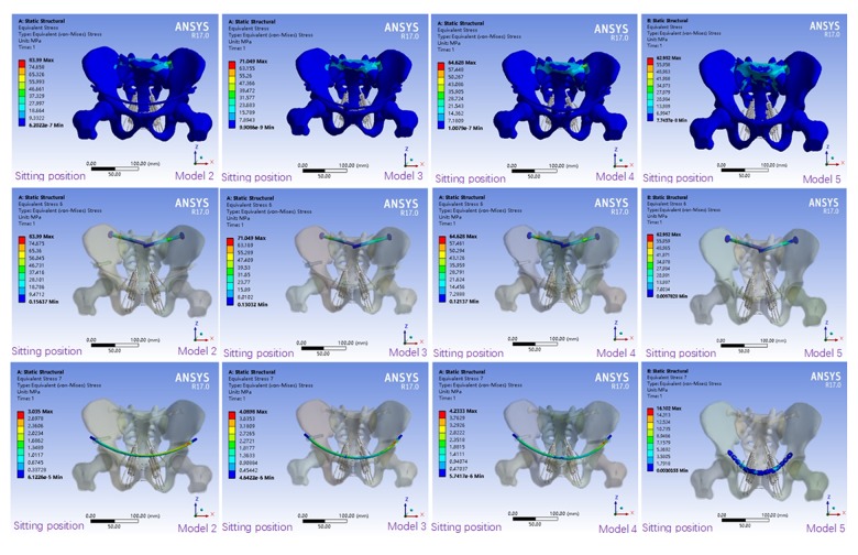
Stress distribution in model 1 was mainly focused on S1, S2, and the corresponding sacral wing (Figure 2). Stress in the ilium, ischium, and pubis was uniformly distributed. The stress distribution was similar to that in model 1. Compared with that in model 1, the maximum stress distribution in model 5 significantly decreased and was mainly located in S1 and the partial ilium around the sacroiliac joint. Stress distribution in models 2, 3, and 4 was similar to that in model 1. The maximum stress was distributed on S1, S2, and the corresponding sacral swing and ilium (Figure 6). Compared with that in model 1, the maximum stress in models 2, 3, 4, and 5 increased by 157.73%, 118.02%, 98.32%, and 93.16%, respectively (Table 3).
Figure 6.
Stress distribution in the fixed models in sitting position (MPa).
The stress distribution of the sacroiliac screw in each fixation model was consistent and decreased gradually from the sacroiliac joint region to the 2 sides. The maximum stress was located in the sacroiliac joint region (Figure 6). Compared with that in model 5, the maximum stress in models 2, 3, and 4 increased by 33.42%, 12.86%, and 2.66%, respectively (Table 4). The stress distribution of the anterior ring plate in model 5 was uniform. The stress distribution of the anterior ring fixator in models 2–4 was consistent. Compared with that in model 2, the maximum stress in models 3, 4, and 5 increased by 15.8%, 17.95%, and 528.86%, respectively.
The maximum stress of the pelvis in models 2, 3, and 4 was significantly smaller than that in model 5. The maximum stress was sorted as follows: model 5< model 4< model 3< model 2; maximum stress of the sacroiliac screw: model 5< model 4< model 3< model 2; and maximum stress of the anterior ring internal fixator: model 2< model 3< model 4< model 5.
Discussion
Pelvic stability depends on the anterior and posterior pelvic rings. The anterior ring provides 30% of the stability and the posterior ring provides 70% of the stability [14]. Tile C3 fractures are the most serious and unstable pelvic fractures; the anterior and posterior rings are unstable and need to be fixed. For posterior ring injury, percutaneous iliac screw fixation has been widely used in clinical practice. Studies have shown that sacral screw fixation of unstable pelvic fractures is a convenient technique for achieving good stability [15,16]. The present study found that the posterior annulus was fixed with a diameter of 7.3 mm and the posterior rings in each model were well stabilized. Letournel [17] first applied sacroiliac screw fixation for posterior ring injuries. Currently, the technique is widely used in clinical practice. Osterhoff et al. used sacroiliac screws for fixation of unstable pelvic fractures.
The method is considered to be convenient [15, 18]. Good stability can be obtained by using sacroiliac screws for fixation of the posterior pelvic ring. Anterior ring fractures are traditionally fixed with plate or anterior channel screws. In 2009, Kuttner et al. [19] used the needle rod system to subcutaneously fix the anterior pelvic ring of 19 patients with unstable pelvic fractures and achieved good results. This system is known as anterior subcutaneous pelvic internal fixation. In 2011, Vaidya et al. [4,20] used the same method to treat unstable pelvic fractures and also achieved good results. The above-mentioned method is referred to as the INFIX technology.
Gradually, the technique has become popularized and is used in clinical practice. Many researchers have studied the biomechanics of anterior ring internal fixators [14,21–23]. In the study by Vigdorchik et al. [24], the posterior sacroiliac joint was fixed using sacroiliac screws and the anterior pelvic ring was fixed using the INFIX technology and acetabular external fixators. Comparison of the stability of these 2 techniques showed that the stability of INFIX was almost twice that of acetabular external fixators. Osterhoff et al. reported that INFIX has better stability in fixation of the pubic symphysis and sacroiliac joint than with external fixators [25]. Vigdorchik et al. reported that INFIX has better biomechanical stability in the treatment of vertical unstable pelvic fractures than external fixators and plates [24].
Here, we found that the anterior ring internal fixators combined with sacroiliac screws fixation model achieved good biomechanical stability in both the anterior and posterior rings. A 2016 study [26] found that anterior ring internal fixation is a more minimally invasive and effective method for the treatment of anterior ring fractures and that it has a short learning curve. Currently, internal fixation is mainly used for the treatment of Tile B pelvic fractures. The effect of internal fixation on Tile C pelvic fractures has not been systematically studied. Some researchers preliminarily used internal fixation for Tile C1 pelvic fractures [27].
The traditional pelvic specimen method for mechanical tests can simulate the displacement and injury of body structures, but the distribution of pelvic stress cannot be detected. It can easily be affected by many factors, such as specimen source and individual differences [28]. Finite element method software has rapidly developed in the last 20 years. The finite element method has been widely used in biomechanical studies of the pelvis [29–31]. In the present study, Tile C3 pelvic fracture models were established using the finite element method, and the stability of pelvic fractures with different fixation methods was analyzed and compared. The distribution of displacement and stress in the normal pelvic model was wave-like, which is similar to the findings in the literature [30,32]. In 2013, Lee et al. [31] reported that equivalent stress in the cortical bone was 13.5–25.7 MPa under a 500-N load and the maximum equivalent stresses in the normal pelvic cortical bone in the standing and sitting positions were 16.09 MPa and 13.753 MPa, respectively. The above-mentioned results are within the reported stress range. In 2011, Hao et al. reported that under a complete pelvic finite element model, the maximum stress of tibia in sacroiliac joints was 15 MPa at 550 N vertical load [33]. In 2014, the pelvic finite element model was established, and the maximum stress of the tibia under the vertical load of 500N was 16.5 MPa [34]. In our study, the maximum stress was 17.402 MPa. The pelvic displacement and stress distribution of the normal pelvis model under 600N load are shown in Figure 2. The displacement distribution is wavy. Phillips et al. [35], Fan et al. [36], and Lei et al. [37] reported consistent results. Fan et al. showed maximum displacement of the ilium of 2.59 mm and a maximum stress of 25 MPa in normal pelvic model. Lei et al. showed a maximum displacement of the ilium of 2.86 mm and a maximum stress of 25 MPa in the normal pelvic model. We found that the maximum displacement of the ilium in the normal model was 3.8067 mm and the maximum stress was 22.59 MPa. These differences of the displacement and stress of the model may be due to load, boundary conditions, and the nature of bone and soft tissue (such as neglecting interarticular cartilage, interarticular ligament, and femur) [34]. The results of the present study are basically consistent with the above findings. In summary, the evidence indicates that the pelvic model established is effective.
We found that the distribution of displacement and stress in each fixation pelvic model was similar to that in the normal pelvic model. The results showed that Tile C3 pelvic fractures can be effectively fixed in all fixation models. There were no obvious fractures, re-fractures, dislocations, internal fixation fractures, or obvious deformations in the fixed models. Clinically, it is generally considered that the fracture fixation fails when the displacement between the fracture surfaces is 2 cm [38]. Dujardin et al. also showed posterior pelvic ring displacement <1 cm indicated better prognosis [39,40]. Compared with the normal model, the maximum displacement in erect position of the pelvis increased by 1.4235–2.6924mm, and in seated position increased by 0.03116–0.06172 mm. The results of this study show that in erect position, model 4 has the smallest displacement in the whole, vertical direction, and internal fixation, and model 5 has the smallest horizontal displacement. In seated position, model 4 has the smallest overall, horizontal, and vertical displacement, while model 5 has the smallest internal displacement. The displacements of model 4 and model 5 are close, the stability of model 4 is higher, and the stability of model 5 is close to that of model 4. Because of the stress concentration after the internal fixation of the fracture, the maximum stress of the pelvis is significantly higher than that of the normal model, regardless of standing or sitting position. The maximum stress of model 5 is the smallest, and the maximum stress of model 4 is close to model 5. The maximum stress of the ilium in seated position of model 5 is the smallest, model 4 is increased by 33.975 MPa compared with model 5, the maximum stress of the front ring of model 5 is the largest, and model 4 is increased by 28.023 MPa, the maximum stress model of the ilium in seated position is the smallest, and model 4 is close to model 5. The maximum stress models of the front and front rings are close to 2, 3, and 4, and model 5 increased by 11.78678 MPa compared to model 4. The stress distribution of model 4 in the front ring is better than that of the model 5, while the stress distribution of the screw in model 5 is better than that of the model 4. Thus, in terms of stress distribution, models 4 and 5 are better than models 2 and 3, and model 4 is similar to model 5.
At present, there is no relevant literature on whether the anterior ring stent system increases the pubic region fixation screw to provide better stability. In the present study, we established a 3-nail stent system model and a 4-nail stent system model. We found that the overall displacement of model 3 was slightly greater than with model 2 in seated position. The fixation screw was added to the pubic area due to the asymmetry of the front ring fixing screws of the 3-nail bracket system, the seat level, the internal fixation shift, the station displacement, the maximum stress of the station and the seat, with model 2> model 3> model 4. As the front ring stent fixation screw increases, the biomechanical properties of the fixed model gradually increase.
Conclusions
Anterior ring internal fixators combined with sacroiliac screws can effectively fix Tile C3 pelvic fractures, and its biomechanical properties gradually increase with the increase of fixation screws.
Limitations and further studies
The biomechanical characteristics of pelvic injuries can be simulated using the finite element method. Thus, a theoretical basis was provided for the selection of treatment protocols for pelvic fractures. However, only the main ligament was established as the pelvic ligament, and the other ligaments were not considered. Contact between the joints and between bone tissues and internal fixators was set to be an ideal state. Moreover, the parameters of the bone tissue, ligament tissue, internal fixation material, and biological material were assumed to be homogeneous and continuous. All isotropic settings were ideal. Thus, there is difference between the results and the actual physiological state; therefore, the experimental results will be somewhat different from actual clinical conditions [41,42]. To reduce this difference, a normal pelvic model was established. However, the results may still be different from actual outcomes. Thus, biomechanical experimental results of solid specimens need to be validated.
Footnotes
Source of support: Departmental sources
Conflict of interests
None.
References
- 1.Wang ZH, Bo-Yong HE, Zeng MC, et al. Anterior subcutaneous fixation with screw-rod internal fixator for the treatment of unstable anterior pelvic ring fractures. Journal of Traumatic Surgery. 2016;4:10–13. [Google Scholar]
- 2.Cole PA, Gauger EM, Anavian J, et al. Anterior pelvic external fixator versus subcutaneous internal fixator in the treatment of anterior ring pelvic fractures. J Orthop Trauma. 2012;26:269–77. doi: 10.1097/BOT.0b013e3182410577. [DOI] [PubMed] [Google Scholar]
- 3.Hiesterman TG, Hill BW, Cole PA. Surgical technique: A percutaneous method of subcutaneous fixation for the anterior pelvic ring: the pelvic bridge. Clin Orthop Relat Res. 2012;470:2116–23. doi: 10.1007/s11999-012-2341-4. [DOI] [PMC free article] [PubMed] [Google Scholar]
- 4.Vaidya R, Colen R, Vigdorchik J, et al. Treatment of unstable pelvic ring injuries with an internal anterior fixator and posterior fixation: Initial clinical series. J Orthop Trauma. 2012;26:1–8. doi: 10.1097/BOT.0b013e318233b8a7. [DOI] [PubMed] [Google Scholar]
- 5.Gardner MJ, Mehta S, Mirza A, Ricci WM. Anterior pelvic reduction and fixation using a subcutaneous internal fixator. J Orthop Trauma. 2012;26:314–21. doi: 10.1097/BOT.0b013e318220bb22. [DOI] [PubMed] [Google Scholar]
- 6.Scheyerer MJ, Zimmermann SM, Osterhoff G, et al. Anterior subcutaneous internal fixation for treatment of unstable pelvic fractures. BMC Res Notes. 2014;7:133. doi: 10.1186/1756-0500-7-133. [DOI] [PMC free article] [PubMed] [Google Scholar]
- 7.Xi-Ming L, Chang-Wu P, Guo-Dong W, et al. Finite element analysis of the stability of combined plate internal fixation in posterior wall fractures of acetabulum. Int J Clin Exp Med. 2015;8(8):13393–97. [PMC free article] [PubMed] [Google Scholar]
- 8.Yildirim AO, Alemdaroglu KB, Yuksel HY, et al. Finite element analysis of the stability of transverse acetabular fractures in standing and sitting positions by different fixation options. Injury. 2015;46:S29–35. doi: 10.1016/j.injury.2015.05.029. [DOI] [PubMed] [Google Scholar]
- 9.Tao W, Wei C, Xu L, et al. Biomechanical comparison of three types of internal fixation in a type C zone II pelvic fracture model. Int J Clin Exp Med. 2015;8(2):1853–61. [PMC free article] [PubMed] [Google Scholar]
- 10.Anderson AE, Peters CL, Tuttle BD, Weiss JA. Subject-specific finite element model of the pelvis: Development, validation and sensitivity studies. J Biomech Eng. 2005;127:364–73. doi: 10.1115/1.1894148. [DOI] [PubMed] [Google Scholar]
- 11.Hu P, Wu T, Wang HZ, et al. Influence of different boundary conditions in finite element analysis on pelvic biomechanical load transmission. Orthop Surg. 2017;9(1):115–22. doi: 10.1111/os.12315. [DOI] [PMC free article] [PubMed] [Google Scholar]
- 12.Watson PJ, Dostanpor A, Fagan MJ, Dobson CA. The effect of boundary constraints on finite element modelling of the human pelvis. Med Eng Phys. 2017;43:48–57. doi: 10.1016/j.medengphy.2017.02.001. [DOI] [PubMed] [Google Scholar]
- 13.Jazini E, Klocke N, Tannous O, et al. Does lumbopelvic fixation add stability? A cadaveric biomechanical analysis of an unstable pelvic fracture model. J Orthop Trauma. 2017;31(1):37–46. doi: 10.1097/BOT.0000000000000703. [DOI] [PubMed] [Google Scholar]
- 14.Bi C, Wang Q, Nagelli C, et al. Treatment of unstable posterior pelvic ring fracture with pedicle screw-rod fixator versus locking compression plate: A comparative study. Med Sci Monit. 2016;22:3764–70. doi: 10.12659/MSM.900673. [DOI] [PMC free article] [PubMed] [Google Scholar]
- 15.Giráldezsánchez MA, Lázarogonzálvez Á, Martínezreina J, et al. Percutaneous iliosacral fixation in external rotational pelvic fractures. A biomechanical analysis. Injury. 2015;46:327–32. doi: 10.1016/j.injury.2014.10.058. [DOI] [PubMed] [Google Scholar]
- 16.Bousbaa H, Ouahidi M, Louaste J, et al. Percutaneous iliosacral screw fixation in unstable pelvic fractures. Pan Afr Med J. 2017;27:244. doi: 10.11604/pamj.2017.27.244.11506. [DOI] [PMC free article] [PubMed] [Google Scholar]
- 17.Letournel E. Acetabulum fractures: Classification and management. J Orthop Trauma. 2019;33(Suppl 2):S1–2. doi: 10.1097/BOT.0000000000001424. [DOI] [PubMed] [Google Scholar]
- 18.Osterhoff G, Ossendorf C, Wanner GA, et al. Posterior screw fixation in rotationally unstable pelvic ring injuries. Injury. 2011;42:992–96. doi: 10.1016/j.injury.2011.04.005. [DOI] [PubMed] [Google Scholar]
- 19.Kuttner M, Klaiber A, Lorenz T, et al. [The pelvic subcutaneous cross-over internal fixator]. Unfallchirurg. 2009;112:661–69. doi: 10.1007/s00113-009-1623-0. [in German] [DOI] [PubMed] [Google Scholar]
- 20.Vaidya R, Kubiak EN, Bergin PF, et al. Complications of anterior subcutaneous internal fixation for unstable pelvis fractures: A multicenter study. Clin Orthop Relat Res. 2012;470:2124–31. doi: 10.1007/s11999-011-2233-z. [DOI] [PMC free article] [PubMed] [Google Scholar]
- 21.Hesse D, Kandmir U, Solberg B, et al. Femoral nerve palsy after pelvic fracture treated with INFIX: A case series. J Orthop Trauma. 2015;29(3):138–43. doi: 10.1097/BOT.0000000000000193. [DOI] [PubMed] [Google Scholar]
- 22.Apivatthakakul T, Rujiwattanapong N. “Anterior subcutaneous pelvic internal fixator (INFIX), Is it safe?” A cadaveric study. Injury. 2016;47:2077–80. doi: 10.1016/j.injury.2016.08.006. [DOI] [PubMed] [Google Scholar]
- 23.Vaidya R, Martin AJ, Roth M, et al. Midterm radiographic and functional outcomes of the anterior subcutaneous internal pelvic fixator (INFIX) for pelvic ring injuries. J Orthop Trauma. 2017;31:252–59. doi: 10.1097/BOT.0000000000000781. [DOI] [PMC free article] [PubMed] [Google Scholar]
- 24.Vigdorchik JM, Esquivel AO, Jin X, et al. Biomechanical stability of a supra-acetabular pedicle screw internal fixation device (INFIX) vs. external fixation and plates for vertically unstable pelvic fractures. J Orthop Surg Res. 2012;7:31. doi: 10.1186/1749-799X-7-31. [DOI] [PMC free article] [PubMed] [Google Scholar]
- 25.Osterhoff G, Tiziani S, Ferguson SJ, et al. Mechanical testing of a device for subcutaneous internal anterior pelvic ring fixation versus external pelvic ring fixation. BMC Musculoskelet Disord. 2014;15:111. doi: 10.1186/1471-2474-15-111. [DOI] [PMC free article] [PubMed] [Google Scholar]
- 26.Hoskins W, Bucknill A, Wong J, et al. A prospective case series for a minimally invasive internal fixation device for anterior pelvic ring fractures. J Orthop Surg Res. 2016;11(1):135. doi: 10.1186/s13018-016-0468-9. [DOI] [PMC free article] [PubMed] [Google Scholar]
- 27.Vaidya R, Tonnos F, Nasr K, et al. The anterior subcutaneous pelvic fixator (INFIX) in an anterior posterior compression type 3 pelvic fracture. J Orthop Trauma. 2016;30(Suppl 2):S21–22. doi: 10.1097/BOT.0000000000000583. [DOI] [PubMed] [Google Scholar]
- 28.Zhang M, Mak AF, Fan Y. [Three-dimensional finite element analyses on the transtibial residual limb and its prosthetic socket]. Sheng Wu Yi Xue Gong Cheng Xue Za Zhi. 2000;17:403–6. [in Chinese] [PubMed] [Google Scholar]
- 29.Garcãa JM, Doblarã M, Seral B, et al. Three-dimensional finite element analysis of several internal and external pelvis fixations. J Biomech Eng. 2000;122(5):516–22. doi: 10.1115/1.1289995. [DOI] [PubMed] [Google Scholar]
- 30.Wu T, Chen W, Li X, et al. Biomechanical comparison of three types of internal fixation in a type C zone II pelvic fracture model. Int J Clin Exp Med. 2015;8:1853–61. [PMC free article] [PubMed] [Google Scholar]
- 31.Lee CH, Hsu CC, Huang PY. Biomechanical study of different fixation techniques for the treatment of sacroiliac joint injuries using finite element analyses and biomechanical tests. Comput Biol Med. 2017;87:250–57. doi: 10.1016/j.compbiomed.2017.06.007. [DOI] [PubMed] [Google Scholar]
- 32.Wu T, Ren X, Cui Y, et al. Biomechanical study of three kinds of internal fixation for the treatment of sacroiliac joint disruption using biomechanical test and finite element analysis. J Orthop Surg Res. 2018;13(1):152. doi: 10.1186/s13018-018-0858-2. [DOI] [PMC free article] [PubMed] [Google Scholar]
- 33.Hao Z, Wan C, Gao X, Ji T. The effect of boundary condition on the biomechanics of a human pelvic joint under an axial compressive load: A three-dimensional finite element model. J Biomech Eng. 2011;133:101006. doi: 10.1115/1.4005223. [DOI] [PubMed] [Google Scholar]
- 34.Shi D, Wang F, Wang D, et al. 3-D finite element analysis of the influence of synovial condition in sacroiliac joint on the load transmission in human pelvic system. Med Eng Phys. 2014;36:745–53. doi: 10.1016/j.medengphy.2014.01.002. [DOI] [PubMed] [Google Scholar]
- 35.Phillips AT, Pankaj P, Howie CR, et al. Finite element modelling of the pelvis: Inclusion of muscular and ligamentous boundary conditions. Med Eng Phys. 2007;29:739–48. doi: 10.1016/j.medengphy.2006.08.010. [DOI] [PubMed] [Google Scholar]
- 36.Fan Y, Lei J, Zhu F, et al. biomechanical analysis of the fixation system for T-shaped acetabular fracture. Math Comput Methods Med. 2015;2015 doi: 10.1155/2015/370631. 370631. [DOI] [PMC free article] [PubMed] [Google Scholar]
- 37.Lei J, Dong P, Li Z, et al. Biomechanical analysis of the fixation systems for anterior column and posterior hemi-transverse acetabular fractures. Acta Orthop Traumatol Turc. 2017;51:248–53. doi: 10.1016/j.aott.2017.02.003. [DOI] [PMC free article] [PubMed] [Google Scholar]
- 38.Jordan RW, Smith NA, Dickenson E, et al. Risk factors associated with the early failure of cannulated hip screws. Acta Orthop Belg. 2014;80:34–38. [PubMed] [Google Scholar]
- 39.Tornetta P, 3rd, Matta JM. Outcome of operatively treated unstable posterior pelvic ring disruptions. Clin Orthop Relat Res. 1996;(329):186–93. doi: 10.1097/00003086-199608000-00022. [DOI] [PubMed] [Google Scholar]
- 40.Dujardin FH, Hossenbaccus M, Duparc F, et al. Long-term functional prognosis of posterior injuries in high-energy pelvic disruption. J Orthop Trauma. 1998;12:145–50. doi: 10.1097/00005131-199803000-00001. discussion 150–51. [DOI] [PubMed] [Google Scholar]
- 41.Volinski B, Kalra A, Yang K. Evaluation of full pelvic ring stresses using a bilateral static gait-phase finite element modeling method. J Mech Behav Biomed Mater. 2018;78:175–87. doi: 10.1016/j.jmbbm.2017.11.006. [DOI] [PubMed] [Google Scholar]
- 42.Shim V, Gather A, Hoch A, et al. Development of a patient-specific finite element model for predicting implant failure in pelvic ring fracture fixation. Comput Math Methods Med. 2017;2017 doi: 10.1155/2017/9403821. 9403821. [DOI] [PMC free article] [PubMed] [Google Scholar]


